EP0374775A1 - Ladekran - Google Patents
Ladekran Download PDFInfo
- Publication number
- EP0374775A1 EP0374775A1 EP89123311A EP89123311A EP0374775A1 EP 0374775 A1 EP0374775 A1 EP 0374775A1 EP 89123311 A EP89123311 A EP 89123311A EP 89123311 A EP89123311 A EP 89123311A EP 0374775 A1 EP0374775 A1 EP 0374775A1
- Authority
- EP
- European Patent Office
- Prior art keywords
- piston
- piston rod
- arm
- crane
- hand lever
- Prior art date
- Legal status (The legal status is an assumption and is not a legal conclusion. Google has not performed a legal analysis and makes no representation as to the accuracy of the status listed.)
- Withdrawn
Links
- 230000007935 neutral effect Effects 0.000 claims description 6
- 230000000694 effects Effects 0.000 description 1
- 239000012530 fluid Substances 0.000 description 1
- 230000037431 insertion Effects 0.000 description 1
- 238000003780 insertion Methods 0.000 description 1
Images

Classifications
-
- B—PERFORMING OPERATIONS; TRANSPORTING
- B66—HOISTING; LIFTING; HAULING
- B66C—CRANES; LOAD-ENGAGING ELEMENTS OR DEVICES FOR CRANES, CAPSTANS, WINCHES, OR TACKLES
- B66C23/00—Cranes comprising essentially a beam, boom, or triangular structure acting as a cantilever and mounted for translatory of swinging movements in vertical or horizontal planes or a combination of such movements, e.g. jib-cranes, derricks, tower cranes
- B66C23/62—Constructional features or details
- B66C23/64—Jibs
- B66C23/70—Jibs constructed of sections adapted to be assembled to form jibs or various lengths
- B66C23/701—Jibs constructed of sections adapted to be assembled to form jibs or various lengths telescopic
- B66C23/705—Jibs constructed of sections adapted to be assembled to form jibs or various lengths telescopic telescoped by hydraulic jacks
-
- B—PERFORMING OPERATIONS; TRANSPORTING
- B66—HOISTING; LIFTING; HAULING
- B66C—CRANES; LOAD-ENGAGING ELEMENTS OR DEVICES FOR CRANES, CAPSTANS, WINCHES, OR TACKLES
- B66C23/00—Cranes comprising essentially a beam, boom, or triangular structure acting as a cantilever and mounted for translatory of swinging movements in vertical or horizontal planes or a combination of such movements, e.g. jib-cranes, derricks, tower cranes
- B66C23/54—Cranes comprising essentially a beam, boom, or triangular structure acting as a cantilever and mounted for translatory of swinging movements in vertical or horizontal planes or a combination of such movements, e.g. jib-cranes, derricks, tower cranes with pneumatic or hydraulic motors, e.g. for actuating jib-cranes on tractors
Definitions
- the invention relates to a loader crane which can be attached to a truck and which has a boom which can be pivoted about a horizontal axis relative to the stand of the crane, with a tilting arm which can also be pivoted about a horizontal axis at its outer end, and a possibly multi-part extension arm which extends coaxially to the tilting arm , wherein the extension arm or its parts can be pushed out by hydraulic units by in each case a slide valve spring-loaded in the direction of a neutral position is brought into a position adjacent to the neutral position by means of a hand lever, in which only the side of the piston of the hydraulic unit facing away from the piston rod is pressurized is.
- the force acting on the extension is proportional to the total piston area in such devices (cf. US Pat. No. 4,194,436). It has also become known to pressurize hydraulic units on both sides with pressure oil, ie to return the return oil displaced on the piston rod side to the opposite cylinder chamber. However, this means that only the surface of the piston rod becomes effective, which means that forces are too low, at least when the loading cranes are fully loaded.
- the invention is based on the knowledge that it is possible with simple means to quickly extend an unloaded or lightly loaded loading crane and yet to provide sufficient force for the extension of the fully loaded crane. According to the invention this is achieved in that the sliding valve in a loading crane of the type outlined by further deflection of the hand lever can be brought into a position in which both sides of the piston are pressurized in a manner known per se, that is to say the return oil is returned from the cylinder chamber on the piston rod side to the other cylinder chamber.
- the loading crane shown has a stand 3 which can be rotated about a vertical axis on a base 8 and which is inclined to the rear against the direction of the boom 5.
- the pivot axis 4, about which the boom 5 can be moved up and down, is shifted somewhat from the center of the base 8 to that side on which the tilt arm 7 is to be guided past the stand 3.
- the rocker arm 7, which carries the only schematically shown, multi-part extension arm 11, can be pivoted downwards about a central axis 9 about the arm 5, the movement of the rocker arm 7 is carried out by a hydraulic unit 6, which is on the one hand on the rocker arm and on the other hand on two pairs of Swivel levers is attached.
- the pivot levers 1 and 2 are in turn connected either to the boom 5 or to the rocker arm 7.
- Each part of the extension arm 11 shown in FIG. 1 can be pushed out via a piston rod 12, only the piston rod for the outermost part of the telescopic extension arm 11 being shown in the drawing.
- FIG. 2 Apart from section 21, the arrangement shown in FIG. 2 corresponds to the prior art.
- the piston rod 12 attached to a piston 13 is thus guided in a cylinder 14, the cylinder spaces 22 and 22 'being filled with oil on both sides of the piston 13.
- This oil is supplied to the hydraulic unit 23 via a slide valve 19 by a pump 17.
- the slide valve 19 is actuated by a hand lever 15 and is returned by springs 20, 20 'to the neutral position shown in Fig. 2 when the hand lever 15 is released. In the neutral position shown, the hydraulic fluid flows from the pump 17 back into the tank 18. Moving the hand lever 15 to the left, the entire left surface of the piston 13 is acted upon, the return oil flows freely from the cylinder chamber 22 'into the tank 18 .
- a check valve 16 prevents the undesired insertion of the piston rod 12 against the action of the pump 17 in the event of an overload.
- the device shown now differs in that a slide section 21 makes it possible to simultaneously apply the cylinder spaces 22 and 22 'with the pressure of the oil delivered by the pump 17.
- the hand lever 15 When operating the device shown, the hand lever 15 is first shifted one step to the left, whereupon the piston rod 12 slowly starts to move. A further shift to the extreme left position, in which the slide section 21 is effective, leads to a rapid extension, if the force exerted on the Koblen rod 12 is sufficient for the extension at all. Should the operator see that this is not the case, simply let the hand lever 12 slide back under spring action into the position which corresponds to the normal extension speed.
Landscapes
- Engineering & Computer Science (AREA)
- Mechanical Engineering (AREA)
- Jib Cranes (AREA)
Abstract
Beschrieben wird ein auf einem Lastfahrzeug anbringbarer Ladekran, dessen Verlängerungsarm (11) durch eine Hydraulikeinheit (23) ausschiebbar ist, welche über ein Schiebeventil (19)betätigbar ist, das wahlweise aus einer Stellung, in der lediglich die der Kolbenstange (12) abgewandte Seite des Kolbens (13) der Hydraulikeinheit (23) druckbeaufschlagt ist, in eine Stellung bringbar ist, in welcher beide Seiten des Kolbens (13) druckbeaufschlagt sind.
Description
- Die Erfindung bezieht sich auf einen auf einem Lastfahrzeug anbringbaren Ladekran, der einen gegenüber dem Ständer des Kranes um eine horizontale Achse schwenkbaren Ausleger mit einem an dessen äußerem Ende ebenfalls um eine horizontale Achse schwenkbaren Kipparm sowie einen koaxial zum Kipparm sich erstreckenden, gegebenenfalls mehrteiligen Verlängerungsarm aufweist, wobei der Verlängerungsarm bzw. dessen Teile durch Hydraulikeinheiten ausschiebbar sind, indem je ein in Richtung auf eine neutrale Stellung federbelastetes Schiebeventil mittels eines Handhebels in eine der neutralen Stellung benachbarte Stellung gebracht wird, in der lediglich die der Kolbenstange abgewandte Seite des Kolbens der Hydraulikeinheit druckbeaufschlagt ist.
- Die beim Ausschub wirkende Kraft ist bei derartigen Einrichtungen proportional zur gesamten Kolbenfläche (vgl. US-PS 4,194,436). Es ist auch schon bekannt geworden, Hydraulikeinheiten beidseits mit Drucköl zu beaufschlagen, das kolbenstangenseitig verdrängte Rücköl also in den gegenüberliegenden Zylinderraum rückzuführen. Damit wird jedoch nur die Fläche der Kolbenstange wirksam, was zumindest bei vollbelasteten Ladekränen zu geringe Kräfte bedingt.
- Die Erfindung beruht auf der Erkenntnis, daß es mit einfachen Mitteln möglich ist, einen unbelasteten oder gering belasteten Ladekran rasch auszuschieben und dennoch für die Ausschiebung des vollbelasteten Krans eine hinreichende Kraft zur Verfügung zu stellen. Erfindungsgemäß wird dies dadurch erreicht, daß bei einem Ladekran der eingangs skizzierten Art durch weitere Auslenkung des Handhebels das Schiebeventil in eine Stellung bringbar ist, in welcher in an sich bekannter Weise beide Seiten des Kolbens druckbeaufschlagt sind, das Rücköl also vom kolbenstangenseitigen Zylinderraum in den anderen Zylinderraum rückgeführt wird.
- Weitere Einzelheiten der Erfindung werden anschließend anhand der Zeichnung erläutert.
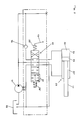
- Fig. 1 zeigt unter Weglassung unwesentlicher Teile einen Ladekran von der Seite,
- Fig. 2 schematisch die erfindungsgemäße Steuerung bzw. Betätigung der einzelnen Teile des Verlängerungsarmes.
- Der dargestellte Ladekran weist einen auf einem Sockel 8 um eine vertikale Achse drehbaren Ständer 3 auf, der entgegen der Richtung des Auslegers 5 nach hinten geneigt ist. Die Schwenkachse 4, um welche der Ausleger 5 auf und ab bewegt werden kann, ist gegenüber dem Zentrum des Sockels 8 etwas auf jene Seite verschoben, auf welcher der Kipparm 7 am Ständer 3 vorbeigeführt werden soll. Der Kipparm 7, welcher den nur schematisch dargestellten, mehrteiligen Verlängerungsarm 11 trägt, ist um eine zentrale Achse 9 um den Ausleger 5 nach unten verschwenkbar, die Bewegung des Kipparms 7 erfolgt durch eine Hydraulikeinheit 6, die einerseits am Kipparm, anderseits an zwei Paaren von Schwenkhebeln befestigt ist. Die Schwenkhebel 1 und 2 sind ihrerseits entweder mit dem Ausleger 5 oder mit dem Kipparm 7 verbunden.
- Jeder Teil des in Fig. 1 dargestellten Verlängerungsarmes 11 ist über eine Kolbenstange 12 ausschiebbar, wobei nur die Kolbenstange für den äußersten Teil des teleskopartigen Verlängerungsarmes 11 zeichnerisch dargestellt ist.
- In Hinblick auf die großen Ausschublängen ist es notwendig, die Kolbenstange 12 relativ dick zu machen. Dieser scheinbare Nachteil läßt sich in einen Vorteil verwandeln, wenn die Dicke der Kolbenstange 12 so gewählt wird, daß zumindest bei unbelastetem Kran, vorteilhafterweise aber auch noch bei Anbringung geringer Lasten, der Querschnitt der Kolbenstange 12 ausreicht, um bei gleichzeitiger Beaufschlagung der Zylinderräume 22 und 22′ eine für den Ausschub hinreichende Hydraulikkraft zu garantieren. Unter dieser Voraussetzung ist es sinnvoll, das Schiebeventil 19 gegenüber dem Stand der Technik um den Schieberabschnitt 21 zu ergänzen.
- Abgesehen vom Abschnitt 21 entspricht die in Fig. 2 dargestellte Anordnung dem Stand der Technik. Die an einem Kolben 13 befestigte Kolbenstange 12 ist also in einem Zylinder 14 geführt, wobei die Zylinderräume 22 und 22′ beidseits des Kolben 13 mit Öl gefüllt sind. Dieses Öl wird der Hydraulikeinheit 23 über ein Schiebeventil 19 durch eine Pumpe 17 zugeführt. Das Schiebeventil 19 ist durch einen Handhebel 15 betätigbar und wird durch Federn 20,20′ in die in Fig. 2 dargestellte neutrale Stellung zurückgeführt, wenn der Handhebel 15 freigelassen wird. In der dargestellten neutralen Stellung fließt die Hydraulikflüssigkeit von der Pumpe 17 zurück in den Tank 18. Verschiebt man den Handhebel 15 nach links, ist die gesamte linke Fläche des Kolbens 13 beaufschlagt, das Rücköl fließt aus dem Zylinderraum 22′ ungehindert in den Tank 18 ab. Ein Rückschlagventil 16 verhindert das ungewollte Einschieben der Kolbenstange 12 gegen die Wirkung der Pumpe 17 bei Überlast.
- Verschiebt man den Handhebel 15 nach rechts, so wird die Kolbenstange 12 relativ rasch nach links verschoben, da nur die Differenz der Flächen von Kolben 13 und Kolbenstange 12 wirksam wird.
- Gegenüber dem Stand der Technik unterscheidet sich die dargestellte Einrichtung nun insofern, als ein Schieberabschnitt 21 es möglich macht, gleichzeitig die Zylinderräume 22 und 22′ mit dem Druck des von der Pumpe 17 geförderten Öls zu beaufschlagen. Dies bedeutet, daß Rücköl aus dem Zylinderraum 22′ in den Zylinderraum 22 gelangt oder, mit anderen Worten, daß statt der Fläche des Kolbens 13 nur mehr die Fläche der Kolbenstange 12 wirksam ist. Dies ist dann sinnvoll, wenn die so erzeugte geringere Kraft auf den Kolben 12 ausreicht, andererseits aber die erzielte höhere Geschwindigkeit gewünscht wird.
- Bei der Bedienung der dargestellten Einrichtung wird der Handhebel 15 zuerst um eine Stufe nach links verschoben, woraufhin sich die Kolbenstange 12 langsam in Bewegung setzt. Eine weitere Verschiebung in die extrem linke Stellung, in welcher der Schieberabschnitt 21 wirksam ist, führt zu einem raschen Ausschub, soferne die auf die Koblenstange 12 ausgeübte Kraft überhaupt für den Ausschub ausreicht. Sollte die Bedienungsperson sehen, daß dies nicht der Fall ist, läßt sie den Handhebel 12 einfach unter Federwirkung in die Stellung zurückgleiten, welche der normalen Ausschubgeschwindigkeit entspricht.
Claims (1)
- Auf einem Lastfahrzeug anbringbarer Ladekran, der einen gegenüber dem Ständer des Kranes um eine horizontale Achse schwenkbaren Ausleger mit einem an dessen äußerem Ende ebenfalls um eine horizontale Achse schwenkbaren Kipparm sowie einen koaxial zum Kipparm sich erstreckenden, gegebenenfalls mehrteiligen Verlängerungsarm aufweist, wobei der Verlängerungsarm bzw. dessen Teile durch Hydraulikeinheiten ausschiebbar sind, indem je ein in Richtung auf eine neutrale Stellung federbelastetes Schiebeventil mittels eines Handhebels in eine der neutralen Stellung benachbarte Stellung gebracht wird, in der lediglich die der Kolbenstange abgewandte Seite des Kolbens der Hydraulikeinheit druckbeaufschlagt ist, dadurch gekennzeichnet, daß durch weitere Auslenkung des Handhebels (15) das Schiebeventil (19) in eine Stellung bringbar ist, in welcher in an sich bekannter Weise beide Seiten des Kolbens (13) druckbeaufschlagt sind, das Rücköl also vom kolbenstangenseitigen Zylinderraum (22′) in den anderen Zylinderraum (22) rückgeführt wird.
Applications Claiming Priority (2)
| Application Number | Priority Date | Filing Date | Title |
|---|---|---|---|
| AT309488A ATA309488A (de) | 1988-12-20 | 1988-12-20 | Ladekran |
| AT3094/88 | 1988-12-20 |
Publications (1)
| Publication Number | Publication Date |
|---|---|
| EP0374775A1 true EP0374775A1 (de) | 1990-06-27 |
Family
ID=3545222
Family Applications (1)
| Application Number | Title | Priority Date | Filing Date |
|---|---|---|---|
| EP89123311A Withdrawn EP0374775A1 (de) | 1988-12-20 | 1989-12-16 | Ladekran |
Country Status (2)
| Country | Link |
|---|---|
| EP (1) | EP0374775A1 (de) |
| AT (1) | ATA309488A (de) |
Cited By (2)
| Publication number | Priority date | Publication date | Assignee | Title |
|---|---|---|---|---|
| WO1993010034A1 (de) * | 1991-11-11 | 1993-05-27 | Palfinger Aktiengesellschaft | Mehrstufiger teleskopausleger |
| US5501346A (en) * | 1991-11-11 | 1996-03-26 | Palfinger Aktiengesellschaft | Multistage telescope boom |
Citations (3)
| Publication number | Priority date | Publication date | Assignee | Title |
|---|---|---|---|---|
| FR1405554A (fr) * | 1964-07-16 | 1965-07-09 | Hydraulic Unit Specialities Co | Distributeur de commande de vitesse et de direction pour cylindre élévateur à double effet |
| US3686862A (en) * | 1971-04-14 | 1972-08-29 | Bucyrus Erie Co | Hydraulic system for single engine truck crane or the like |
| EP0066567A2 (de) * | 1981-06-01 | 1982-12-08 | Firma PALFINGER | Auf einem Lastfahrzeug anbringbarer Ladekran |
-
1988
- 1988-12-20 AT AT309488A patent/ATA309488A/de not_active Application Discontinuation
-
1989
- 1989-12-16 EP EP89123311A patent/EP0374775A1/de not_active Withdrawn
Patent Citations (3)
| Publication number | Priority date | Publication date | Assignee | Title |
|---|---|---|---|---|
| FR1405554A (fr) * | 1964-07-16 | 1965-07-09 | Hydraulic Unit Specialities Co | Distributeur de commande de vitesse et de direction pour cylindre élévateur à double effet |
| US3686862A (en) * | 1971-04-14 | 1972-08-29 | Bucyrus Erie Co | Hydraulic system for single engine truck crane or the like |
| EP0066567A2 (de) * | 1981-06-01 | 1982-12-08 | Firma PALFINGER | Auf einem Lastfahrzeug anbringbarer Ladekran |
Cited By (2)
| Publication number | Priority date | Publication date | Assignee | Title |
|---|---|---|---|---|
| WO1993010034A1 (de) * | 1991-11-11 | 1993-05-27 | Palfinger Aktiengesellschaft | Mehrstufiger teleskopausleger |
| US5501346A (en) * | 1991-11-11 | 1996-03-26 | Palfinger Aktiengesellschaft | Multistage telescope boom |
Also Published As
| Publication number | Publication date |
|---|---|
| ATA309488A (de) | 1990-09-15 |
Similar Documents
| Publication | Publication Date | Title |
|---|---|---|
| DE60110472T2 (de) | Verfahren zum Betreiben eines hydraulischen Systems für einen Radlader | |
| DE2257175A1 (de) | Gabelstapler | |
| EP1752587B1 (de) | Hydraulische Anordnung | |
| DE2937814C2 (de) | ||
| DE102017126386A1 (de) | Baumaschine mit Ausleger | |
| DE602004001836T2 (de) | Transportabler Gabelhubwagen | |
| DE3043590A1 (de) | Hydraulische kippvorrichtung fuer das fahrerhaus eines lastkraftwagens | |
| DE6907627U (de) | Materialbewegungsvorrichtung mit verstellbarer steuereinrichtung | |
| DE3739525C2 (de) | ||
| DE2066194C2 (de) | ||
| DE2224383C3 (de) | Vorrichtung zum Kippen und Verriegeln des Fahrerhauses von Lastkraftwagen | |
| DE19730499A1 (de) | Hydraulische Kippvorrichtung | |
| DE2240552A1 (de) | Vorrichtung zum handhaben von lasten | |
| DE3439292A1 (de) | Hydraulisch betaetigte hubvorrichtung, insbesondere hebebuehne fuer kraftfahrzeuge | |
| DE4038730C2 (de) | ||
| DE3004289A1 (de) | Vorrichtung zur parallelfuehrung des loeffels eines hydraulikbaggers | |
| DE1527289C2 (de) | Steuerung für Schmiedemanipulatoren | |
| DE60002192T2 (de) | Kraftfahrzeug mit kippbarer kabine | |
| DE2834480C2 (de) | Steuereinrichtung eines Schaufelladers od.dgl. | |
| DE4229842C1 (de) | Hydraulische Kippvorrichtung zum Kippen des Fahrerhauses eines Lastkraftwagens | |
| DE1191645B (de) | Steuerung fuer hydraulische Antriebe mit einem Steuerventil oder -schieber mit einer Arretierung | |
| DE2853109A1 (de) | Vorsatzgeraet fuer einen hublader mit zueinander verschiebbaren teilen | |
| DE4231637C2 (de) | Bremseinrichtung für einen über einen Antrieb bewegbaren Teil | |
| DE19819270B4 (de) | Seitenstapler | |
| DE2757054C2 (de) | Hydraulische Fahrerhaus-Kippvorrichtung |
Legal Events
| Date | Code | Title | Description |
|---|---|---|---|
| PUAI | Public reference made under article 153(3) epc to a published international application that has entered the european phase |
Free format text: ORIGINAL CODE: 0009012 |
|
| AK | Designated contracting states |
Kind code of ref document: A1 Designated state(s): AT DE ES FR IT SE |
|
| STAA | Information on the status of an ep patent application or granted ep patent |
Free format text: STATUS: THE APPLICATION IS DEEMED TO BE WITHDRAWN |
|
| 18D | Application deemed to be withdrawn |
Effective date: 19901228 |