EP0374786A2 - Système pour conduire l'air amené - Google Patents
Système pour conduire l'air amené Download PDFInfo
- Publication number
- EP0374786A2 EP0374786A2 EP89123361A EP89123361A EP0374786A2 EP 0374786 A2 EP0374786 A2 EP 0374786A2 EP 89123361 A EP89123361 A EP 89123361A EP 89123361 A EP89123361 A EP 89123361A EP 0374786 A2 EP0374786 A2 EP 0374786A2
- Authority
- EP
- European Patent Office
- Prior art keywords
- nozzle
- supply air
- air
- supply system
- air supply
- Prior art date
- Legal status (The legal status is an assumption and is not a legal conclusion. Google has not performed a legal analysis and makes no representation as to the accuracy of the status listed.)
- Withdrawn
Links
- 238000009423 ventilation Methods 0.000 claims abstract description 16
- 238000007789 sealing Methods 0.000 claims description 4
- 238000007599 discharging Methods 0.000 abstract description 2
- 238000010586 diagram Methods 0.000 description 3
- 238000003912 environmental pollution Methods 0.000 description 2
- 230000002411 adverse Effects 0.000 description 1
- 239000000809 air pollutant Substances 0.000 description 1
- 231100001243 air pollutant Toxicity 0.000 description 1
- 238000007664 blowing Methods 0.000 description 1
- 230000000694 effects Effects 0.000 description 1
- 238000005265 energy consumption Methods 0.000 description 1
- 230000007613 environmental effect Effects 0.000 description 1
- 239000003344 environmental pollutant Substances 0.000 description 1
- 231100000719 pollutant Toxicity 0.000 description 1
Images
Classifications
-
- F—MECHANICAL ENGINEERING; LIGHTING; HEATING; WEAPONS; BLASTING
- F24—HEATING; RANGES; VENTILATING
- F24F—AIR-CONDITIONING; AIR-HUMIDIFICATION; VENTILATION; USE OF AIR CURRENTS FOR SCREENING
- F24F13/00—Details common to, or for air-conditioning, air-humidification, ventilation or use of air currents for screening
- F24F13/02—Ducting arrangements
- F24F13/06—Outlets for directing or distributing air into rooms or spaces, e.g. ceiling air diffuser
- F24F13/065—Outlets for directing or distributing air into rooms or spaces, e.g. ceiling air diffuser formed as cylindrical or spherical bodies which are rotatable
-
- F—MECHANICAL ENGINEERING; LIGHTING; HEATING; WEAPONS; BLASTING
- F24—HEATING; RANGES; VENTILATING
- F24F—AIR-CONDITIONING; AIR-HUMIDIFICATION; VENTILATION; USE OF AIR CURRENTS FOR SCREENING
- F24F13/00—Details common to, or for air-conditioning, air-humidification, ventilation or use of air currents for screening
- F24F13/26—Arrangements for air-circulation by means of induction, e.g. by fluid coupling or thermal effect
-
- B—PERFORMING OPERATIONS; TRANSPORTING
- B64—AIRCRAFT; AVIATION; COSMONAUTICS
- B64D—EQUIPMENT FOR FITTING IN OR TO AIRCRAFT; FLIGHT SUITS; PARACHUTES; ARRANGEMENT OR MOUNTING OF POWER PLANTS OR PROPULSION TRANSMISSIONS IN AIRCRAFT
- B64D13/00—Arrangements or adaptations of air-treatment apparatus for aircraft crew or passengers, or freight space
- B64D2013/003—Cabin ventilation nozzles
Definitions
- the invention relates to an air supply system, in particular for introducing air into industrial rooms.
- the inventor has set himself the goal of developing a system of the type mentioned above, by means of which the supply air supply is optimized while substantially saving energy.
- the solution to this problem is that an approximately perpendicular branch pipe is connected to at least one main duct for discharging the supply air at predetermined points in the room.
- the main duct thus leads the supply air in the ceiling area. From there, the branch pipe branches off to the predetermined location, this predetermined location generally being in the vicinity of machines. In this way, supply air is only discharged where it is needed. The rest of the hall remains free of supply air, although the supply air is not required at these other places. However, this means that overall a much smaller amount of supply air has to be supplied, so that the energy required for this is also minimized.
- the branch tube For structural reasons, it should generally prove better to arrange the branch tube approximately perpendicular to the main channel. Corresponding angular ranges should, however, also be encompassed by the concept of the invention, since, for example, an angle of the stub tube running at 10 ° to the vertical certainly does not have an adverse effect on work in the factory hall. However, the flange of the branch pipe on the main channel must then be reinforced on one side, which in turn entails an increased amount of work.
- a cross ventilation pipe which is equipped with at least one nozzle, should preferably be connected to the branch pipe.
- a nozzle register is made available, which can be individually adjusted by the operator. This is especially true when the nozzles are designed to be movable. For example, it is possible to couple four or more nozzles with one another, so that a selective introduction of air is possible. Throwing distances and top speeds can be read on the basis of diagrams at different temperature differences and the nozzles can also be set accordingly.
- each nozzle is rigidly connected to the cross ventilation pipe. It has proven advantageous here to insert the nozzle into an annular collar, against which it is supported with the interposition of a sealing strip. For the sake of simplicity, the ring collar is then connected via a screw to a clamping profile which has a constriction through which a stop is formed, which in turn is seated on a flange on the nozzle.
- a clamping profile which has a constriction through which a stop is formed, which in turn is seated on a flange on the nozzle.
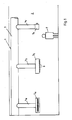
- a ventilation duct 1 for one factory hall 2, which is only indicated, has one or more main ducts 3.
- This main channel 3 runs at the top of the ceiling of the factory hall 2, so that work in the factory hall 2 itself is not hindered.
- a branch pipe 4a, 4b or 4c branches off from the main channel 3 approximately vertically downward.
- the corresponding supply air thus passes through the main duct 3 through the branch pipe 4 and the cross ventilation pipe 5 from the nozzles 6, the throwing distances of these nozzles being able to be determined very precisely using corresponding diagrams.
- These nozzles can either be arranged evenly distributed on the cross ventilation pipe 5 or can be used selectively so that they separate a heat source, for example a corresponding machine (not shown), from a machine operator 7 by an air curtain.
- the height of the arrangement of the cross ventilation pipes 5 also depends on the height of the factory building 2 and also on the arrangement of corresponding heat sources.
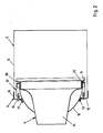
- a nozzle 6 is rigidly inserted into the cross-ventilation pipe 5 as a single nozzle.
- the connection to the side walls 8 of the cross ventilation pipe 5 is provided by an S-shaped annular collar 9, one leg 10 of which is connected to the side wall 8, while the other leg 11 is supported against a nozzle cap 13 with the interposition of a sealing strip 12.
- a central strip 15 of the ring collar 9 is penetrated by a screw 16, which on the other hand engages in a clamping profile 17 for the nozzle 6.
- This clamping profile 17 has a constriction 18 through which an annular stop 19 for a circumferential flange 20 is formed on the nozzle cap 13.
- the supply air can be evenly fed into the room in an air jet.
- punctual introduction of air for example four nozzles blowing onto one point. Thanks to a flexible connection, these four individual nozzles can be adjusted according to the wishes of the operating personnel.
- nozzles can also be connected to one another in this way.
- the throwing distances and the top speeds of the nozzles can be read off using diagrams at different temperature differences, so that an optimal supply of air is guaranteed.
- the main advantage of this entire supply air management system is that the supply air is brought directly to the workplace where it is needed.
- the exhaust air is then, as not shown in more detail, taken from the top of the factory hall, with the heated air filled with pollutants being extracted here, for example.
Landscapes
- Engineering & Computer Science (AREA)
- Chemical & Material Sciences (AREA)
- Combustion & Propulsion (AREA)
- Mechanical Engineering (AREA)
- General Engineering & Computer Science (AREA)
- Duct Arrangements (AREA)
- Ventilation (AREA)
- Pipeline Systems (AREA)
- Respiratory Apparatuses And Protective Means (AREA)
Applications Claiming Priority (2)
| Application Number | Priority Date | Filing Date | Title |
|---|---|---|---|
| DE19883842718 DE3842718A1 (de) | 1988-12-19 | 1988-12-19 | Zuluftfuehrungssystem |
| DE3842718 | 1988-12-19 |
Publications (2)
| Publication Number | Publication Date |
|---|---|
| EP0374786A2 true EP0374786A2 (fr) | 1990-06-27 |
| EP0374786A3 EP0374786A3 (fr) | 1991-01-09 |
Family
ID=6369533
Family Applications (1)
| Application Number | Title | Priority Date | Filing Date |
|---|---|---|---|
| EP19890123361 Withdrawn EP0374786A3 (fr) | 1988-12-19 | 1989-12-18 | Système pour conduire l'air amené |
Country Status (2)
| Country | Link |
|---|---|
| EP (1) | EP0374786A3 (fr) |
| DE (1) | DE3842718A1 (fr) |
Cited By (2)
| Publication number | Priority date | Publication date | Assignee | Title |
|---|---|---|---|---|
| DE9420413U1 (de) * | 1994-12-21 | 1995-02-16 | Gebrüder Trox, GmbH, 47506 Neukirchen-Vluyn | Düseneinrichtung zur Belüftung von Räumen mit einem Einbaurahmen und einer schwenkbaren Düse, die eine äußere Führungswand und eine innere Düsenwand aufweist |
| RU2816134C1 (ru) * | 2023-07-19 | 2024-03-26 | федеральное государственное бюджетное образовательное учреждение высшего образования "Санкт-Петербургский горный университет императрицы Екатерины II" | Устройство для принудительного проветривания рабочих мест |
Families Citing this family (1)
| Publication number | Priority date | Publication date | Assignee | Title |
|---|---|---|---|---|
| SE527241C2 (sv) * | 2000-02-17 | 2006-01-24 | Fresh Ab | Flödesstabiliserat ventilationssystem |
Family Cites Families (7)
| Publication number | Priority date | Publication date | Assignee | Title |
|---|---|---|---|---|
| DE536837C (de) * | 1931-10-28 | Marinus Rappard | In kugelfoermigem Traeger angeordnetes Mundstueck fuer Lueftungseinrichtungen | |
| DE1763566U (de) * | 1958-01-08 | 1958-03-20 | Schilde Maschb Ag | Mundstueck fuer belueftungseinrichtungen u. dgl. |
| US3122201A (en) * | 1960-05-05 | 1964-02-25 | Carrier Corp | Air conditioning system |
| AT293690B (de) * | 1969-07-15 | 1971-10-25 | Zumtobel Kg | Einrichtung bei Klimaanlagen, insbesondere bei Klimaleuchten |
| DE2601557A1 (de) * | 1976-01-16 | 1977-07-21 | Wilhelmi Holzwerk | Haengedecke |
| DE2735643A1 (de) * | 1977-08-08 | 1979-02-22 | Adam Jakob | Luftauslass fuer die klimatisierung von aufenthaltsraeumen |
| DE3124876C2 (de) * | 1981-06-25 | 1985-09-19 | Schako Metallwarenfabrik Ferdinand Schad Kg, 7201 Kolbingen | Weitwurfdüse |
-
1988
- 1988-12-19 DE DE19883842718 patent/DE3842718A1/de not_active Withdrawn
-
1989
- 1989-12-18 EP EP19890123361 patent/EP0374786A3/fr not_active Withdrawn
Cited By (2)
| Publication number | Priority date | Publication date | Assignee | Title |
|---|---|---|---|---|
| DE9420413U1 (de) * | 1994-12-21 | 1995-02-16 | Gebrüder Trox, GmbH, 47506 Neukirchen-Vluyn | Düseneinrichtung zur Belüftung von Räumen mit einem Einbaurahmen und einer schwenkbaren Düse, die eine äußere Führungswand und eine innere Düsenwand aufweist |
| RU2816134C1 (ru) * | 2023-07-19 | 2024-03-26 | федеральное государственное бюджетное образовательное учреждение высшего образования "Санкт-Петербургский горный университет императрицы Екатерины II" | Устройство для принудительного проветривания рабочих мест |
Also Published As
| Publication number | Publication date |
|---|---|
| EP0374786A3 (fr) | 1991-01-09 |
| DE3842718A1 (de) | 1990-06-28 |
Similar Documents
| Publication | Publication Date | Title |
|---|---|---|
| WO1997016365A1 (fr) | Aiguillage pour systeme de transport pneumatique | |
| EP1086313B1 (fr) | Dispositif de maintenance pour systemes a air comprime | |
| AT392927B (de) | Absaugsystem fuer den bereich der holzverarbeitung | |
| EP0374786A2 (fr) | Système pour conduire l'air amené | |
| DE10124315C1 (de) | Vakuumspanneinrichtung für Werkstücke für stationär bearbeitende Maschinen | |
| EP2647770A1 (fr) | Excavatrice à succion pneumatique pour l'aspiration de matériaux | |
| DE1186602B (de) | Klimatisierungsanlage fuer Textilmaschinen | |
| DE2851046A1 (de) | Luftauslassvorrichtung fuer raumklimatisierungs- und belueftungsanlagen | |
| AT390436B (de) | Verfahren und vorrichtung zur kompostierung organischer abfallstoffe | |
| EP3901336A1 (fr) | Métier à filer doté d'une pluralité de postes de travail les uns à côté des autres, ainsi que procédé de fonctionnement d'un métier à filer doté d'une pluralité de postes de travail les uns à côté des autres | |
| EP2037198A2 (fr) | Installation de séchage d'une multitude de moules en plâtre de préférence en plusieurs parties | |
| EP0175056A1 (fr) | Dispositif de transport pneumatique de flocons de fibres | |
| DE8815736U1 (de) | Zuluftführungsvorrichtung | |
| EP0253216A2 (fr) | Dispositif de fabrication de feuilles en matière plastique | |
| EP0739723B1 (fr) | Dispositif de flottage pour guider des feuilles dans une machine d'impression ou analogue | |
| DE3004073A1 (de) | Raumlueftungseinrichtung | |
| DE1934237C3 (de) | Einrichtung zum zwangläufigen Längsbelüften eines Straßentunnels großer Länge | |
| DE102021121177A1 (de) | Vorrichtung zum Behandeln von Behältnissen mit abgestütztem Reinraum | |
| EP1504876B1 (fr) | Appareil de dégazage pour extrudeuse | |
| DE2418358A1 (de) | Trocknungsanlage | |
| DD284274A5 (de) | Verfahren zur belueftung von hydroponikgetriebenen pflanzenkulturen, insbesondere von chicoree | |
| DE7006342U (de) | Vorrichtung zum beschleunigen und verteilen von klimaluft in raeumen mit klimadecken. | |
| DE1685977A1 (de) | Verfahren und Vorrichtung zum Klimatisieren von Textilmaschinen | |
| DE102004040113A1 (de) | Spinnmaschine mit Absaugsystem | |
| DE1918644C3 (de) | Pneumatische Entleerungsvorrichtung für ein Silo |
Legal Events
| Date | Code | Title | Description |
|---|---|---|---|
| PUAI | Public reference made under article 153(3) epc to a published international application that has entered the european phase |
Free format text: ORIGINAL CODE: 0009012 |
|
| AK | Designated contracting states |
Kind code of ref document: A2 Designated state(s): AT BE CH DE ES FR GB GR IT LI LU NL SE |
|
| PUAL | Search report despatched |
Free format text: ORIGINAL CODE: 0009013 |
|
| RHK1 | Main classification (correction) |
Ipc: F24F 13/00 |
|
| AK | Designated contracting states |
Kind code of ref document: A3 Designated state(s): AT BE CH DE ES FR GB GR IT LI LU NL SE |
|
| 17P | Request for examination filed |
Effective date: 19910610 |
|
| 17Q | First examination report despatched |
Effective date: 19920117 |
|
| STAA | Information on the status of an ep patent application or granted ep patent |
Free format text: STATUS: THE APPLICATION IS DEEMED TO BE WITHDRAWN |
|
| 18D | Application deemed to be withdrawn |
Effective date: 19930615 |