EP0374873A2 - Transfert de masse entre un liquide et un gaz à l'aide de membranes microporeuses sous forme de fibres - Google Patents
Transfert de masse entre un liquide et un gaz à l'aide de membranes microporeuses sous forme de fibres Download PDFInfo
- Publication number
- EP0374873A2 EP0374873A2 EP89123534A EP89123534A EP0374873A2 EP 0374873 A2 EP0374873 A2 EP 0374873A2 EP 89123534 A EP89123534 A EP 89123534A EP 89123534 A EP89123534 A EP 89123534A EP 0374873 A2 EP0374873 A2 EP 0374873A2
- Authority
- EP
- European Patent Office
- Prior art keywords
- gas
- liquid
- conduit
- membrane
- fibers
- Prior art date
- Legal status (The legal status is an assumption and is not a legal conclusion. Google has not performed a legal analysis and makes no representation as to the accuracy of the status listed.)
- Withdrawn
Links
Images


Classifications
-
- B—PERFORMING OPERATIONS; TRANSPORTING
- B01—PHYSICAL OR CHEMICAL PROCESSES OR APPARATUS IN GENERAL
- B01D—SEPARATION
- B01D53/00—Separation of gases or vapours; Recovering vapours of volatile solvents from gases; Chemical or biological purification of waste gases, e.g. engine exhaust gases, smoke, fumes, flue gases, aerosols
- B01D53/22—Separation of gases or vapours; Recovering vapours of volatile solvents from gases; Chemical or biological purification of waste gases, e.g. engine exhaust gases, smoke, fumes, flue gases, aerosols by diffusion
-
- B—PERFORMING OPERATIONS; TRANSPORTING
- B01—PHYSICAL OR CHEMICAL PROCESSES OR APPARATUS IN GENERAL
- B01D—SEPARATION
- B01D19/00—Degasification of liquids
- B01D19/0031—Degasification of liquids by filtration
-
- B—PERFORMING OPERATIONS; TRANSPORTING
- B01—PHYSICAL OR CHEMICAL PROCESSES OR APPARATUS IN GENERAL
- B01D—SEPARATION
- B01D61/00—Processes of separation using semi-permeable membranes, e.g. dialysis, osmosis or ultrafiltration; Apparatus, accessories or auxiliary operations specially adapted therefor
-
- B—PERFORMING OPERATIONS; TRANSPORTING
- B01—PHYSICAL OR CHEMICAL PROCESSES OR APPARATUS IN GENERAL
- B01D—SEPARATION
- B01D61/00—Processes of separation using semi-permeable membranes, e.g. dialysis, osmosis or ultrafiltration; Apparatus, accessories or auxiliary operations specially adapted therefor
- B01D61/36—Pervaporation; Membrane distillation; Liquid permeation
- B01D61/364—Membrane distillation
-
- B—PERFORMING OPERATIONS; TRANSPORTING
- B01—PHYSICAL OR CHEMICAL PROCESSES OR APPARATUS IN GENERAL
- B01D—SEPARATION
- B01D63/00—Apparatus in general for separation processes using semi-permeable membranes
- B01D63/02—Hollow fibre modules
- B01D63/026—Wafer type modules or flat-surface type modules
-
- B—PERFORMING OPERATIONS; TRANSPORTING
- B01—PHYSICAL OR CHEMICAL PROCESSES OR APPARATUS IN GENERAL
- B01D—SEPARATION
- B01D63/00—Apparatus in general for separation processes using semi-permeable membranes
- B01D63/02—Hollow fibre modules
- B01D63/04—Hollow fibre modules comprising multiple hollow fibre assemblies
- B01D63/043—Hollow fibre modules comprising multiple hollow fibre assemblies with separate tube sheets
-
- B—PERFORMING OPERATIONS; TRANSPORTING
- B01—PHYSICAL OR CHEMICAL PROCESSES OR APPARATUS IN GENERAL
- B01D—SEPARATION
- B01D2313/00—Details relating to membrane modules or apparatus
- B01D2313/40—Adsorbents within the flow path
-
- B—PERFORMING OPERATIONS; TRANSPORTING
- B01—PHYSICAL OR CHEMICAL PROCESSES OR APPARATUS IN GENERAL
- B01D—SEPARATION
- B01D2319/00—Membrane assemblies within one housing
- B01D2319/04—Elements in parallel
Definitions
- This invention relates to efficient mass transfer of a volatile component between a gas stream and a liquid stream flowing through microporous membrane fibers.
- An object of the present invention is to provide an apparatus and method for the efficient removal of one or more gases from a gaseous mixture stream or the efficient transfer of a vaporous component of a liquid mixture/solution stream to an absorbent stream by the use of microporous membrane fibers.
- the invention comprises an apparatus and method for transferring one or more gases from a gaseous mixture or volatile components from a liquid mixture/solution into an absorbing gas or liquid, wherein said gaseous mixture or said liquid mixture/solution is flowing in a conduit.
- the invention requires contacting the gaseous or liquid mixture with an array of closely spaced gas porous polymeric microporous hollow membrane fibers mounted inside the conduit such that said flowing gas or liquid mixture flows through said array, contacting the exterior surfaces of said fibers.
- Each hollow membrane fiber of the array passes through the walls of said conduit and has first and second ends connected, beyond the walls of said conduit, to an inlet manifold and an outlet manifold, respectively.
- the method of the invention next requires flowing an absorbent into said inlet manifold, through the bores of said fibers, and out said outlet manifold.
- the gas or volatile component to be removed from the mixture permeates and transfers from the exterior of said hollow fibers into said bore where it is absorbed by said absorbent.
- the microporous hollow membrane fiber array comprises one or more layers of a woven cloth having weft and warp fibers.
- the method of the invention is directed to transfering a gas from a mixture into an absorbent liquid flowing through the bores of said fibers.
- the apparatus and method of the invention offers an advantage over prior art gas-liquid mass transfer apparatus and methods in that the gas flow rate is independent of the liquid flow rate.
- the invention achieves mass transfer coefficients equal to and in excess of those of the prior art at gas and liquid flow rates reduced by at least an order of magnitude from the gas and liquid flow rates necessary for conventional apparatus such as a packed tower.
- This invention permits significant reduction in the size of the mass transfer equipment that forms the gas-liquid mass transfer interface and a corresponding reduction of the size of ancillary equipment, such as gas handling and liquid handling equipment necessary to attain reasonable mass transfer rates.
- This invention is based on the discovery that mass transfer which results between a liquid and a gas, said liquid flowing through the bores of a plurality of microporous membrane fibers arranged in a cloth assembly and positioned in a gas stream substantially perpendicular to the flow of the gas stream, more than compensates for the pressure loss in the gas stream.
- the invention will be initially described as an absorption device for the transfer of components from a gas or vapor stream into a liquid stream.
- the practitioner will readily understand, however, that conversely, the device and processes described are readily applicable to stripping or desorption as well, i.e., transfer of a volatile component from a liquid to a stream of gas or vapor.
- Suitable gases which may be transferred to or from the liquid phase in a microporous hollow membrane fiber include volatile hydrocarbons, volatile halogenated hydrocarbons, volatile oxygenated hydrocarbons, ammonia, volatile amines, hydrogen sulfide, sulfur dioxide, halogen gas, and carbon oxides.
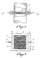
- microporous hollow membrane fibers arranged in a generally planar array (1) are interposed in a gas conduit (2) so as to intersect the flow of a gas stream in the conduit containing the component to be transferred from the gas stream to the liquid stream, or vice versa.
- the generally planar array of microporous hollow membrane fibers permits the flow of gas through the porous array. While individual membrane fibers or bundles of fibers may be randomly or regularly oriented in the generally planar array, it is advantageous to weave the fibers into cloth.
- the cloth form of membrane fibers array aids in maintaining a uniform spacing between individual membrane fibers to prevent channeling of gas flow through the fibers which would reduce mass transfer efficiency.
- the weft threads of the microporous cloth aid by maintaining dimensional stability of the membrane fibers during fabrication.
- the orientation of the array of membrane fibers will be perpendicular to the direction of flow of the gas within the conduit.
- the array of membrane fibers may be positioned in any non-perpendicular orientation to gas flow in the conduit.
- Figures 2 and 3 illustrate an apparatus installed directly in a conduit containing a gas mixture stream having a component to be transferred.
- a liquid flows in the bores of the microporous hollow fibers.
- the liquid chosen is one in which the gas component to be transferred is miscible or the gas and liquid phase react to form a nearly irreversible liquid reaction product.
- the selection criteria for choosing a suitable liquid to effect mass transfer are generally the same criteria as would be considered if the mass transfer apparatus were a conventional packed tower.
- the practitioner will often select a suitable mass transfer liquid from water, an aqueous acid, an aqueous base, a liquid hydrocarbon, a liquid oxygenated hydrocarbon, a liquid sulfur containing hydrocarbon, or a liquid halogenated hydrocarbon.
- the cloth of microporous hollow membrane fibers advantageously is larger than the cross-section of the conduit containing the gas flow.
- the limitng dimension of microporous hollow membrane cloth will be in the direction of the fabric weft (i.e. width of the cloth).
- the apparatus may be assembled by weaving strips of narrower hollow microporous membrane cloth, as a tape, in lattice fashion into a layered microporous membrane cloth of the necessary size and shape to form a generally planar porous intercept in the gas conduit.
- the cloth of microporous hollow membrane fibers must be sealed to prevent escape of gas from the conduit as well as the entrance of bore liquid into the gas conduit. Such sealing can be provided by installing the microporous membrane cloth in a suitably modified segment of gas flow conduit.
- a modified segment of gas flow conduit may consist of a single section of conduit having located therein an array of microporous membrane fibers.
- a modified segment of gas flow conduit may consist of an array of microporous membrane fibers interposed between two sections of gas flow conduit.
- the modified segment of gas flow conduit may then be assembled with other sections of gas flow tube by conventional methods in a manner so as to avoid material interference with gas flow.
- a generally planer array of microporous hollow membrane fibers is illustrated as installed in a conduit or pipe (2).
- the bores of the cloth or other array of microporous hollow membrane fibers connect with a liquid inlet (5) by means of an inlet manifold (6).
- the bores of the cloth or other array of microporous hollow membrane fiber connect with a liquid outlet (8) by means of an outlet manifold (9).
- the microporous hollow membrane fibers may be sealed by conventional methods such as potting the substantially planar membrane apparatus around the perimeter of the gas conduit in a chemically setting polymer resin such as epoxy.
- the open ends of the hollow microporous membrane fibers forming the warp end of the membrane cloth are advantageously similarly potted into a traditional tube sheet.
- the liquid inlet tube sheet (4) and liquid outlet tubesheet (3) are sealingly engaged with their respective manifolds to permit the bore liquid to flow from the liquid inlet (5) through the bores of the fibers forming the array (1).
- the bore fluid is collected by the outlet manifold (9) and discharged by outlet (8).
- the gas conduit and membrane cloth are arranged to minimize channeling of the gas flow through the cloth of microporous membrane and to cause the gas to come into intimate, impinging contact with the exterior surfaces of the hollow microporous membrane fibers of the membrane cloth.
- a substantially uniform resistance to gas flow through the microporous membrane fiber, and consequently substantially uniform gas flow through the planar array of microporous membrane fibers is advantageously achieved by potting a plurality of membrane cloth layers having their respective weft and warp directions parallel. Or, such uniform distribution may be achieved by potting a pluralty of microporous membrane cloth sections having their respective weft and warp directions perpendicular.
- such uniform gas flow distribution be achieved by a plurality of layers of microporous membrane cloth having their weft and warp orientations varied by one or more angular degrees with respect to the warp and weft directions of one or more adjacent cloth layers.
- Other apparent methods of achieving substantially uniform gas flow across the entire cross-section of microporous membrane fibers are contemplated herein.
- Microporous hollow polymer fibers suitable for this invention and for use as yarn for the weaving of microporous membrane cloth useful in this invention has an outside diameter of 1 cm to 10 ⁇ m, advantageously 0.1 mm to 1 mm, most advantageously from 0.25 mm. to 0.75 mm.
- Said hollow fiber as yarn useful in this invention has a permeability to nitrogen gas of 1.0 x 10 ⁇ 1 cc/sec-cm2-cmHg, to 1.0 x 10 ⁇ 4 cc/sec-cm2-cmHg, advantageously 5.0 x 10 ⁇ 2 cc/sec-cm2-cmHg to 1.0 x 10 ⁇ 3 cc/sec-cm2-cmHg.
- Said microporous fiber useful in this invention has a wall thickness of 5 ⁇ m to 50 ⁇ m, advantageously from 10 ⁇ m to 40 ⁇ m.
- Polymeric materials suitable for the preparation of microporous membrane fibers of this invention are advantageously selected after consideration of the physical properties of the polymeric material, the operating environment anticipated for the membrane apparatus and the resistance to attack of the polymeric material by the liquid phase and gas phase chemicals.
- Microporous membrane cloth made from hollow fibers of polyolefin is commercially available.
- Polyolefin microporous fibers and microporous hollow fibers of other hydrophobic polymeric materials are particularly suited to gas-liquid systems wherein the liquid phase is polar or water based. In such systems, the hydrophobic character of the polymeric material tends to keep the liquid phase within the hollow fiber.
- a microporous fiber formed from a hydrophilic polymeric material such as polysulfone is advantageous.
- a gas recovery or purification apparatus similar to that shown in Figure 1 is made using as a porous barrier layers of microporous hollow membrane cloth made of microporous polyethylene fibers.
- the microporous membrane cloth used may be purchased from CD Medical Inc., 14600 NW 60 Ave., P.O. Box 9308, Miami Lakes, FL 33014-9308.
- the cloth has a dimension of 9 cm to 9.5 cm in the warp direction, and a thickness of from 0.3 mm to 0.4 mm.
- the fibers have an outside diameter of 300 ⁇ m to 350 ⁇ m.
- Ten layers of the cloth are assembled having the weft direction of alternate layers oriented at right angles to adjacent layers.
- the ends of the weft of microporous membrane fibers are potted in epoxy resin to form tube sheets for the microporous membrane fibers.
- the tube sheets are sealingly engaged to a liquid conduit to form a manifold to the open ends of the microporous membrane fibers.
- the apparatus is assembled in a gas conduit segment made of polycarbonate having an inside diameter of 7.6 cm extending 30 cm in each direction from the membrane apparatus.
- An apparatus is assembled as in Example 1 except that, instead of 10 layers of membrane cloth, the apparatus is assembled from 20 layers of the same membrane cloth used in Example 1. Another apparatus including 50 layers of membrane cloth is also assembled.
- the mass transfer rates between the gas phase and the liquid phase of the microporous membrane apparatus described herein may be expected to be influenced by a variety of factors including the thermodynamics of the mass transfer components of the liquid and gas phases which influence the mass transfer in the apparatus and method of the instant invention as those factors influence the mass transfer in conventional apparatus and methods.
- the overall mass transfer between the liquid and gas phase will depend as well on the porosity of the microporous membranes, the number of layers of microporous membrane fibers, or advantageously layers of membrane cloth, planarly positioned in the gas conduit transverse to the direction of gas flow.
- the number of layers of membrane fibers will in turn be limited by the energy loss tolerable in the gas stream flow as measured by gas stream pressure drop across the gas porous membrane barrier.
- the number of layers of membrane cloth may be one hundred or more, conveniently less than sixty layers, and more advantageously less than forty layers, but generally at least five layers.
- a driving force in the operation of the apparatus and method of the instant invention is the flow of gas across the surface of the microporous membrane fibers.
- Gas phase flow within the gas conduit is achieved according to conventional methods and apparatus such as compressors, pumps and blowers.
- a mechanical pressure differential develops across the membrane mass transfer apparatus.
- the upper limit of the pressure difference is limited by the physical strength of the microporous membrane fibers installed.
- the fibers may be supported in the gas conduit by wire screen or other mechanical support means in order to operate the apparatus at larger pressure differences across the membranes than would be attainable if the polymeric microporous hollow fiber membranes were unsupported.
- Mass transfer between gas phase and liquid phase is effective at such pressure difference across the membrane apparatus as will cause gas to flow through the porous planar array of membrane fibers intimately contacting individual microporous membrane fibers.
- said pressure difference is from nearly zero to 10 meters of water, advantageously from 0.003 cm of water to 100 cm of water, more advantageously from 0.02 cm of water to 10 cm of water.
- the gas phase pressure loss is related to the liquid flow rate.
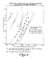
- a typical graphic representation of gas phase pressure loss for ceramic tower packing material is shown in Figure 4.
- the solid lines plotted in Figure 4 are gas phase pressure losses for 1 in (2.54 cm) nominal size commercially available ceramic saddles.
- the data is adapted from the manufacturers data.
- the active surface area of gas-liquid mass transfer in conventional unit operations, such as in a packed tower varies with the rate of fluid flow: the rate of gas phase mass transfer increases with increased gas phase flow rate; the liquid phase mass transfer rate increases with the liquid flow rate. McCabe and Smith, Unit Operations of Chemical Engineering , McGraw-Hill Book Co., 1967, p. 667.
- the gas phase flow rate is independent of the liquid phase flow rate because the cross-section area of the microporous hollow membrane fibers does not measurably vary with the flow of liquid in the bore of the hollow membrane fiber.
- Figure 4 also graphically shows a gas phase pressure loss across a membrane apparatus of 10, 20, and 50 membrane cloth layers. The gas phase pressure loss across the membrane apparatus in the gas conduit is shown on Figure 4 to approach a linear relationship to the number of membrane cloth layers in the generally planar array of fibers.
- a further mass transfer driving force is the flow rate of liquid in the bores of the microporous fibers of the planar array. If the liquid in the microporous hollow membrane fiber remains stagnant in the membrane fiber indefinitely an equilibrium concentration of the gas phase component intended to be transferred to the liquid phase will eventually result. As for conventional gas-liquid mass transfer systems, the liquid phase must be renewed at the gas-liquid interface in order to provide a driving force between the equilibrium concentration of the gas phase component and the same component in the liquid phase.
- the liquid flow rate for conventional gas-liquid mass transfer systems is often expressed as a ratio of the mass of liquid to the mass of gas entering the mass transfer apparatus.
- Effective ratios of inlet liquid mass to inlet gas mass for the apparatus of the instant invention may range from 100 kg (l) to 1 kg (g) to 10 kg (g) to 1 kg (l) ; more effective will be ratios of liquid to gas ranging from 60 kg (l) to 1 kg (g) to 1 kg (l) to 1 kg (g) ; most effective will be ratios ranging from 30 kg (l) to 1 kg (g) , to 3 kg (l) to 1 kg (g) .
- Figure 4 Graphically represented in Figure 4 is the data reported in Table 1. Also graphically represented is gas phase pressure loss across the membrane layers of the apparatus prepared according to Examples 1 and 2, including gas phase pressure loss of an apparatus having 50 layers of microporous membrane fiber cloth. Figure 4 suggests that the gas side pressure loss nearly linearly relates to the number of membrane fiber layers (membrane cloth layers) positioned normal to the gas flow.
- microporous polymer membrane cloth as a generally planar gas-permeable or porous barrier in the gas flow conduit at a near normal orientation to the direction of the longitudinal axis of the conduit, which direction is also the direction of gas flow within the conduit, will result in a pressure loss when measured across the membrane cloth, surprisingly the inefficiencies caused by the pressure drop are more than offset by the increased mass transfer which results from the use of the hollow fiber microporous membrane apparatus and the method here described.
- Mass transfer from the gas phase to the liquid phase using the apparatus of this invention in the method described can result in mass transfer rates which in a packed tower are attainable only at gas phase flow rates several orders of magnitude greater than the gas phase flow rates required by the apparatus used in the method of this invention.
- Liquid flow rates are also substantially reduced by use of the apparatus and method disclosed herein.
- the ratio of liquid phase flow rates to gas phase flow rates for the membrane apparatus of this invention and the ratio of liquid phase flow rates to gas phase flow rates for conventional packed towers are closely parallel. But, the total mass flow of the liquid phase and gas phase necessary for the membrane apparatus to achieve mass transfer coefficients comparable to mass transfer coefficients of conventional methods are reduced by orders of magnitude from the liquid phase and gas phase flow rates of conventional packed towers.
- a mass transfer rate of 3 lb moles/hr-ft3-atm (39 g moles/hr-m3-atm) can be achieved at a gas flow rate of 500 lb/hr-ft2 (4.9 kg/hr-m2).
- This gas flow rate corresponds to a liquid flow rate of 5,000 lb/hr-ft2 (49 kg/hr-m2).
- the comparison data show, as noted above, that in order for the packed tower of commercial ceramic saddles to attain a mass transfer coefficient of 3 lb. moles/hr-ft3-atm (49 g- molds/hr. m3 atm), it is necessary for the packed tower to have a gas flow rate of 500 lb/ft2-hr (2440 kg/hr-m2), and a liquid flow rate of 5,000 lb/ft2-hr (24400 kg/hr-m2).
- the membrane device of Example 4 achieves a similar mass transfer coefficient with a gas flow rate of only 2 lb/ft2-hr (9.8 kg/hr-m2) and a liquid flow rate of aqueous 1N NaOH of only 16 lb/ft2-hr (78 kg/hr-m2).
- the apparatus described herein in the form of a small economical and efficient unit can effectively reduce the levels of atmospheric emissions of an undesired gas or vapor more simply and effectively than can be done with a packed tower.
- the apparatus is particularly suited as a vent stack stripper for such vapors as hydrocarbon solvents, for example; but not by way of limitation, C1-C6 halogen substituted hydrocarbon, a C1-C6 monovalent or divalent oxygen substituted hydrocarbon, C1-C8 amine substituted hydrocarbon, volatile inorganic acids such as hydroflouric acid or hydrochloric acid, volatile organic acids such as acetic acid, and methane sulfonic acid. and water-soluble gases such as ammonia, hydrogen sulfide, sulfur dioxide, and halogen gases.
- a further advantage of the apparatus and method of the instant invention is the installation versatility afforded by a membrane apparatus as described herein.
- a packed tower must be installed in a vertical orientation in order to create the countercurrent flow between the denser liquid phase drawn downward by the force of gravity and the upward flow of the less dense gas phase.
- the membrane apparatus described herein achieves a gas-liquid interface independent of gravity-influenced countercurrent flow.
- the membrane stripper as described herein may be installed in any orientation convenient to the application.
- a further advantage of the apparatus and method of the instant invention is the potential to produce liquid stream product of sufficient concentration to be useful as a result of the high mass transfer coefficient made possible with the instant invention.
- the approximate minimum size useful packed tower has a diameter of 10 cm or approximately 4 inches.
- a mass transfer coefficient of 3 lb moles/hr-ft3-atm (49 g moles/hr-m3-atm) from an air stream containing 1 percent CO2 scrubbed by aqueous 1N NaOH with a liquid-to-gas ratio of 10 requires a minimum gas flow of approximately 42 lb/hr (19 kg/hr) of 1 percent CO2.
- a membrane apparatus as disclosed herein for the same gas stream and liquid absorber can achieve the same coefficient of mass transfer starting at a gas flow rate of only 0.165 lb/hr (75 g/hr) and a liquid flow rate of 1.3 lbs/hr (590 g/hr).
- the membrane apparatus can also efficiently treat low volume atmospheric emission sources not possible by conventional methods.
Landscapes
- Chemical & Material Sciences (AREA)
- Chemical Kinetics & Catalysis (AREA)
- Engineering & Computer Science (AREA)
- Water Supply & Treatment (AREA)
- Analytical Chemistry (AREA)
- General Chemical & Material Sciences (AREA)
- Oil, Petroleum & Natural Gas (AREA)
- Separation Using Semi-Permeable Membranes (AREA)
- Gas Separation By Absorption (AREA)
Applications Claiming Priority (2)
| Application Number | Priority Date | Filing Date | Title |
|---|---|---|---|
| US28724988A | 1988-12-20 | 1988-12-20 | |
| US287249 | 1988-12-20 |
Publications (2)
| Publication Number | Publication Date |
|---|---|
| EP0374873A2 true EP0374873A2 (fr) | 1990-06-27 |
| EP0374873A3 EP0374873A3 (fr) | 1991-01-23 |
Family
ID=23102077
Family Applications (1)
| Application Number | Title | Priority Date | Filing Date |
|---|---|---|---|
| EP19890123534 Withdrawn EP0374873A3 (fr) | 1988-12-20 | 1989-12-20 | Transfert de masse entre un liquide et un gaz à l'aide de membranes microporeuses sous forme de fibres |
Country Status (4)
| Country | Link |
|---|---|
| EP (1) | EP0374873A3 (fr) |
| JP (1) | JPH02211227A (fr) |
| BR (1) | BR8906613A (fr) |
| CA (1) | CA2005959A1 (fr) |
Cited By (8)
| Publication number | Priority date | Publication date | Assignee | Title |
|---|---|---|---|---|
| EP0464945A1 (fr) * | 1990-07-03 | 1992-01-08 | Shell Internationale Researchmaatschappij B.V. | Module à membranes pour des séparations de liquides à écoulement à contre-courant |
| WO1996017672A1 (fr) * | 1994-12-09 | 1996-06-13 | Nederlandse Organisatie Voor Toegepast-Natuurwetenschappelijk Onderzoek Tno | Procede et installation de traitement d'un fluide |
| NL9500202A (nl) * | 1995-02-03 | 1996-09-02 | Tno | Werkwijze en inrichting voor het behandelen van een medium. |
| EP0882493A2 (fr) * | 1994-06-22 | 1998-12-09 | Fls Miljo A/S | Procédé de transfert de masse |
| US10688435B2 (en) | 2017-02-27 | 2020-06-23 | Honeywell International Inc. | Dual stripper with water sweep gas |
| US10702826B2 (en) | 2017-12-12 | 2020-07-07 | University Of Kentucky Research Foundtion | Method and apparatus for increasing mass transfer in aqueous gas adsorption processes |
| WO2021064441A1 (fr) * | 2019-10-03 | 2021-04-08 | Sorin Group Italia S.R.L. | Systèmes et procédés pour éliminer des micro-emboles gazeux présents dans le sang |
| US11123685B2 (en) | 2017-02-27 | 2021-09-21 | Honeywell International Inc. | Hollow fiber membrane contactor scrubber/stripper for cabin carbon dioxide and humidity control |
Families Citing this family (15)
| Publication number | Priority date | Publication date | Assignee | Title |
|---|---|---|---|---|
| WO1997002883A1 (fr) * | 1995-07-07 | 1997-01-30 | Nederlandse Organisatie Voor Toegepast- Natuurwetenschappelijk Onderzoek Tno | Procede pour absorption de constituants gazeux oxydables ou reductibles a travers une membrane |
| US6209855B1 (en) | 1999-05-10 | 2001-04-03 | Canzone Limited | Gas/liquid mixing apparatus and method |
| AU2004210726A1 (en) | 2003-02-13 | 2004-08-26 | Zenon Technology Partnership | Supported biofilm apparatus and process |
| US7175763B2 (en) | 2003-02-13 | 2007-02-13 | Zenon Technology Partnership | Membrane supported biofilm process for autotrophic reduction |
| US7294259B2 (en) | 2003-02-13 | 2007-11-13 | Zenon Technology Partnership | Membrane module for gas transfer |
| WO2005016498A1 (fr) * | 2003-08-18 | 2005-02-24 | Zenon Environmental Inc. | Module membrane pour transfert gazeux et traitement par film biologique supporte par une membrane |
| CN100361907C (zh) | 2003-02-13 | 2008-01-16 | 泽农技术合伙公司 | 受支撑的生物薄膜设备和反应器及处理液体方法 |
| US7303676B2 (en) | 2003-02-13 | 2007-12-04 | Zenon Technology Partnership | Supported biofilm apparatus and process |
| US7300571B2 (en) | 2003-02-13 | 2007-11-27 | Zenon Technology Partnership | Supported biofilm apparatus |
| HUE052058T2 (hu) | 2007-04-20 | 2021-04-28 | Zenon Tech Partnership | Membrán által tartott biofilm berendezés és eljárás |
| EP4733273A2 (fr) | 2013-02-22 | 2026-04-29 | BL Technologies, Inc. | Ensemble membrane pour supporter un biofilm |
| CA3207201A1 (fr) | 2014-03-20 | 2015-09-24 | Bl Technologies, Inc. | Traitement d'eaux usees par un traitement primaire et reacteur mbr ou mabr-ifas |
| US10785996B2 (en) | 2015-08-25 | 2020-09-29 | Cornelius, Inc. | Apparatuses, systems, and methods for inline injection of gases into liquids |
| US10477883B2 (en) | 2015-08-25 | 2019-11-19 | Cornelius, Inc. | Gas injection assemblies for batch beverages having spargers |
| US11040314B2 (en) | 2019-01-08 | 2021-06-22 | Marmon Foodservice Technologies, Inc. | Apparatuses, systems, and methods for injecting gasses into beverages |
Family Cites Families (6)
| Publication number | Priority date | Publication date | Assignee | Title |
|---|---|---|---|---|
| US3342729A (en) * | 1964-12-09 | 1967-09-19 | Dow Chemical Co | Permeability separatory cell and apparatus and method of using the same |
| FR2222134A1 (en) * | 1973-03-19 | 1974-10-18 | Rhone Poulenc Sa | Appts for permeation through hollow fibres - allows simple construction and efficient separation and mixing processes |
| FR2236537B1 (fr) * | 1973-07-11 | 1977-12-23 | Rhone Poulenc Ind | |
| DE2617985C3 (de) * | 1976-04-24 | 1979-02-22 | Draegerwerk Ag, 2400 Luebeck | Atemluftanfeuchter für Beatmungsvorrichtungen |
| CA1094462A (fr) * | 1977-05-06 | 1981-01-27 | Pierre J. Morin | Dispositif d'echange par diffusion a travers une membrane |
| JPS551816A (en) * | 1978-06-15 | 1980-01-09 | Mitsubishi Rayon Co Ltd | Vapor-liquid contactor |
-
1989
- 1989-12-19 CA CA002005959A patent/CA2005959A1/fr not_active Abandoned
- 1989-12-20 EP EP19890123534 patent/EP0374873A3/fr not_active Withdrawn
- 1989-12-20 JP JP1328583A patent/JPH02211227A/ja active Pending
- 1989-12-20 BR BR898906613A patent/BR8906613A/pt unknown
Cited By (12)
| Publication number | Priority date | Publication date | Assignee | Title |
|---|---|---|---|---|
| EP0464945A1 (fr) * | 1990-07-03 | 1992-01-08 | Shell Internationale Researchmaatschappij B.V. | Module à membranes pour des séparations de liquides à écoulement à contre-courant |
| US5143613A (en) * | 1990-07-03 | 1992-09-01 | Shell Oil Company | Counter-current membrane module for liquid separation |
| EP0882493A2 (fr) * | 1994-06-22 | 1998-12-09 | Fls Miljo A/S | Procédé de transfert de masse |
| US6309550B1 (en) | 1994-06-22 | 2001-10-30 | Fls Miljo A/S | Mass transfer method and apparatus |
| WO1996017672A1 (fr) * | 1994-12-09 | 1996-06-13 | Nederlandse Organisatie Voor Toegepast-Natuurwetenschappelijk Onderzoek Tno | Procede et installation de traitement d'un fluide |
| NL9500202A (nl) * | 1995-02-03 | 1996-09-02 | Tno | Werkwijze en inrichting voor het behandelen van een medium. |
| US10688435B2 (en) | 2017-02-27 | 2020-06-23 | Honeywell International Inc. | Dual stripper with water sweep gas |
| US11123685B2 (en) | 2017-02-27 | 2021-09-21 | Honeywell International Inc. | Hollow fiber membrane contactor scrubber/stripper for cabin carbon dioxide and humidity control |
| US11707709B2 (en) | 2017-02-27 | 2023-07-25 | Honeywell International Inc. | Hollow fiber membrane contactor scrubber/stripper for cabin carbon dioxide and humidity control |
| US10702826B2 (en) | 2017-12-12 | 2020-07-07 | University Of Kentucky Research Foundtion | Method and apparatus for increasing mass transfer in aqueous gas adsorption processes |
| WO2021064441A1 (fr) * | 2019-10-03 | 2021-04-08 | Sorin Group Italia S.R.L. | Systèmes et procédés pour éliminer des micro-emboles gazeux présents dans le sang |
| US12280323B2 (en) | 2019-10-03 | 2025-04-22 | Sorin Group Italia S.R.L. | Systems and methods for removing gaseous micro emboli from blood |
Also Published As
| Publication number | Publication date |
|---|---|
| EP0374873A3 (fr) | 1991-01-23 |
| JPH02211227A (ja) | 1990-08-22 |
| BR8906613A (pt) | 1990-08-21 |
| CA2005959A1 (fr) | 1990-06-20 |
Similar Documents
| Publication | Publication Date | Title |
|---|---|---|
| EP0374873A2 (fr) | Transfert de masse entre un liquide et un gaz à l'aide de membranes microporeuses sous forme de fibres | |
| CA1266367A (fr) | Methode et dispositif de separation de gaz par permeation selective | |
| US5282964A (en) | Boreside feed hollow fiber membrane device | |
| US6228145B1 (en) | Method for removing carbon dioxide from gases | |
| US6165253A (en) | Apparatus for removal of volatile organic compounds from gaseous mixtures | |
| US9541302B2 (en) | Flat panel contactors and methods | |
| US6478852B1 (en) | Method of producing nitrogen enriched air | |
| US6789288B2 (en) | Natural gas dehydration process and apparatus | |
| JP2902339B2 (ja) | ガス脱水法 | |
| EP1627041B1 (fr) | Procede et appareil de separation de gaz | |
| US6755894B2 (en) | Hollow fiber membrane gas separation cartridge and gas purification assembly | |
| US4147754A (en) | System for selective removal of hydrogen sulfide from a mixture of gases | |
| US5328610A (en) | Self-supported low pressure drop hollow fiber membrane panel and contactor module | |
| ES2388918T3 (es) | Procedimientos que utilizan membranas de permeabilidad selectiva de sólidos en múltiples grupos para la recuperación simultánea de productos específicos a partir de una mezcla de fluidos | |
| AU7322191A (en) | Spiral-wound membrane separation device with feed and permeate/sweep fluid flow control | |
| US7686868B2 (en) | Membrane module for separation of fluids | |
| US9072987B2 (en) | Method and apparatus for desorption using a microporous membrane operated in wetted mode | |
| AU2021390535A1 (en) | Tubular membrane heat exchanger | |
| CA1128316A (fr) | Methode de separation des gaz de synthese en melange | |
| US12017180B2 (en) | Improving sulfur recovery operations with processes based on novel CO2 over SO2 selective membranes and its combinations with SO2 over CO2 selective membranes | |
| JPH0259016A (ja) | ガス分離膜モジュール | |
| Guha et al. | A larger-scale study of gas separation by hollow-fiber-contained liquid membrane permeator | |
| JPS60193519A (ja) | 油分除去装置 | |
| He et al. | Removal of aqueous phase trichloroethylene using membrane air stripping contactors | |
| WO1991018665A1 (fr) | Dispositif de separation a membrane a spirale, a deux tuyaux, a double flux, et a contre-courant |
Legal Events
| Date | Code | Title | Description |
|---|---|---|---|
| PUAI | Public reference made under article 153(3) epc to a published international application that has entered the european phase |
Free format text: ORIGINAL CODE: 0009012 |
|
| AK | Designated contracting states |
Kind code of ref document: A2 Designated state(s): BE DE FR GB IT LU NL |
|
| PUAL | Search report despatched |
Free format text: ORIGINAL CODE: 0009013 |
|
| AK | Designated contracting states |
Kind code of ref document: A3 Designated state(s): BE DE FR GB IT LU NL |
|
| 17P | Request for examination filed |
Effective date: 19910710 |
|
| 17Q | First examination report despatched |
Effective date: 19920323 |
|
| STAA | Information on the status of an ep patent application or granted ep patent |
Free format text: STATUS: THE APPLICATION IS DEEMED TO BE WITHDRAWN |
|
| 18D | Application deemed to be withdrawn |
Effective date: 19940824 |