EP0374883A2 - System für Querverkehr zwischen lokalen Netzen - Google Patents
System für Querverkehr zwischen lokalen Netzen Download PDFInfo
- Publication number
- EP0374883A2 EP0374883A2 EP89123554A EP89123554A EP0374883A2 EP 0374883 A2 EP0374883 A2 EP 0374883A2 EP 89123554 A EP89123554 A EP 89123554A EP 89123554 A EP89123554 A EP 89123554A EP 0374883 A2 EP0374883 A2 EP 0374883A2
- Authority
- EP
- European Patent Office
- Prior art keywords
- frame
- local area
- area network
- received
- internetwork
- Prior art date
- Legal status (The legal status is an assumption and is not a legal conclusion. Google has not performed a legal analysis and makes no representation as to the accuracy of the status listed.)
- Granted
Links
Images


Classifications
-
- H—ELECTRICITY
- H04—ELECTRIC COMMUNICATION TECHNIQUE
- H04L—TRANSMISSION OF DIGITAL INFORMATION, e.g. TELEGRAPHIC COMMUNICATION
- H04L12/00—Data switching networks
-
- H—ELECTRICITY
- H04—ELECTRIC COMMUNICATION TECHNIQUE
- H04L—TRANSMISSION OF DIGITAL INFORMATION, e.g. TELEGRAPHIC COMMUNICATION
- H04L12/00—Data switching networks
- H04L12/28—Data switching networks characterised by path configuration, e.g. LAN [Local Area Networks] or WAN [Wide Area Networks]
- H04L12/46—Interconnection of networks
- H04L12/4637—Interconnected ring systems
-
- H—ELECTRICITY
- H04—ELECTRIC COMMUNICATION TECHNIQUE
- H04L—TRANSMISSION OF DIGITAL INFORMATION, e.g. TELEGRAPHIC COMMUNICATION
- H04L12/00—Data switching networks
- H04L12/28—Data switching networks characterised by path configuration, e.g. LAN [Local Area Networks] or WAN [Wide Area Networks]
-
- H—ELECTRICITY
- H04—ELECTRIC COMMUNICATION TECHNIQUE
- H04L—TRANSMISSION OF DIGITAL INFORMATION, e.g. TELEGRAPHIC COMMUNICATION
- H04L12/00—Data switching networks
- H04L12/28—Data switching networks characterised by path configuration, e.g. LAN [Local Area Networks] or WAN [Wide Area Networks]
- H04L12/46—Interconnection of networks
- H04L12/4604—LAN interconnection over a backbone network, e.g. Internet, Frame Relay
- H04L12/462—LAN interconnection over a bridge based backbone
- H04L12/4625—Single bridge functionality, e.g. connection of two networks over a single bridge
Definitions
- This invention relates to communication between different networks and, more particularly, to communication between a plurality of local area networks (LANs) including ring-type LANs and, even more particularly, to communication between different networks without using an internetwork transfer frame for internetwork communication after circulation in a ring-type LAN.
- LANs local area networks
- LAN local area networks
- IEEE Institute of Electrical and Electronic Engineers
- ANSI American National Standards Institute
- ISO International Organization for Standardization
- a popular ring-type LAN is the token ring or Fiber Distributed Data Interface (FDDI) system controlled by a media access control (MAC) system.
- FDDI Fiber Distributed Data Interface
- MAC media access control
- the right of transmission is shifted between nodes by circulating a control frame call token throughout the network.
- a node desiring to send at least one frame waits to seize the token. After seizing the token, the node first transmits the frames to be sent and then, to transfer the right of transmission to the next node on the ring, retransmits the token after transmission of the frames. The node later receives the frames after they have circulated around the ring and does not retransmit them, thus eliminating the frames from the ring.
- a flexible and low cost system for communication between different LANs is needed.
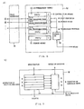
- FIG. 1 shows an example of a conventional network structure for mutual connection between two LANs.
- the network connects LAN I and LAN II through bridge 1, the interface for communication between different networks.
- Nodes 2, 3 and 4 belong to LAN I and nodes 5, 6 and 7 belong to LAN II in the example of FIG. 1.
- Bridge 1 is also a node belonging to both LANs I and II and functions as a media access control (MAC) bridge for controlling transmission and reception of internetwork transfer frames, for internetwork mutual communication between, for example, the nodes 3 and 5. Internetwork communication between other nodes is thus possible.
- MAC media access control
- FIG. 2 shows an example of another conventional network structure in which a plurality of networks are mutually connected.
- Ring-type LAN III is a token ring provided with bridge stations 8 and 9 as well as nodes 10 and 11.
- LAN III is connected with LANs IV and V through bridge stations 8 and 9.
- LAN IV is provided with terminals 12, 13, 14 and LAN V is provided with terminals 15, 16, 17.
- Mutual internetwork communication of internetwork frames over LANs III, IV and V is carried out through bridge stations 8 and 9.
- FIG. 3 shows a conventional frame format applied to the Fiber Distributed Data Interface (FDDI) type of LAN.
- each frame is composed of a plurality of fields: a phase synchronization (preamble) PA, a start delimiter SD, a frame control FC, a distant apparatus (destination node) address DA, a self apparatus (start node) address SA, an information part INFO, a frame check sequence FCS, an end delimiter ED, and a frame status FS.
- the phase synchronization DA is used for phase synchronization upon reception;
- the start delimiter SD is used for indicating the frame start position; and the end delimiter ED is used for indicating the frame end position.
- a node of the known Fiber Distributed Data Interface (FDDI) type of LAN erases and will not retransmit a received frame when the self apparatus (start node) address SA of the received frame matches the address of the node because the node assumes the frame is a frame previously transmitted by itself.
- FDDI Fiber Distributed Data Interface
- bridge 1 when bridge 1 is structured to operate like the ordinary nodes, as described above, problems occur in the event the self apparatus (start node) address SA in the received frame matches the node number or address of bridge 1.
- a frame used in a method of formatting a received frame is illustrated in Prior Art FIG. 4.
- the distant apparatus node address DA in the transfer frame is the address of node 5 and the self apparatus node address SA is the address of node 3.
- the frame is formatted as illustrated in FIG. 4, information INFO1 is defined as part of information INFO2 which also includes the original destination DA and start SA addresses; self apparatus node address SA is assigned to the address of bridge 1; and distant apparatus node address DA is assigned to the address of node 5.
- This new transfer frame is transmitted to the LAN II by bridge 1.
- the receiving node 5 analyzes the content of information part INFO2 in the received frame to determine that the self apparatus node address SA is the address of node 3.
- Each node in a LAN using this type of internetwork communication is required to provide not only the self apparatus address SA, but also the ability to analyze the self apparatus from the content of INFO2 to deal with two kinds of frame format illustrated in FIGS. 3 and 4. As a result, a more complicated system is required.
- An object of the present invention is to provide an internetwork connecting unit which does not require modification of frame format for internetwork transfer between connected LANs.
- Another object of the present invention is to provide an internetwork connecting unit unaffected by network structure modification.
- a system for communication between different networks by controlling communication between local area networks including a ring-type local area network which operates by transmitting a dummy frame followed by an internetwork transfer frame to the ring-type local area network.
- the internetwork transfer frame contains data defining a node of the ring-type local area network as a distant apparatus (receiver) and a node of another local area network as a self apparatus (sender).
- the dummy frame is detected on the ring-type local area network, after transmission of the dummy frame around the ring, and the internetwork transfer frame received following the dummy frame from the ring-type local area network deleted.
- An internetwork transfer frame defines a node of the ring-type local area network as the distant apparatus address and a node of another local area network as a self apparatus address.
- the internetwork transfer frame is transmitted to the ring-type local area network.
- the distant apparatus address of the internetwork transfer frame is received, after circulation around the ring-type local area network, and compared to the stored distant apparatus address. When the received distant apparatus address matches the stored distant apparatus address, the internetwork transfer frame is deleted from the ring-type local area network.
- communication between networks is similarly achieved.
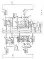
- FIG. 5 is a block diagram of an internetwork connecting unit according to a first embodiment of the present invention. An example will be described for receiving the internetwork transfer frame at node 5 of LAN II transmitted from node 3 of LAN I via bridge 1.
- the internetwork connection unit, bridge 1, for transmitting or receiving frames between LAN I and LAN II is described below with reference to FIG. 5.
- the frame transmitted from node 3 of LAN I is received by frame receiver 23 and a timing signal is generated in accordance with the phase synchronization read from phase synchronization PA of the frame (see FIG. 3).
- the received frame in frame receiver 23 is supplied to receiving controller 24, receiving buffer 25 and selector 29 and is stored in receiving buffer 25.
- Receiving controller 24 detects the start delimiter SD of the received frame through the timing control of frame receiver 23, identifies the distant apparatus address DA and self apparatus address SA in the received frame and then forwards these addresses to microprocessor (MPU) 20 through control bus 42. Under the control of microprocessor 20, the received frame in the receiving buffer 25 is transferred to the system memory 21 via data bus 41.
- MPU microprocessor
- System memory 21 stores control information, such as frame format information, format conversion information for LAN I and LAN II, and address information of nodes 2 through 7 of LAN I and LAN II. System memory 21 also stores transfer frames from receiving buffer 25.
- the MPU 20 refers to the node address information of system memory 21 to decide whether the distant apparatus address DA sent from the receiving controller 24 belongs to LAN I or LAN II. The decisions made based on self apparatus address SA will be described later.
- the received frame is sent directly to LAN I, as described below.
- Selector 29 is normally set to select the output of frame receiver 23, although it can be switched to pattern generator 27 or to transmitting buffer 28 under control of transmitting controller 26 in response to a signal from MPU 20 or frame receiver 23. Therefore, a frame received by the frame receiver 23 can be sent directly to LAN I by frame transmitter 30 after passing through selector 29. Namely, the frame transmitted from node 3 passes through bridge 1 and MPU 20 clears the received frame stored in the receiving buffer 25.
- the frame received from LAN I is forwarded in the internetwork transfer frame for LAN II, as described below.
- Microprocessor 20 must convert, upon transfer of the received frame to the LAN II from the LAN I, the frame format of the received frame stored in the system memory 21 to the frame format used in the LAN II. Therefore, MPU 20 reads out the received frame from system memory 21 and converts the received frame into the format used in LAN II by referring to the format information stored in the system memory 20. The received frame after conversion, is transferred to transmitting buffer 38 through the data bus 41.
- Microprocessor 20 then instructs receiving controller 34 to seize the token circulating in LAN II to acquire the right of transmission on LAN II. Accordingly, the received frame is copied in the bridge 1 as the distant apparatus in LAN I and is then transmitted on LAN I again to circulate on LAN I toward the self apparatus node 3.
- the frame receiver 33 connected to LAN II, operates in the same way as the frame receiver 23 described above, wherein the received frame is input to the receiving controller 34, the receiving buffer 35 and the selector 39.
- the receiving controller 34 informs the MPU 20 via the control bus 42 of the seizure of the token. Thereby, the right of transmission on LAN II by the bridge 1 can be obtained.
- the bridge 1 is the frame sender in LAN II. Therefore, when the transfer frame sent to LAN II from the transmitting buffer 38 circulates LAN II and is received again by the bridge 1, it must be deleted. That is, the transfer frame transmitted by the bridge 1 itself must be identified and, therefore, the bridge 1 provides a self apparatus address management table circuit 49.
- the MPU 20 accumulates and stores the self apparatus addresses SA of such transfer frames as the identifier (SA) in the self apparatus address management table circuit 49.
- the MPU 20 sends a command to the transmitting controller 36 to send the transfer frame including its corresponding identifier (transmitting frame) to LAN II.
- the transmitting controller 36 controls the selector 39 to select the output of the transmitting buffer 38.
- the transmitter 40 sends the transfer frame to LAN II.
- This transfer frame is transmitted to LAN II from the transmitter 40 of the bridge 1. Thereafter, with the command from MPU 20, the transmitting controller 36 controls a pattern generator 37 and the selector 39 to select the output of the pattern generator 37.
- the pattern generator 37 generates the token pattern.
- the token is transmitted to LAN II from the pattern generator 37 through the selector 39 and transmitter 40. Thereby, the right of transmission is released and the MPU 20 controls the transmitting controller 36 so that the selector 39 can select the output of the frame receiver 33 as usual.
- the transfer frame sent to LAN II from the bridge 1 is fetched by node 5, reaches again the bridge 1 by circulating LAN II and is received by the frame receiver 33.
- the address indicated by the self apparatus address SA of the transfer frame is transferred to MPU 20 through the control bus 42.
- Microprocessor 20 then refers to the self apparatus address management table circuit 49 to determine if the self apparatus address SA of this transferred frame is stored in the self apparatus address management table circuit 49.
- the received frame is not the transfer frame to LAN II from LAN I transmitted on LAN II from the bridge 1 as the self apparatus. Accordingly, since selector 39 is switched to select the output of the frame receiver 33, the MPU 20 does not switch the selector 39 and the received frame is directly transmitted to LAN II from the transmitter 40.
- MPU 20 identifies that the received frame is the transfer frame to be transferred between networks to the LAN II via the bridge 1, and thus erases (eliminates) this frame from circulation in the ring of LAN II.
- MPU 20 sends a control signal to the transmitting controller 36.
- the transmitting controller 36 controls the selector 39 to select an output of the pattern generator 37 to send an idle pattern to the transmitter 40. Therefore, the data illustrated in FIG. 3, when the self apparatus address SA of the frame to be sent to LAN II is detected by the bridge 1 is replaced with the idle pattern and, thereby, erasure (elimination) of the frame sent from the self apparatus is complete. Such erasure (elimination) of the frame is called stripping.
- FIG. 6 is a block diagram of the self apparatus address management table circuit 49, described in detail below.
- the register in the SA management table 50 of self apparatus management table circuit 49 shown in FIG. 5 arranges flip-flops in columns of n+1 bits for each row.
- Address memories 52 are memory registers of n bits each, while control flags 51 are one bit memory registers. Each address memory 52 stores the self apparatus address of the transfer frame.
- control flag 51 indicates whether address memory 52 has registered a self apparatus address in that row.
- the flag is set (0 ⁇ 1) wh,en the transfer frame is transmitted and reset (1 ⁇ 0) when the relevant transfer frame is received.
- a number of bits in each row of the control flag 51 are set based on control content.
- the number of rows k of addresses 52 and control flags 51 are determined by considering the time t required for a transmited frame to circulate through the LAN II, the average length l of the ring and the circulating speed v (bit rate) of the ring.
- the pointer indicates the row for reading and writing of address memory 52 and control flag memory 51.
- First-in-first-out (FIFO) reading and writing is preferably implemented by returning the pointer to the leading row when it reaches the ending row.
- a transmitting pointer 55 for frame transmission and a strip pointer 56 for frame stripping are used for this purpose. Transmitting pointer 55 points to the row to read the originating address of the net frame to be transmitted.
- Strip pointer 56 points to the row to read the originating address of the oldest unchecked transmitted frame.
- the self apparatus addresses of the m transfer frames are sequentially registered in address memory 52 as shown in FIG. 6 and a corresponding flag is set in the control flag memory 51 to indicate that the self apparatus addresses SA for the m transfer frame are stored in the SA management table 50.
- the transfer frame transmitted to LAN II from the frame transmitter 40 circulates LAN II and is received again from LAN II in the frame receiving part 33.
- the self apparatus address SA of the transfer frame (the address of the node in LAN I) is then extracted from the transfer frame by MPU 20 via the receiving controller 34.
- the self apparatus address SA extracted from the transfer frame is also input to a comparator 53 provided in the self apparatus address management table circuit 49.
- the comparator 53 retrieves all address memory rows for which the flags are set in the control flag memory 51 and reads the self apparatus addresses registered in the retrieved rows of address memory 52.
- the comparator 53 recognizes matches between the self apparatus address read from the address memory 52 and the self apparatus address extracted from the transfer frame. When it is verified that the self apparatus address SA extracted from the transfer frame received from LAN II does not match any self apparatus address in address memory 52, the received frame is directly transmitted to LAN II through the frame transmitter 40 and the receiving buffer 35 is cleared. When the self apparatus address SA extracted from the transfer frame received from LAN II matches any self apparatus address stored in the address memory 52, the row indicated in the address memory 52 by the strip pointer 56 up to and including the row of the matching address are cleared by the comparator 53 and the strip pointer 56 is set to the row following the row containing the matching SA address.
- the row indicated by the strip pointer 56 matches the row of the matching SA address detected by (or in) the comparator 53.
- the self apparatus address SA cannot be extracted from the received transfer frame and the strip pointer 56 cannot be updated. Therefore, when another transfer frame is received later without error, the row indicated by the comparator 53 is beyond the row indicated by the strip pointer 56 by the number of transfer frames which generated an error.
- the bit error of a received frame is detected by MPU 20 with the frame check sequencer (FCS) bit in the frame. The received frame generating an error is deleted from the LAN, namely it is stripped.
- the rows of SA management table 50 in which the self apparatus address SA of the transfer frame generating an error is stored, are not cleared, the self apparatus addresses of the transfer frames which are already deleted from the LAN remain and, in the worst case, the SA management table 50 overflows.
- the row indicated by the strip pointer 56 up to and including the row of address matching indicated by the comparator 53 are cleared by the comparator 53.
- Such rows in the control flag memories 51 are reset by the comparator 53.
- the comparator 53 detecting a match of self apparatus addresses, informs MPU 20 of the matching addresses.
- the selector 39 selects the pattern generator 37 instead of the frame receiver 33 and the received transfer frame is deleted from LAN II.
- the self apparatus address of the received frame and each registered address of SA management table 50 are sequentially compared in the comparator 53 as shown in FIG. 7. This comparison may be simultaneously performed in parallel.
- the comparison method is selected considering the circuit structure, the scale of the circuit and the time required for comparison processing.
- the frame when the self apparatus address of a received transfer frame matches the registered address, the frame is ordinarily deleted in both the address memory 52 and the control flag memory 51. Alternatively it is possible to erase (reset) the frame only by operation of the control flag memory 51. It is also possible that a timer area can be provided to the control flag memory 51 of the SA management table 50 and the self apparatus address management table circuit 49 so that an erasing process is carried out to the relevant rows during a timeup period after a constant period from address registration. In this case, it is preferable that the timeup period be set a little longer than the time required for the transmitting frame to circulate in LAN II.
- FIG. 8 A block diagram of the internetwork connecting unit in a second embodiment of the present invention is shown in FIG. 8.
- the embodiment of FIG. 8 shows a structure of the bridge 1 in the mutually connected network as shown in FIG. 5 and the elements like those in FIG. 5 are given similar reference numerals.
- the frame receiver 23 can directly send the received frame to the frame transmitter 30 via the selector 29 and can send the received frame to MPU 20 and system memory 21.
- the frame receiving controller 24 analyzes the received frames circulating in LAN I. Moreover, the frame receiving controller 24 provides the function of acquiring the tokens circulating in LAN I and the function of detecting dummy frames described later.
- the transmitting controller 26 provides the functions of monitoring reception of dummy frames and notifying the number of frames to be transmitted or received following the dummy frames to a transmitting frame number counter 61 and controls the timing for deleting the frames.
- the dummy frame is generated by a dummy frame generator 60.
- FIG. 9 is a frame format of the dummy frame.
- the dummy frame contains the distant apparatus (destination node) address DA and self apparatus (start node) address SA set to the address of node 1 and also an ID code in the area corresponding to the information part INFO set to indicate that this frame is a dummy frame.
- the dummy frame can be distinguished from a frame returning to the self node from the self node, used for testing.
- the transmitting frame number counter 61 counts up a transmitting and receiving frame number. It provides the function of, during transmission, counting up the number of data frames transmitted following the dummy frame and, during reception, counting down the number of data frames transmitted from the self apparatus, received following the dummy frame.
- the frame receiving controller 34, frame transmitting controller 36, dummy frame generator 70 and sending frame number counter 71 also provides the same functions as those of respective circuits described for the ring-type LAN II and therefore explanation of these circuits is omitted.
- the frame transmitting sequence in the bridge 1 and an example of the counter value are shown in FIG. 10.
- the time axis is plotted in the vertical direction with time passing in the downward direction.
- the oblique arrow marks indicate that the transmitting frame for the self apparatus circulates the ring and is received by the self apparatus. Accordingly, the left side nodes and right side nodes are both accommodated in the same node, bridge 1 and the count value is also the same.
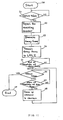
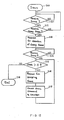
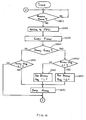
- the flow of transmission processing procedures for transmission of dummy frames in the bridge 1 is shown in FIG. 11 and the flow of reception processing procedures is shown in FIG. 12.
- An example is provided for frame transmission to node 5 of ring-type LAN II from node 3 of ring-type LAN I.
- the frame circulating through LAN I is received by the frame receiver 23 of the bridge 1 and is then sent to the frame receiving controller 24.
- MPU 20 checks whether the received frame is the internetwork transfer frame designated for transfer to the LAN II from the LAN I by making reference to the information stored in the system memory 21.
- the internetwork transfer frame is transferred to system memory 21 from the receiving buffer 25.
- MPU 20 converts the frame format of this transfer frame into that for LAN II, and transmits it to transmitting buffer 38.
- a process for transmitting this transfer frame to LAN II depends on the procedures of the flow chart of FIG. 11.
- the frame transmitting controller 36 monitors whether the frame receiver 33 has acquired the token providing the right of transmission in LAN II (step S1). When the frame receiver 33 has obtained the right of transmission (token), it resets a count value by issuing a reset request to the transmitting frame number counter 71 (step S2).
- the frame transmitting controller 36 starts the dummy frame generator 70, controls the selector 39 to select the output of the dummy frame generator 70 instead of the frame receiver 33, and then outputs from selector 39 a dummy frame having the format shown in FIG. 9. Namely, the frame transmitting controller 36 controls generation of a dummy frame setting the distant apparatus node addressed DA to the self node address (in this case, the address of node 1). Prior to transmission of an internetwork transfer frame stored in the transmitting buffer 38 and converted from the frame format of LAN 1 to that of LAN II by MPU 20, the generated dummy frame is transmitted to LAN II through the selector 39 and frame transmitter 40 (step S4).
- the frame transmitter 40 starts transmission of the dummy frame sent from the dummy frame generator 70 to the LAN II.
- the frame transmitting controller 36 monitors transmission of the dummy frame from the dummy frame generator 70.
- the frame transmission controller 36 controls the selector 39 to output the data frame, designating LAN II which is stored in the transmitting buffer memory 38, to the frame transmitter 40 which transmits the data frame to LAN II.
- This data frame is the internetwork transfer frame received by the frame receiver 23 of LAN I in which the distant apparatus node address DA corresponds to the node address (for example, No. 5) in LAN II and the self apparatus node address SA corresponds to the node address (for example, No. 3) in LAN I, as a result of only the format conversion by MPU 20.
- the frame transmitting controller 36 monitors transmission of a data frame from the transmitting buffer memory 38 and issues an instruction (step S7) to the transmitting frame number counter 71 to increase the counter value one by one for each transmission of one data frame. This operation is repeatedly carried out until the transmission of all data in the transmitting buffer memory 38 is complete.
- the token of LAN II (right of access) is released (step S6), completing the transmitting operation.
- Frame receiver 33 of bridge 1 receives the dummy frame transmitted from the bridge 1 after circulation through LAN II.
- the frame receiving controller 34 monitors (step S11) the frames received through the frame receiver 33 and notifies the frame transmitting controller 36 when the received frame is the dummy frame shown in FIG. 9.
- the frame transmitting controller 36 then instructs the frame transmitter 40 to abandon the received dummy frame, namely deleting the dummy frame stored in the receiving buffer 35 (step S13).
- Selector 39 is switched to select the pattern generator 37 instead of the frame receiver 33, and then stripping of the received dummy frame is carried out.
- the frame receiving controller 34 receives a data frame transmitted following the dummy frame, the frame receiving controller 34 issues (step S16) a frame deletion (stripping) request to frame transmitting controller 36 if the content of transmitting frame number counter 71 is not zero (step S15) and simultaneously issues an instruction to the transmitting frame number counter 71 to decrease one by one the count value thereof (step S14).
- frame transmitting controller 36 starts stripping the received frame as described with reference to FIG. 5 and controls the selector 29 and the pattern generator 37 for the stripping.
- step S15, S17 the count value of the transmitting frame number counter 71 becomes zero
- step S18 the internetwork transfer frame from LAN I transmitted to LAN II following the dummy frame during the transmission can be deleted by the bridge 1 after circulation through the ring without making reference to the self apparatus node address SA.
- FIG. 13 is a block diagram of the internetwork connecting unit in a third embodiment of the present invention.
- a dummy frame generator 45 generates first and second dummy frames.
- the frame format of a dummy frame in the third embodiment is similar to that explained with reference to FIG. 9.
- the frame transmitting controllers 26 and 36 transmit at least one internetwork transfer frame after transmission of the first dummy frame and thereafter control the dummy frame generator 45 and selectors 29, 39 in order to transmit the second dummy frame.
- the frame receiving controllers 24, 34 detect the first and second dummy frames in the frame received by the frame receivers 23, 33.
- MPU 20 controls the frame transmitting controllers 26, 36 on the basis of the detection result of the frame receiving controllers 24, 34 to delete (strip) the received internetwork transfer frames interposed between the first dummy frame and the second dummy frame.
- FIG. 14 shows an example of the frame transmission sequence in the bridge 1, the left side and right side of FIG. 14 indicating the same bridge 1.
- the time axis is plotted in the vertical direction with time passing in the downward direction.
- the oblique arrow marks show that the transmitting frame from the self apparatus (bridge 1) is received again by the self apparatus after circulation through the ring.
- the flow of the transmitting processing procedure in the bridge 1 is illustrated in FIG. 15 and the flow of the receiving processing procedure is illustrated in FIG. 16.
- An example is provided for frame transmission to node 5 of ring-type LAN II from node 3 of ring-type LAN I as exemplified by FIG. 1.
- the frame circulating through LAN I is received by the frame receiver 23 and frame receiving controller 24 of the bridge 1.
- MPU 20 checks whether the received frame is the transfer frame designated for transfer to LAN II from LAN I by making reference to the system memory 21. When the received frame is the transfer frame, it is stored in the system memory 21 after format conversion.
- Frame data is transmitted to the LAN II by the procedure illustrated in the flow chart of FIG. 15.
- the frame receiving controller 34 monitors whether the token which indicates the right of transmission in LAN II has been obtained or not (step 511) and repeats a loop until the token can be obtained.
- reception of the token is informed to the microprocessor MPU 20 from the frame receiving controller 34 (step 512).
- the microprocessor MPU 20 decides whether the data frame to be transmitted exists in the system memory 21 (step 513). When there is no data frame to be transmitted (a negative decision) in step 513, the acquired token is released (step 520), completing the transmitting process.
- processing returns to step 511.
- the microprocessor 20 starts the dummy frame generator 45 and copies the dummy frame in the transmitting buffer memory 38 (step 514.)
- This dummy frame has the structure shown in FIG. 9 and both the distant apparatus (destination node) address DA and self apparatus (start node) address SA are set to the address (No. 1) of node 1.
- the microprocessor 20 transfers the data frame to be transmitted to the transmitting buffer memory 38 (step 515).
- the system memory 21 stores a plurality of format-converted data frames (for example, three frames) to be transmitted to node 5 from node 3, and the microprocessor 20 reads one of these frames to store it in the transmitting buffer memory 38.
- the distant apparatus node address DA is set to No. 5 and the self apparatus node address SA to No. 3.
- This data frame is the frame itself transmitted from node 3.
- step 516 the microprocessor 30 decides (step 516) whether the remaining data frames to be transmitted exist in the system memory 21. In case there is a remaining data frame, the affirmative decision is made and the processing loops back to the start of step 515 (transfer of data frame).
- the microprocessor 20 starts the dummy pattern generator 45 and copies the dummy frame in the transmitting buffer memory 38 (step 517).
- the microprocessor 20 sends a command for transmission (step 518) to the frame transmitting controller 36 which controls the output of the frame stored in the transmitting buffer memory 38 in response to this command for transmission of the frame to LAN II (step 519).
- the token is released (step 520).
- the frame receiving controller 34 monitors reception of frames (step 611). When the receiving controller 34 detects reception of a dummy frame, the frame receiving controller 34 notifies the microprocessor 21 (step 612). The received frames are copied in the receiving buffer 35 (step 613) through the buses 41, 42.
- the MPU 20 decides whether the dummy flag in the system memory 21 is set to "1" (step 615).
- This dummy flag indicates existence or non-existence of the dummy frame and is changed to "1" or "0" for every reception of a dummy frame.
- the dummy flag is set to a "0".
- the first dummy frame is received, since the dummy flag is set to "0", a negative decision is made in step 615.
- the microprocessor 20 therefore sets the dummy flag to "1" (step 616) and thereafter sends the transmitting frame deleting instruction to the frame transmitting controller 36 (step 619).
- the frame transmitting controller 36 deletes the received dummy frame as described with respect to FIG. 5. Thereafter, processing returns to step 611 for repetition.
- step 614 In case the reception of a data frame is detected in the frame receiving controller 34, a negative decision is made in step 614 for the question of whether the received frame is a dummy frame.
- the microprocessor 251 decides whether the dummy flag is set to "1" and carries out the processing step 619 (deletion of frame) when an affirmative decision is made in step 618.
- step 619 discharge of frame
- the microprocessor 20 sets the dummy flag to "0" (step 617) and thereafter the frame is deleted in the step 619.
- the dummy frames are transmitted before and after the data frame to be transferred.
- the microprocessor 20 monitors the frames received by the frame receiving controller 34 and deletes one or a plurality of data frames interposed between two dummy frames.
- the present invention assures flexible modification of a network without influence of changes in a number of nodes.
Landscapes
- Engineering & Computer Science (AREA)
- Computer Networks & Wireless Communication (AREA)
- Signal Processing (AREA)
- Small-Scale Networks (AREA)
- Data Exchanges In Wide-Area Networks (AREA)
Priority Applications (1)
| Application Number | Priority Date | Filing Date | Title |
|---|---|---|---|
| EP9494104423A EP0602017A3 (en) | 1988-12-20 | 1989-12-20 | System for internetwork communication between local area networks. |
Applications Claiming Priority (6)
| Application Number | Priority Date | Filing Date | Title |
|---|---|---|---|
| JP32505488 | 1988-12-20 | ||
| JP325054/88 | 1988-12-20 | ||
| JP332394/88 | 1988-12-28 | ||
| JP33239488 | 1988-12-28 | ||
| JP10378/89 | 1989-01-18 | ||
| JP1037889 | 1989-01-18 |
Related Child Applications (2)
| Application Number | Title | Priority Date | Filing Date |
|---|---|---|---|
| EP9494104423A Division EP0602017A3 (en) | 1988-12-20 | 1989-12-20 | System for internetwork communication between local area networks. |
| EP94104423.2 Division-Into | 1989-12-20 |
Publications (3)
| Publication Number | Publication Date |
|---|---|
| EP0374883A2 true EP0374883A2 (de) | 1990-06-27 |
| EP0374883A3 EP0374883A3 (de) | 1991-11-06 |
| EP0374883B1 EP0374883B1 (de) | 1996-03-27 |
Family
ID=27278944
Family Applications (2)
| Application Number | Title | Priority Date | Filing Date |
|---|---|---|---|
| EP89123554A Expired - Lifetime EP0374883B1 (de) | 1988-12-20 | 1989-12-20 | System für Querverkehr zwischen lokalen Netzen |
| EP9494104423A Withdrawn EP0602017A3 (en) | 1988-12-20 | 1989-12-20 | System for internetwork communication between local area networks. |
Family Applications After (1)
| Application Number | Title | Priority Date | Filing Date |
|---|---|---|---|
| EP9494104423A Withdrawn EP0602017A3 (en) | 1988-12-20 | 1989-12-20 | System for internetwork communication between local area networks. |
Country Status (6)
| Country | Link |
|---|---|
| US (1) | US5168496A (de) |
| EP (2) | EP0374883B1 (de) |
| KR (1) | KR920007099B1 (de) |
| AU (1) | AU611068B2 (de) |
| CA (1) | CA2005979C (de) |
| DE (1) | DE68926104T2 (de) |
Cited By (5)
| Publication number | Priority date | Publication date | Assignee | Title |
|---|---|---|---|---|
| WO1992012587A1 (en) * | 1991-01-09 | 1992-07-23 | Digital Equipment Corporation | Method and apparatus for transparently bridging traffic across wide area networks |
| WO1992013412A1 (en) * | 1991-01-22 | 1992-08-06 | Digital Equipment Corporation | Avoidance of undesired re-initialization of a computer network |
| EP0522607A1 (de) * | 1991-05-29 | 1993-01-13 | Telefonaktiebolaget L M Ericsson | Verfahren und Vorrichtung zur Synchronisierung von zwei oder mehreren zeitmultiplexen Nachrichtennetzen |
| US5517499A (en) * | 1992-05-28 | 1996-05-14 | Telefonaktiebolaget Lm Ericsson | Method and an arrangement for synchronizing two or more communication networks of the time multiplex type |
| EP0880251A3 (de) * | 1991-08-30 | 2000-09-06 | The Furukawa Electric Co., Ltd. | Multiplex-Übertragungssystem |
Families Citing this family (8)
| Publication number | Priority date | Publication date | Assignee | Title |
|---|---|---|---|---|
| JP2728760B2 (ja) * | 1990-02-13 | 1998-03-18 | 株式会社東芝 | データ伝送装置並びに受信データ処理方法 |
| US5321694A (en) * | 1991-09-20 | 1994-06-14 | Extension Technology Corporation | Method and apparatus for reducing the transmission of repetitive braodcast datagrams over communication links |
| US5363379A (en) * | 1992-04-30 | 1994-11-08 | International Business Machines Corporation | FDDI network test adaptor error injection circuit |
| US5684800A (en) * | 1995-11-15 | 1997-11-04 | Cabletron Systems, Inc. | Method for establishing restricted broadcast groups in a switched network |
| DE19844185C2 (de) * | 1998-09-28 | 2002-01-03 | Danfoss As | Busleitungssystem |
| US7383354B2 (en) | 2002-02-12 | 2008-06-03 | Fujitsu Limited | Spatial reuse and multi-point interconnection in bridge-interconnected ring networks |
| ES2411081T3 (es) * | 2010-07-30 | 2013-07-04 | Siemens Aktiengesellschaft | Prevención de bucles de transmisión en una red en anillo redundante |
| US11483209B2 (en) * | 2019-11-19 | 2022-10-25 | Advanced Micro Devices, Inc. | Forward progress mechanisms for a communications network having multiple nodes |
Family Cites Families (11)
| Publication number | Priority date | Publication date | Assignee | Title |
|---|---|---|---|---|
| US3890471A (en) * | 1973-12-17 | 1975-06-17 | Bell Telephone Labor Inc | Loop data transmission arrangement employing an interloop communication terminal |
| US4287592A (en) * | 1979-05-23 | 1981-09-01 | Burroughs Corporation | Method and apparatus for interfacing stations in a multiloop communications system |
| JPS6010839A (ja) * | 1983-06-29 | 1985-01-21 | Toshiba Corp | 統合ロ−カルエリアネツトワ−クシステム |
| JPS6184940A (ja) * | 1984-10-02 | 1986-04-30 | Nippon Telegr & Teleph Corp <Ntt> | ト−クンパツシングネツトワ−クシステム |
| US4683563A (en) * | 1984-10-11 | 1987-07-28 | American Telephone And Telegraph Company, At&T Bell Laboratories | Data communication network |
| GB2171880A (en) * | 1985-03-01 | 1986-09-03 | Stc Plc | Local area network |
| JPH0618374B2 (ja) * | 1985-03-18 | 1994-03-09 | 株式会社日立製作所 | マルチネツトワ−クシステムのデ−タ伝送方法 |
| JPH0732401B2 (ja) * | 1985-04-24 | 1995-04-10 | 株式会社日立製作所 | 伝送制御方式 |
| US4809265A (en) * | 1987-05-01 | 1989-02-28 | Vitalink Communications Corporation | Method and apparatus for interfacing to a local area network |
| US4922503A (en) * | 1988-10-28 | 1990-05-01 | Infotron Systems Corporation | Local area network bridge |
| US4947390A (en) * | 1989-03-22 | 1990-08-07 | Hewlett-Packard Company | Method for data transfer through a bridge to a network requiring source route information |
-
1989
- 1989-12-14 AU AU46753/89A patent/AU611068B2/en not_active Ceased
- 1989-12-19 CA CA002005979A patent/CA2005979C/en not_active Expired - Fee Related
- 1989-12-20 EP EP89123554A patent/EP0374883B1/de not_active Expired - Lifetime
- 1989-12-20 DE DE68926104T patent/DE68926104T2/de not_active Expired - Fee Related
- 1989-12-20 KR KR1019890018986A patent/KR920007099B1/ko not_active Expired
- 1989-12-20 EP EP9494104423A patent/EP0602017A3/en not_active Withdrawn
-
1992
- 1992-03-04 US US07/845,539 patent/US5168496A/en not_active Expired - Fee Related
Cited By (7)
| Publication number | Priority date | Publication date | Assignee | Title |
|---|---|---|---|---|
| WO1992012587A1 (en) * | 1991-01-09 | 1992-07-23 | Digital Equipment Corporation | Method and apparatus for transparently bridging traffic across wide area networks |
| US5870386A (en) * | 1991-01-09 | 1999-02-09 | Digital Equipment Corporation | Method and apparatus for transparently bridging traffic across wide area networks |
| US6445710B1 (en) | 1991-01-09 | 2002-09-03 | Enterasys Networks, Inc. | Method and apparatus for transparently bridging traffic across wide area networks |
| WO1992013412A1 (en) * | 1991-01-22 | 1992-08-06 | Digital Equipment Corporation | Avoidance of undesired re-initialization of a computer network |
| EP0522607A1 (de) * | 1991-05-29 | 1993-01-13 | Telefonaktiebolaget L M Ericsson | Verfahren und Vorrichtung zur Synchronisierung von zwei oder mehreren zeitmultiplexen Nachrichtennetzen |
| EP0880251A3 (de) * | 1991-08-30 | 2000-09-06 | The Furukawa Electric Co., Ltd. | Multiplex-Übertragungssystem |
| US5517499A (en) * | 1992-05-28 | 1996-05-14 | Telefonaktiebolaget Lm Ericsson | Method and an arrangement for synchronizing two or more communication networks of the time multiplex type |
Also Published As
| Publication number | Publication date |
|---|---|
| AU4675389A (en) | 1990-06-28 |
| CA2005979A1 (en) | 1990-06-20 |
| EP0602017A3 (en) | 1994-09-14 |
| AU611068B2 (en) | 1991-05-30 |
| KR920007099B1 (ko) | 1992-08-24 |
| DE68926104T2 (de) | 1996-09-19 |
| CA2005979C (en) | 1995-11-07 |
| DE68926104D1 (de) | 1996-05-02 |
| EP0602017A2 (de) | 1994-06-15 |
| EP0374883B1 (de) | 1996-03-27 |
| KR900011211A (ko) | 1990-07-11 |
| EP0374883A3 (de) | 1991-11-06 |
| US5168496A (en) | 1992-12-01 |
Similar Documents
| Publication | Publication Date | Title |
|---|---|---|
| US4566097A (en) | Token ring with secondary transmit opportunities | |
| US5218603A (en) | Node unit and communications method for local area network | |
| US5003533A (en) | Node processing system | |
| EP0146831B1 (de) | Nachrichtenabstreifprotokoll für ein Ringübertragungsnetzwerk | |
| US6005869A (en) | Communication network | |
| EP0129581B1 (de) | Verfahren und gerät zur angepassten vorrangbelegung einer digitalen nachrichtenverbindung | |
| US5168496A (en) | System for internetwork communication between local areas networks | |
| US4642630A (en) | Method and apparatus for bus contention resolution | |
| US4930122A (en) | Message transfer system and method | |
| JPH05204804A (ja) | 高速伝送ライン・インターフェース | |
| US6141349A (en) | Network system | |
| US20030179719A1 (en) | Method and apparatus for transmitting packets at a transfer rate that depends on a response from a destination | |
| US5408610A (en) | Communication control apparatus which communicates management information in a communication system | |
| US5224096A (en) | Frame strip method and apparatus therefor | |
| US20060015874A1 (en) | Method for sending and receiving a data frame between at least two data processing apparatuses | |
| US6920509B1 (en) | Device information acquisition method, device controller, and bridge | |
| US5561662A (en) | Subscriber information processing method in a connectionless data service | |
| US4780871A (en) | Data Transmission system | |
| US4612541A (en) | Data transmission system having high-speed transmission procedures | |
| US5822298A (en) | Ring transmission system for providing efficient transmission of management data | |
| US5018171A (en) | Smoothing filter | |
| US4837762A (en) | Data transmission control method and apparatus | |
| US6987761B2 (en) | Inbound data stream controller with pre-recognition of frame sequence | |
| JP3020746B2 (ja) | Atm試験セル送出回路 | |
| JPH0758972B2 (ja) | 網間接続装置 |
Legal Events
| Date | Code | Title | Description |
|---|---|---|---|
| PUAI | Public reference made under article 153(3) epc to a published international application that has entered the european phase |
Free format text: ORIGINAL CODE: 0009012 |
|
| AK | Designated contracting states |
Kind code of ref document: A2 Designated state(s): DE FR GB |
|
| PUAL | Search report despatched |
Free format text: ORIGINAL CODE: 0009013 |
|
| AK | Designated contracting states |
Kind code of ref document: A3 Designated state(s): DE FR GB |
|
| 17P | Request for examination filed |
Effective date: 19911015 |
|
| 17Q | First examination report despatched |
Effective date: 19930903 |
|
| GRAA | (expected) grant |
Free format text: ORIGINAL CODE: 0009210 |
|
| AK | Designated contracting states |
Kind code of ref document: B1 Designated state(s): DE FR GB |
|
| XX | Miscellaneous (additional remarks) |
Free format text: TEILANMELDUNG 94104423.2 EINGEREICHT AM 20/12/89. |
|
| REF | Corresponds to: |
Ref document number: 68926104 Country of ref document: DE Date of ref document: 19960502 |
|
| ET | Fr: translation filed | ||
| GRAH | Despatch of communication of intention to grant a patent |
Free format text: ORIGINAL CODE: EPIDOS IGRA |
|
| PLBE | No opposition filed within time limit |
Free format text: ORIGINAL CODE: 0009261 |
|
| STAA | Information on the status of an ep patent application or granted ep patent |
Free format text: STATUS: NO OPPOSITION FILED WITHIN TIME LIMIT |
|
| 26N | No opposition filed | ||
| PGFP | Annual fee paid to national office [announced via postgrant information from national office to epo] |
Ref country code: FR Payment date: 19971209 Year of fee payment: 9 |
|
| PGFP | Annual fee paid to national office [announced via postgrant information from national office to epo] |
Ref country code: GB Payment date: 19971211 Year of fee payment: 9 |
|
| PGFP | Annual fee paid to national office [announced via postgrant information from national office to epo] |
Ref country code: DE Payment date: 19971230 Year of fee payment: 9 |
|
| PG25 | Lapsed in a contracting state [announced via postgrant information from national office to epo] |
Ref country code: GB Free format text: LAPSE BECAUSE OF NON-PAYMENT OF DUE FEES Effective date: 19981220 |
|
| GBPC | Gb: european patent ceased through non-payment of renewal fee |
Effective date: 19981220 |
|
| PG25 | Lapsed in a contracting state [announced via postgrant information from national office to epo] |
Ref country code: FR Free format text: LAPSE BECAUSE OF NON-PAYMENT OF DUE FEES Effective date: 19990831 |
|
| REG | Reference to a national code |
Ref country code: FR Ref legal event code: ST |
|
| PG25 | Lapsed in a contracting state [announced via postgrant information from national office to epo] |
Ref country code: DE Free format text: LAPSE BECAUSE OF NON-PAYMENT OF DUE FEES Effective date: 19991001 |