EP0375112B1 - Corespun yarn friction spinning apparatus and method - Google Patents
Corespun yarn friction spinning apparatus and method Download PDFInfo
- Publication number
- EP0375112B1 EP0375112B1 EP89309152A EP89309152A EP0375112B1 EP 0375112 B1 EP0375112 B1 EP 0375112B1 EP 89309152 A EP89309152 A EP 89309152A EP 89309152 A EP89309152 A EP 89309152A EP 0375112 B1 EP0375112 B1 EP 0375112B1
- Authority
- EP
- European Patent Office
- Prior art keywords
- fibers
- sliver
- entrance
- core
- slivers
- Prior art date
- Legal status (The legal status is an assumption and is not a legal conclusion. Google has not performed a legal analysis and makes no representation as to the accuracy of the status listed.)
- Expired - Lifetime
Links
- 238000010040 friction spinning Methods 0.000 title claims abstract description 31
- 238000000034 method Methods 0.000 title claims description 10
- 239000000835 fiber Substances 0.000 claims abstract description 68
- 230000002093 peripheral effect Effects 0.000 claims description 3
- 238000000926 separation method Methods 0.000 claims description 2
- 239000004744 fabric Substances 0.000 description 18
- 230000009970 fire resistant effect Effects 0.000 description 5
- 238000004519 manufacturing process Methods 0.000 description 4
- 230000015572 biosynthetic process Effects 0.000 description 3
- 229920000742 Cotton Polymers 0.000 description 2
- 102100025800 E3 SUMO-protein ligase ZBED1 Human genes 0.000 description 2
- 101000786317 Homo sapiens E3 SUMO-protein ligase ZBED1 Proteins 0.000 description 2
- 238000012360 testing method Methods 0.000 description 2
- OKTJSMMVPCPJKN-UHFFFAOYSA-N Carbon Chemical compound [C] OKTJSMMVPCPJKN-UHFFFAOYSA-N 0.000 description 1
- 229920000271 Kevlar® Polymers 0.000 description 1
- 229920000784 Nomex Polymers 0.000 description 1
- 238000012093 association test Methods 0.000 description 1
- 230000004888 barrier function Effects 0.000 description 1
- 239000001273 butane Substances 0.000 description 1
- 229910052799 carbon Inorganic materials 0.000 description 1
- 238000009960 carding Methods 0.000 description 1
- 238000010276 construction Methods 0.000 description 1
- 230000001747 exhibiting effect Effects 0.000 description 1
- 230000004907 flux Effects 0.000 description 1
- 239000012634 fragment Substances 0.000 description 1
- 238000009413 insulation Methods 0.000 description 1
- 239000004761 kevlar Substances 0.000 description 1
- 239000000463 material Substances 0.000 description 1
- 230000007246 mechanism Effects 0.000 description 1
- 238000002844 melting Methods 0.000 description 1
- 230000008018 melting Effects 0.000 description 1
- 230000005012 migration Effects 0.000 description 1
- 238000013508 migration Methods 0.000 description 1
- IJDNQMDRQITEOD-UHFFFAOYSA-N n-butane Chemical compound CCCC IJDNQMDRQITEOD-UHFFFAOYSA-N 0.000 description 1
- OFBQJSOFQDEBGM-UHFFFAOYSA-N n-pentane Natural products CCCCC OFBQJSOFQDEBGM-UHFFFAOYSA-N 0.000 description 1
- 239000004763 nomex Substances 0.000 description 1
- 239000004033 plastic Substances 0.000 description 1
- 230000002265 prevention Effects 0.000 description 1
- 239000011347 resin Substances 0.000 description 1
- 229920005989 resin Polymers 0.000 description 1
- 238000009987 spinning Methods 0.000 description 1
- 239000000126 substance Substances 0.000 description 1
- 238000010998 test method Methods 0.000 description 1
- 230000000699 topical effect Effects 0.000 description 1
- 239000002759 woven fabric Substances 0.000 description 1
Images
Classifications
-
- D—TEXTILES; PAPER
- D01—NATURAL OR MAN-MADE THREADS OR FIBRES; SPINNING
- D01H—SPINNING OR TWISTING
- D01H4/00—Open-end spinning machines or arrangements for imparting twist to independently moving fibres separated from slivers; Piecing arrangements therefor; Covering endless core threads with fibres by open-end spinning techniques
-
- D—TEXTILES; PAPER
- D02—YARNS; MECHANICAL FINISHING OF YARNS OR ROPES; WARPING OR BEAMING
- D02G—CRIMPING OR CURLING FIBRES, FILAMENTS, THREADS, OR YARNS; YARNS OR THREADS
- D02G3/00—Yarns or threads, e.g. fancy yarns; Processes or apparatus for the production thereof, not otherwise provided for
- D02G3/22—Yarns or threads characterised by constructional features, e.g. blending, filament/fibre
- D02G3/36—Cored or coated yarns or threads
- D02G3/367—Cored or coated yarns or threads using a drawing frame
-
- D—TEXTILES; PAPER
- D01—NATURAL OR MAN-MADE THREADS OR FIBRES; SPINNING
- D01H—SPINNING OR TWISTING
- D01H4/00—Open-end spinning machines or arrangements for imparting twist to independently moving fibres separated from slivers; Piecing arrangements therefor; Covering endless core threads with fibres by open-end spinning techniques
- D01H4/04—Open-end spinning machines or arrangements for imparting twist to independently moving fibres separated from slivers; Piecing arrangements therefor; Covering endless core threads with fibres by open-end spinning techniques imparting twist by contact of fibres with a running surface
- D01H4/16—Friction spinning, i.e. the running surface being provided by a pair of closely spaced friction drums, e.g. at least one suction drum
-
- D—TEXTILES; PAPER
- D02—YARNS; MECHANICAL FINISHING OF YARNS OR ROPES; WARPING OR BEAMING
- D02G—CRIMPING OR CURLING FIBRES, FILAMENTS, THREADS, OR YARNS; YARNS OR THREADS
- D02G3/00—Yarns or threads, e.g. fancy yarns; Processes or apparatus for the production thereof, not otherwise provided for
- D02G3/22—Yarns or threads characterised by constructional features, e.g. blending, filament/fibre
- D02G3/36—Cored or coated yarns or threads
-
- D—TEXTILES; PAPER
- D02—YARNS; MECHANICAL FINISHING OF YARNS OR ROPES; WARPING OR BEAMING
- D02G—CRIMPING OR CURLING FIBRES, FILAMENTS, THREADS, OR YARNS; YARNS OR THREADS
- D02G3/00—Yarns or threads, e.g. fancy yarns; Processes or apparatus for the production thereof, not otherwise provided for
- D02G3/44—Yarns or threads characterised by the purpose for which they are designed
- D02G3/443—Heat-resistant, fireproof or flame-retardant yarns or threads
-
- D—TEXTILES; PAPER
- D10—INDEXING SCHEME ASSOCIATED WITH SUBLASSES OF SECTION D, RELATING TO TEXTILES
- D10B—INDEXING SCHEME ASSOCIATED WITH SUBLASSES OF SECTION D, RELATING TO TEXTILES
- D10B2201/00—Cellulose-based fibres, e.g. vegetable fibres
- D10B2201/01—Natural vegetable fibres
- D10B2201/02—Cotton
-
- D—TEXTILES; PAPER
- D10—INDEXING SCHEME ASSOCIATED WITH SUBLASSES OF SECTION D, RELATING TO TEXTILES
- D10B—INDEXING SCHEME ASSOCIATED WITH SUBLASSES OF SECTION D, RELATING TO TEXTILES
- D10B2331/00—Fibres made from polymers obtained otherwise than by reactions only involving carbon-to-carbon unsaturated bonds, e.g. polycondensation products
- D10B2331/02—Fibres made from polymers obtained otherwise than by reactions only involving carbon-to-carbon unsaturated bonds, e.g. polycondensation products polyamides
- D10B2331/021—Fibres made from polymers obtained otherwise than by reactions only involving carbon-to-carbon unsaturated bonds, e.g. polycondensation products polyamides aromatic polyamides, e.g. aramides
-
- D—TEXTILES; PAPER
- D10—INDEXING SCHEME ASSOCIATED WITH SUBLASSES OF SECTION D, RELATING TO TEXTILES
- D10B—INDEXING SCHEME ASSOCIATED WITH SUBLASSES OF SECTION D, RELATING TO TEXTILES
- D10B2331/00—Fibres made from polymers obtained otherwise than by reactions only involving carbon-to-carbon unsaturated bonds, e.g. polycondensation products
- D10B2331/14—Fibres made from polymers obtained otherwise than by reactions only involving carbon-to-carbon unsaturated bonds, e.g. polycondensation products polycondensates of cyclic compounds, e.g. polyimides, polybenzimidazoles
Definitions
- This invention relates generally to a friction spinning apparatus and method for forming a three component corespun yarn, and more particularly to such an apparatus and method which includes a trumpet with a pair of guiding passageways for guiding a sliver and roving of fibers into the draw frame section of the apparatus so that these slivers form a core and a core wrapper of the corespun yarn.
- U.S. Patent Nos. 4,249,368 and 4,327,545 disclose a DREF type of friction spinning apparatus in which a single sliver of fibers is fed into the entrance end of a draw frame section and then fed through an elongated throat extending between a pair of rotating suction drums where drawn wrapping fibers are fed into the elongated throat and are wound about the fibers extending along the elongated throat to form the two component corespun yarn.
- 4,107,909 discloses a similar type of friction spinning apparatus in which a core yarn is fed into the elongated throat where drawn wrapping fibers are wrapped about and wound about the core yarn to form a two component corespun yarn. While the types of fibers making up the sliver and/or yarn fed into the draw frame section and the types of fibers making up the drawn wrapping fibers fed into the elongated throat can be varied to form two component corespun yarns with varying characteristics, the number of different types of corespun yarns which may be produced on this known type of friction spinning apparatus is limited.
- the present apparatus and method makes it possible to produce a wide variety of different types of three component corespun yarns which were not heretofore available.
- the friction spinning apparatus includes a trumpet positioned adjacent the entrance end of the draw frame section and including a pair of guiding passageways for guiding respective pairs of slivers of fibers into the draw frame section to form a core with a core wrapper surrounding and covering the core.
- a trumpet positioned adjacent the entrance end of the draw frame section and including a pair of guiding passageways for guiding respective pairs of slivers of fibers into the draw frame section to form a core with a core wrapper surrounding and covering the core.
- the pair of guiding passageways extend through the trumpet of the friction spinning apparatus of the present invention and are preferably vertically aligned, one above the other, so that the sliver of core fibers fed through the upper guiding passageway is directed onto the top and in the center of the sliver of core wrapper fibers directed through the lower guiding passageway.
- the fibers are fed in this position so that the core wrapper fibers surround and cover the core fibers as they are drawn in the draw frame section and pass into the elongated throat extending between the rotating suction drums.
- the trumpet is preferably molded of plastic material and includes an exit end portion having a pair of inwardly curved surfaces joined together at an outwardly extending apex.
- the inwardly curved surfaces substantially conform to the peripheral surfaces of the first pair of draw rolls of the draw frame section and the apex is positioned adjacent the nip of the first draw rolls in the draw frame section.
- the exit ends of the guiding passageways terminate at the apex of the trumpet so that the relationship of the slivers of fibers is maintained in a positive manner until the slivers of fibers are passed into the nip between the first pair of draw rolls of the draw frame section.
- the entrance face of the trumpet is substantially planar and is provided with an integrally molded and outwardly extending horizontal rib extending between the vertically spaced entrance ends of the guiding passageways to aid in preventing migration of fibers from one sliver to the other as they are guided into and through the trumpet.
- the friction spinning apparatus and method of the present invention may be utilized to form a wide variety of different types of three component corespun yarns.
- the present friction spinning apparatus has been used in the formation of a three component corespun yarn for forming fabric useful in the production of fire resistant safety apparel. This includes a core of high temperature resistant fibers, a core wrapper of low temperature resistant fibers surrounding and covering the core, and an outer sheath of low temperature resistant fibers surrounding and covering the core wrapper.
- the friction spinning apparatus of the present invention can be utilized in forming a three component corespun yarn in which either the same or different types of fibers can be used to form the core, the core wrapper, and the outer sheath.
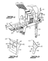
- the corespun yarn 10 includes a core 11 of fibers extending primarily in the axial or longitudinal direction, a core wrapper 12 of fibers surrounding and covering the core 11 and extending primarily in an axial direction, and an outer sheath 13 of fibers surrounding and covering the core wrapper 12 and extending primarily in a circumferential direction.
- the fibers of the core 11 and the core wrapper 12 enhance the tensile strength of the yarn while the fibers of the outer sheath 13 are located on the outer surface of the yarn and provide the desired appearance and general characteristics which are to be imparted to the corespun yarn 10.
- the corespun yarn 10 is produced on a DREF friction spinning apparatus which has been modified in accordance with the present invention, in the manner illustrated in Figures 1-3.
- the friction spinning apparatus includes a core and core wrapper drafting section having a succession of pairs of drafting or draw rolls 20, 21 and 22 with a modified type of entrance trumpet, broadly indicated at 23, positioned adjacent the nip of the first set of drafting rolls 20.
- Conventional trumpets 24 are positioned in the nips of the successive pairs of drafting rolls 21, 22.
- a set of delivery rolls 25 is provided at the exit end of the drafting section and operates to deliver and guide yarn into an elongated throat formed between a pair of perforated suction drums 26, 27 which are rotated in the same direction by a drive belt 28 and a drive pulley 29.
- a plurality of sheath fiber slivers 13 is guided downwardly into draw frame rolls 30, between carding drums 31 and then fed into the elongated throat formed between the pair of perforated suction drums 26, 27 to be wrapped around the outer surface of the yarn.
- the yarn leaves the exit end of the elongated throat between the pair of perforated drums 26, 27, it passes between withdrawing rolls 33 and is directed over and under yarn guides 34, 35 and to the conventional take-up mechanism of the apparatus, not shown.
- the modified entrance yarn trumpet 23 includes a planar, vertically extending, entrance face 36, a lower yarn guide passageway 39 through which the core wrapper sliver 12 is directed, and an upper yarn guide passageway 40 through which the yarn core roving 11 is directed.
- the planar front or entrance face 36 of the entrance trumpet 23 is provided with an integrally formed and outwardly extending horizontal guide rib or bar 42 which serves to maintain separation of the fibers of the core roving 11 and the core wrapper sliver 12 as they move into the entrance ends of the respective guide passageways 40, 39 of the entrance trumpet 23.
- the exit end of the trumpet 23 is provided with inwardly curving converging surfaces 43, 44 conforming substantially to the configuration of the peripheral surfaces of the first pair of draw rolls 20.
- the inwardly curving surfaces 43, 44 are joined together at an outwardly extending apex 45 which is positioned adjacent the nip of the pair of draw rolls 20.
- the forward or entrance ends of the guide passageways 39, 40 are vertically aligned and spaced apart below and above the guide rib 42.
- the exit end of the guide passageway 40 is positioned above and adjacent the exit end of the lower guide passageway 39 so that the core roving 11 is positioned on top of and in the center of the core wrapper sliver 12 as they pass between the nip of the first set of drafting rolls 20.
- the fibers are drawn as they pass through the succession of drafting rolls 20, 21 and 22 of the drafting section and the core wrapper sliver 12 surrounds the fibers of the core 11.
- the fibers of the outer sheath 13 are wrapped around the same in a substantially circumferential direction so that the outer sheath 13 completely surrounds and covers the core wrapper 12 and the core 11.
- the corespun yarn 10 is then removed through the exit end of the friction spinning section by the withdrawing rolls 33 and is directed onto the take-up package, not shown.
- a wide variety of different types of fibers may be utilized to form the core 11, the core wrapper 12, and the outer sheath 13. It has been found that a particularly useful three component corespun yarn can be formed on the friction spinning apparatus of the present invention by feeding a core roving 11 of high temperature resistant fibers into the upper guide passageway 40 of the trumpet 23, feeding a core wrapper sliver 12 of low temperature resistant fibers into the lower guide passageway 39, and feeding a plurality of slivers of low temperature resistant fibers 13 into the draw frame rolls 30. This three component corespun yarn is then woven or knit to form a fabric which is highly useful in the production of fire resistant safety apparel.
- a very effective fire resistant fabric has been formed in accordance with the following nonlimiting example.
- a core roving 11 comprising 40% PBI fibers and 60% Kevlar fibers, and having a weight necessary to achieve 20% in overall yarn weight, is fed into the upper guide passageway 40 of the entrance trumpet 23.
- a core wrapper sliver 12 comprising 100% cotton staple fibers, and having a weight necessary to achieve 30% in overall yarn weight, is fed through the lower guide passageway 39 in the entrance trumpet 23.
- a plurality of outer sheath slivers 13, comprised entirely of cotton fibers, is fed into the draw frame rollers 30 and in an amount sufficient to achieve 50% in overall yarn weight.
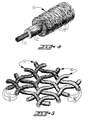
- the resulting corespun yarn 10 is woven into both the warp and filling to form a 155,9 g (5.5 ounce) plain weave fabric, of the type illustrated in Figure 2.
- This woven fabric is dyed and subjected to a topical fire resistant chemical treatment, and a conventional durable press resin finish is then applied thereto.
- the resulting fabric exhibits durable press ratings of 3.0+ after one wash, and 3.0 after five washes. This fabric also exhibits colorfastness when subjected to a carbon arc light source of a 4-5 rating at 40 hours exposure.
- NFPA 701 National Fire Prevention Association test method
- NFPA 701 National Fire Prevention Association test method
- a vertical burn of two 12 second exposures to a high heat flux butane flame shows 22% consumption with zero seconds afterflame, as compared with 45% consumption and 6 seconds afterflame for a 100% Nomex III fabric of similar weight and construction.
- Hot air shrinkage of the corespun fabric was tested in a heated chamber at 242,2°C (468° F.) for five minutes and shrinkage was less than 1% in both warp and filling direction.
- the areas of the fabric char remain flexible and intact, exhibiting no brittleness, melting, or fabric shrinkage.
- the portion of the fabric illustrated in the right-hand portion of Figure 2 is speckled to indicate an area which has been subjected to a burn test and to illustrate the manner in which the low temperature resistant fibers become charred but remain in position surrounding the core of high temperature resistant fibers.
- the charred fibers of the outer sheath 13 and the core wrapper 12 remaining in position around the core 11 provide a thermal insulation barrier and insulating air layer between the skin and the fabric, when the fabric is utilized to form a firefighter's shirt or the like.
- friction spinning apparatus and method of the present invention are not limited to the production of yarn and fabric useful in the production of fire resistant safety apparel of the type set forth above but may be utilized in producing a wide variety of different types of three component corespun yarns, useful in the formation of a wide variety of different types of fabrics.
- the three component corespun yarns produced by the friction spinning apparatus of the present invention each includes a core 11 with the fibers extending primarily in an axial or longitudinal direction of the yarn, a core wrapper 12 of fibers surrounding and covering the core 11 and with the fibers extending primarily in the axial or longitudinal direction of the yarn, and an outer sheath 13 of fibers surrounding and covering the core wrapper 12 and with these fibers extending primarily in a circumferential direction around the corespun yarn 10.
- the feeding of the additional fibers to the friction spinning apparatus is made possible by the provision of an entrance trumpet which includes a pair of guide passageways for directing and maintaining the core fibers and the core wrapper fibers in the proper relationship as they are directed through the drafting section of the friction spinning apparatus.
Landscapes
- Engineering & Computer Science (AREA)
- Mechanical Engineering (AREA)
- Textile Engineering (AREA)
- Spinning Or Twisting Of Yarns (AREA)
- Yarns And Mechanical Finishing Of Yarns Or Ropes (AREA)
- Spinning Methods And Devices For Manufacturing Artificial Fibers (AREA)
Abstract
Description
- This invention relates generally to a friction spinning apparatus and method for forming a three component corespun yarn, and more particularly to such an apparatus and method which includes a trumpet with a pair of guiding passageways for guiding a sliver and roving of fibers into the draw frame section of the apparatus so that these slivers form a core and a core wrapper of the corespun yarn.
- It is known to form a two component corespun yarn on a friction spinning apparatus. For example, U.S. Patent Nos. 4,249,368 and 4,327,545 disclose a DREF type of friction spinning apparatus in which a single sliver of fibers is fed into the entrance end of a draw frame section and then fed through an elongated throat extending between a pair of rotating suction drums where drawn wrapping fibers are fed into the elongated throat and are wound about the fibers extending along the elongated throat to form the two component corespun yarn. U.S. Patent No. 4,107,909 discloses a similar type of friction spinning apparatus in which a core yarn is fed into the elongated throat where drawn wrapping fibers are wrapped about and wound about the core yarn to form a two component corespun yarn. While the types of fibers making up the sliver and/or yarn fed into the draw frame section and the types of fibers making up the drawn wrapping fibers fed into the elongated throat can be varied to form two component corespun yarns with varying characteristics, the number of different types of corespun yarns which may be produced on this known type of friction spinning apparatus is limited.
- With the foregoing in mind, it is an object of the present invention to provide a friction spinning apparatus and method for forming a three component corespun yarn wherein a pair of slivers of fibers is fed into the draw frame section to form a core and a core wrapper surrounding and covering the core, with an outer sheath of drawn wrapping fibers being fed into an elongated throat extending between a pair of rotating suction drums and wrapped around and surrounding the core and the core wrapper. The present apparatus and method makes it possible to produce a wide variety of different types of three component corespun yarns which were not heretofore available.
- In accordance with the present invention, the friction spinning apparatus includes a trumpet positioned adjacent the entrance end of the draw frame section and including a pair of guiding passageways for guiding respective pairs of slivers of fibers into the draw frame section to form a core with a core wrapper surrounding and covering the core. As the core and core wrapper pass through the elongated throat extending between a pair of rotating suction drums, drawn wrapping fibers are fed into the elongated throat and wound about the core and the core wrapper to complete the formation of the three component corespun yarn.
- The pair of guiding passageways extend through the trumpet of the friction spinning apparatus of the present invention and are preferably vertically aligned, one above the other, so that the sliver of core fibers fed through the upper guiding passageway is directed onto the top and in the center of the sliver of core wrapper fibers directed through the lower guiding passageway. The fibers are fed in this position so that the core wrapper fibers surround and cover the core fibers as they are drawn in the draw frame section and pass into the elongated throat extending between the rotating suction drums.
- The trumpet is preferably molded of plastic material and includes an exit end portion having a pair of inwardly curved surfaces joined together at an outwardly extending apex. The inwardly curved surfaces substantially conform to the peripheral surfaces of the first pair of draw rolls of the draw frame section and the apex is positioned adjacent the nip of the first draw rolls in the draw frame section. The exit ends of the guiding passageways terminate at the apex of the trumpet so that the relationship of the slivers of fibers is maintained in a positive manner until the slivers of fibers are passed into the nip between the first pair of draw rolls of the draw frame section. The entrance face of the trumpet is substantially planar and is provided with an integrally molded and outwardly extending horizontal rib extending between the vertically spaced entrance ends of the guiding passageways to aid in preventing migration of fibers from one sliver to the other as they are guided into and through the trumpet.
- The friction spinning apparatus and method of the present invention may be utilized to form a wide variety of different types of three component corespun yarns. For example, the present friction spinning apparatus has been used in the formation of a three component corespun yarn for forming fabric useful in the production of fire resistant safety apparel. This includes a core of high temperature resistant fibers, a core wrapper of low temperature resistant fibers surrounding and covering the core, and an outer sheath of low temperature resistant fibers surrounding and covering the core wrapper. Also, the friction spinning apparatus of the present invention can be utilized in forming a three component corespun yarn in which either the same or different types of fibers can be used to form the core, the core wrapper, and the outer sheath.
- Other objects and advantages will appear as the description proceeds when taken in connection with the accompanying drawings, in which--
- Figure 1 is a fragmentry isometric view of a portion of the friction spinning apparatus of the present invention;
- Figure 2 is an enlarged isometric view of the entrance trumpet, removed from the spinning apparatus, and illustrating the upper and lower guide passageways formed therein;
- Figure 3 is a side elevational view of the entrance trumpet shown in Figure 2;
- Figure 4 is a greatly enlarged view of a fragment of a three component corespun yarn formed on the friction spinning apparatus of the present invention and illustrating portions of the outer sheath and core wrapper being removed at one end portion thereof; and
- Figure 5 is a greatly enlarged isometric view of a fragmentry portion of a fabric woven of the yarn of Figure 1, with the right-hand portion having been exposed to a flame.
- One type of three component corespun yarn, broadly indicated at 10, which may be produced by the friction spinning apparatus and method of the present invention is illustrated in Figure 4. The
corespun yarn 10 includes a core 11 of fibers extending primarily in the axial or longitudinal direction, acore wrapper 12 of fibers surrounding and covering the core 11 and extending primarily in an axial direction, and an outer sheath 13 of fibers surrounding and covering thecore wrapper 12 and extending primarily in a circumferential direction. The fibers of the core 11 and thecore wrapper 12 enhance the tensile strength of the yarn while the fibers of the outer sheath 13 are located on the outer surface of the yarn and provide the desired appearance and general characteristics which are to be imparted to thecorespun yarn 10. - The
corespun yarn 10 is produced on a DREF friction spinning apparatus which has been modified in accordance with the present invention, in the manner illustrated in Figures 1-3. The friction spinning apparatus includes a core and core wrapper drafting section having a succession of pairs of drafting ordraw rolls drafting rolls 20. Conventional trumpets 24 are positioned in the nips of the successive pairs ofdrafting rolls delivery rolls 25 is provided at the exit end of the drafting section and operates to deliver and guide yarn into an elongated throat formed between a pair of perforatedsuction drums 26, 27 which are rotated in the same direction by adrive belt 28 and adrive pulley 29. - A plurality of sheath fiber slivers 13 is guided downwardly into draw frame rolls 30, between carding drums 31 and then fed into the elongated throat formed between the pair of perforated
suction drums 26, 27 to be wrapped around the outer surface of the yarn. As the yarn leaves the exit end of the elongated throat between the pair ofperforated drums 26, 27, it passes between withdrawing rolls 33 and is directed over and underyarn guides 34, 35 and to the conventional take-up mechanism of the apparatus, not shown. - As illustrated in Figures 2 and 3, the modified
entrance yarn trumpet 23 includes a planar, vertically extending,entrance face 36, a loweryarn guide passageway 39 through which thecore wrapper sliver 12 is directed, and an upperyarn guide passageway 40 through which the yarn core roving 11 is directed. The planar front orentrance face 36 of theentrance trumpet 23 is provided with an integrally formed and outwardly extending horizontal guide rib orbar 42 which serves to maintain separation of the fibers of the core roving 11 and thecore wrapper sliver 12 as they move into the entrance ends of therespective guide passageways entrance trumpet 23. The exit end of thetrumpet 23 is provided with inwardly curvingconverging surfaces draw rolls 20. The inwardly curvingsurfaces apex 45 which is positioned adjacent the nip of the pair ofdraw rolls 20. - The forward or entrance ends of the
guide passageways guide rib 42. The exit end of theguide passageway 40 is positioned above and adjacent the exit end of thelower guide passageway 39 so that the core roving 11 is positioned on top of and in the center of thecore wrapper sliver 12 as they pass between the nip of the first set ofdrafting rolls 20. The fibers are drawn as they pass through the succession ofdrafting rolls core wrapper sliver 12 surrounds the fibers of the core 11. - As the core wrapper 12 and the core 11 move forwardly from the
delivery rolls 25 and through the friction spinning section formed by the elongated throat between the perforated rotatingsuction drums 26, 27, the fibers of the outer sheath 13 are wrapped around the same in a substantially circumferential direction so that the outer sheath 13 completely surrounds and covers thecore wrapper 12 and the core 11. Thecorespun yarn 10 is then removed through the exit end of the friction spinning section by the withdrawing rolls 33 and is directed onto the take-up package, not shown. - A wide variety of different types of fibers may be utilized to form the core 11, the
core wrapper 12, and the outer sheath 13. It has been found that a particularly useful three component corespun yarn can be formed on the friction spinning apparatus of the present invention by feeding a core roving 11 of high temperature resistant fibers into theupper guide passageway 40 of thetrumpet 23, feeding acore wrapper sliver 12 of low temperature resistant fibers into thelower guide passageway 39, and feeding a plurality of slivers of low temperature resistant fibers 13 into the draw frame rolls 30. This three component corespun yarn is then woven or knit to form a fabric which is highly useful in the production of fire resistant safety apparel. - For example, a very effective fire resistant fabric has been formed in accordance with the following nonlimiting example. A core roving 11 comprising 40% PBI fibers and 60% Kevlar fibers, and having a weight necessary to achieve 20% in overall yarn weight, is fed into the
upper guide passageway 40 of theentrance trumpet 23. Acore wrapper sliver 12 comprising 100% cotton staple fibers, and having a weight necessary to achieve 30% in overall yarn weight, is fed through thelower guide passageway 39 in theentrance trumpet 23. A plurality of outer sheath slivers 13, comprised entirely of cotton fibers, is fed into the draw frame rollers 30 and in an amount sufficient to achieve 50% in overall yarn weight. - The resulting
corespun yarn 10 is woven into both the warp and filling to form a 155,9 g (5.5 ounce) plain weave fabric, of the type illustrated in Figure 2. This woven fabric is dyed and subjected to a topical fire resistant chemical treatment, and a conventional durable press resin finish is then applied thereto. The resulting fabric exhibits durable press ratings of 3.0+ after one wash, and 3.0 after five washes. This fabric also exhibits colorfastness when subjected to a carbon arc light source of a 4-5 rating at 40 hours exposure. This fabric is then subjected to a National Fire Prevention Association test method (NFPA 701) which involves a vertical burn of 12 second duration to a Bunsen burner flame, and the fabric exhibits char lengths of less than 3,8 cm (1.5 inches) with no afterflame or afterglow. In accordance with Federal Test Method 5905, a vertical burn of two 12 second exposures to a high heat flux butane flame shows 22% consumption with zero seconds afterflame, as compared with 45% consumption and 6 seconds afterflame for a 100% Nomex III fabric of similar weight and construction. Hot air shrinkage of the corespun fabric was tested in a heated chamber at 242,2°C (468° F.) for five minutes and shrinkage was less than 1% in both warp and filling direction. - Throughout all burn tests, the areas of the fabric char remain flexible and intact, exhibiting no brittleness, melting, or fabric shrinkage. The portion of the fabric illustrated in the right-hand portion of Figure 2 is speckled to indicate an area which has been subjected to a burn test and to illustrate the manner in which the low temperature resistant fibers become charred but remain in position surrounding the core of high temperature resistant fibers. The charred fibers of the outer sheath 13 and the
core wrapper 12 remaining in position around the core 11 provide a thermal insulation barrier and insulating air layer between the skin and the fabric, when the fabric is utilized to form a firefighter's shirt or the like. - It is to be understood that the friction spinning apparatus and method of the present invention are not limited to the production of yarn and fabric useful in the production of fire resistant safety apparel of the type set forth above but may be utilized in producing a wide variety of different types of three component corespun yarns, useful in the formation of a wide variety of different types of fabrics. The three component corespun yarns produced by the friction spinning apparatus of the present invention each includes a core 11 with the fibers extending primarily in an axial or longitudinal direction of the yarn, a
core wrapper 12 of fibers surrounding and covering the core 11 and with the fibers extending primarily in the axial or longitudinal direction of the yarn, and an outer sheath 13 of fibers surrounding and covering thecore wrapper 12 and with these fibers extending primarily in a circumferential direction around thecorespun yarn 10. The feeding of the additional fibers to the friction spinning apparatus is made possible by the provision of an entrance trumpet which includes a pair of guide passageways for directing and maintaining the core fibers and the core wrapper fibers in the proper relationship as they are directed through the drafting section of the friction spinning apparatus. - In the drawings and specification there has been set forth the best mode presently contemplated for the practice of the present invention, and although specific terms are employed, they are used in a generic and descriptive sense only and not for purposes of limitation, the scope of the invention being defined in the claims.
Claims (6)
- A friction spinning apparatus for forming a corespun yarn comprising a pair of adjacent rotatable suction drums 26, 27 defining an elongated throat extending between said suction drums 26, 27 and including entrance and exit ends, a draw frame section 20, 21, 22, 25 including entrance and exit ends and with said exit end 25 being positioned adjacent said entrance end of said elongated throat extending between said suction drums 26, 27, trumpet means 23 positioned adjacent said entrance end of said draw frame section 20, 21, 22, 25 and including a first guiding passageway 39 for guiding a sliver of fibers 12 into said draw frame section 20, 21, 22, 25 yarn withdrawal means 33 positioned adjacent said exit end of said elongated throat, and roller drawing frame means 30, 31 including entrance and exit ends, said roller drawing frame means 30, 31 being positioned adjacent said elongate throat and being operable to receive slivers of fibers 13 in said entrance end thereof and to feed drawn wrapping fibers 13 into said elongated throat so that said wrapping fibers 13 are wound about the fibers 12 extending along said elongated throat, characterized by means for feeding an additional sliver of fibers 11 to said draw frame section 20, 21, 22, 25 to form a three component corespun yarn 10, said additional fiber feeding means comprising an additional sliver guiding passageway 40 in said trumpet means 23 and positioned adjacent said first sliver guiding passageway 39 for directing the additional sliver 11 into the central portion of the sliver 12 passing through said first sliver guiding passageway 39 of said trumpet means 23 so that said first and additional slivers pass therethrough and are drafted in said draw frame section 20, 21, 22, 25 with the first sliver 12 surrounding said additional sliver 11, and wherein the fibers 13 from said roller drawing frame means 30, 31 are wrapped around the first 12 and additional 11 slivers passing through said elongated throat to form the three component corespun yarn 10.
- A friction spinning apparatus according to Claim 1, characterised in that said trumpet means 23 includes a planar entrance face 36 and an exit end, said exit end including a pair of inwardly curved surfaces 43, 44 joined together at an outwardly extending apex 45, said first guiding passageway 39 and said additional guiding passageway 40 in said trumpet means 23 each includes an entrance end in said planar entrance face 36, and an exit end adjacent said outwardly extending apex 45, and wherein said entrance ends are spaced apart and in vertical alignment on said planar entrance face 36.
- A friction spinning apparatus according to Claim 2 characterised in that said exit ends of said first guiding passageway 39 and said additional guiding passageways 40 are positioned adjacent each other at said outwardly extending apex 45 of said trumpet means 23.
- A friction spinning apparatus according to Claim 3 characterised in that said planar entrance face 36 of said trumpet means 23 includes a horizontally extending guide rib 42 extending outwardly from said planar entrance face 36 and between said spaced-apart entrance ends of said first guiding passageway 39 and said additional guiding passageway 40 to aid in maintaining separation of the fibers of the slivers guided into and through said guiding passageways 39, 40.
- A friction spinning apparatus according to any one of claims 2 to 4 characterised in that said draw frame section 20, 21, 22, 25 includes successive pairs of draw rolls defining nips therebetween, and wherein said inwardly curved surfaces 43, 44 of said exit end of said trumpet means 23 substantially conform to the peripheral surfaces of the first (20) of said pairs of draw rolls and said outwardly extending apex 45 of said trumpet means 23 is positioned adjacent the nip of said first 20 pair of draw rolls.
- A method of friction spinning a three component corespun yarn comprises
separately guiding first and second slivers of fibers via guide passageways to a draw frame and drafting said slivers together in said draw frame so that the first slivers surround the second slivers and subsequently wrapping the drafted slivers with wrapping fibers.
Priority Applications (1)
| Application Number | Priority Date | Filing Date | Title |
|---|---|---|---|
| AT89309152T ATE89042T1 (en) | 1988-12-22 | 1989-09-08 | FRICTION SPINNING DEVICE AND PROCESS FOR MAKING CORE YARN. |
Applications Claiming Priority (2)
| Application Number | Priority Date | Filing Date | Title |
|---|---|---|---|
| US288767 | 1988-12-22 | ||
| US07/288,767 US4860530A (en) | 1988-12-22 | 1988-12-22 | Corespun yarn friction spinning apparatus and method |
Publications (3)
| Publication Number | Publication Date |
|---|---|
| EP0375112A2 EP0375112A2 (en) | 1990-06-27 |
| EP0375112A3 EP0375112A3 (en) | 1990-12-05 |
| EP0375112B1 true EP0375112B1 (en) | 1993-05-05 |
Family
ID=23108554
Family Applications (1)
| Application Number | Title | Priority Date | Filing Date |
|---|---|---|---|
| EP89309152A Expired - Lifetime EP0375112B1 (en) | 1988-12-22 | 1989-09-08 | Corespun yarn friction spinning apparatus and method |
Country Status (9)
| Country | Link |
|---|---|
| US (1) | US4860530A (en) |
| EP (1) | EP0375112B1 (en) |
| JP (1) | JPH0684569B2 (en) |
| KR (1) | KR930008380B1 (en) |
| CN (1) | CN1020769C (en) |
| AT (1) | ATE89042T1 (en) |
| AU (1) | AU618918B2 (en) |
| CA (1) | CA1319573C (en) |
| DE (1) | DE68906369D1 (en) |
Families Citing this family (16)
| Publication number | Priority date | Publication date | Assignee | Title |
|---|---|---|---|---|
| US5033262A (en) * | 1988-12-22 | 1991-07-23 | Springs Industries, Inc. | Method of forming a corespun yarn for fire resistant safety apparel |
| CA2044378A1 (en) * | 1990-10-02 | 1992-04-03 | Mitsuo Matsumoto | Shock-absorbing air bag |
| US5802826A (en) * | 1993-08-06 | 1998-09-08 | The United States Of America As Represented By The Secretary Of Agriculture | Production of core/wrap yarns by airjet and friction spinning in tandem |
| DE19601038A1 (en) * | 1996-01-13 | 1997-07-17 | Fritz Stahlecker | OE-spinning process giving good twist and discharge speed control |
| GB9806622D0 (en) * | 1998-03-30 | 1998-05-27 | Univ Leeds | Friction spinning machine |
| US6637085B2 (en) * | 2001-10-26 | 2003-10-28 | E. I. Du Pont De Nemours And Company | Process for recycling articles containing high-performance fiber |
| WO2007054827A2 (en) * | 2005-10-17 | 2007-05-18 | Mandawewala Rajesh R | Hygro materials for use in making yarns and fabrics |
| CN102011228B (en) * | 2010-11-05 | 2013-01-02 | 广州纺织服装研究院 | Rough yarn strip fascinated yarn and spinning device and spinning method thereof |
| CN102021683A (en) * | 2010-12-30 | 2011-04-20 | 山东宏业纺织股份有限公司 | Roving frame and processing method of siro spinning using same |
| CN104762704B (en) * | 2015-03-19 | 2017-09-15 | 上海工程技术大学 | A kind of Performances of Novel Nano-Porous meter level electrostatic friction spinning apparatus |
| CN105220246B (en) * | 2015-08-31 | 2017-11-24 | 中原工学院 | A kind of multiply jet friction of electrostatic spinning nano fiber is into yarn feeding device and preparation method |
| US9828704B2 (en) | 2015-09-10 | 2017-11-28 | Welspun India Limited | Terry article with synthetic filament yarns and method of making same |
| EP3914760A4 (en) * | 2019-01-22 | 2022-11-16 | Mpusa, LLC | DUAL FUNCTION YARN FILAMENT WOVEN TERRY COOLING TOWEL |
| CN114908451B (en) * | 2022-02-23 | 2024-03-22 | 江苏工程职业技术学院 | Spinning method of staple yarn core ring spindle core spun yarn based on drawing process |
| CN117552132A (en) * | 2023-12-21 | 2024-02-13 | 无锡舟控客电子设备有限公司 | A kind of velvet yarn spinning equipment |
| CN117802639A (en) * | 2024-01-03 | 2024-04-02 | 东台市华源复合材料有限公司 | An air friction spinning machine for core-spun yarn processing |
Family Cites Families (9)
| Publication number | Priority date | Publication date | Assignee | Title |
|---|---|---|---|---|
| US3092953A (en) * | 1960-08-01 | 1963-06-11 | Bear Brand Hosiery Co | Method and apparatus for forming yarn |
| US3370410A (en) * | 1965-01-29 | 1968-02-27 | Caron Spinning Company | Spinning device |
| US4041690A (en) * | 1975-11-05 | 1977-08-16 | Tuscarora Cotton Mill | Novelty yarn and method for making same |
| AT339779B (en) * | 1976-04-08 | 1977-11-10 | Fehrer Ernst Gmbh | DEVICE FOR SPINNING TEXTILE FIBERS |
| DE2909615C2 (en) * | 1978-05-26 | 1982-03-18 | Ernst Dr. 4020 Linz Fehrer | Apparatus for producing a yarn |
| DE3023936A1 (en) * | 1979-07-27 | 1981-02-19 | Ernst Dr Fehrer | DEVICE FOR PRODUCING A YARN |
| AT381510B (en) * | 1985-04-23 | 1986-10-27 | Fehrer Ernst | Apparatus for producing a yarn |
| US4711079A (en) * | 1986-01-31 | 1987-12-08 | Burlington Industries, Inc. | Roving blending for making sheath/core spun yarn |
| AT384039B (en) * | 1986-03-07 | 1987-09-25 | Fehrer Ernst | Apparatus for the production of a yarn |
-
1988
- 1988-12-22 US US07/288,767 patent/US4860530A/en not_active Expired - Lifetime
-
1989
- 1989-09-08 EP EP89309152A patent/EP0375112B1/en not_active Expired - Lifetime
- 1989-09-08 AT AT89309152T patent/ATE89042T1/en not_active IP Right Cessation
- 1989-09-08 DE DE8989309152T patent/DE68906369D1/en not_active Expired - Lifetime
- 1989-09-14 CA CA000611362A patent/CA1319573C/en not_active Expired - Fee Related
- 1989-09-14 AU AU41315/89A patent/AU618918B2/en not_active Ceased
- 1989-10-16 JP JP1266363A patent/JPH0684569B2/en not_active Expired - Fee Related
- 1989-12-22 KR KR1019890019329A patent/KR930008380B1/en not_active Expired - Fee Related
- 1989-12-22 CN CN89109810A patent/CN1020769C/en not_active Expired - Fee Related
Also Published As
| Publication number | Publication date |
|---|---|
| JPH02175928A (en) | 1990-07-09 |
| DE68906369D1 (en) | 1993-06-09 |
| EP0375112A3 (en) | 1990-12-05 |
| EP0375112A2 (en) | 1990-06-27 |
| KR930008380B1 (en) | 1993-08-31 |
| US4860530A (en) | 1989-08-29 |
| AU618918B2 (en) | 1992-01-09 |
| ATE89042T1 (en) | 1993-05-15 |
| KR900010096A (en) | 1990-07-06 |
| CN1044834A (en) | 1990-08-22 |
| JPH0684569B2 (en) | 1994-10-26 |
| CA1319573C (en) | 1993-06-29 |
| AU4131589A (en) | 1990-06-28 |
| CN1020769C (en) | 1993-05-19 |
Similar Documents
| Publication | Publication Date | Title |
|---|---|---|
| US4958485A (en) | Corespun yarn for fire resistant safety apparel | |
| US5033262A (en) | Method of forming a corespun yarn for fire resistant safety apparel | |
| EP0375112B1 (en) | Corespun yarn friction spinning apparatus and method | |
| US5572860A (en) | Fusible adhesive yarn | |
| US2132702A (en) | Combined asbestos and glass fiber yarn | |
| EP0745151A1 (en) | Core/wrap yarn | |
| JP7286122B2 (en) | Spun yarn and its manufacturing method | |
| KR101334886B1 (en) | Core yarn having excellent coverage ratio and flexibility, manufacturing method thereof, and manufacturing device thereof | |
| CA1062564A (en) | Method of making core yarn | |
| RU2402649C1 (en) | Heat resistant sewing thread and method of its manufacturing | |
| KR102403772B1 (en) | Manufacturing Method Of Modacrylic/Tencell Airjet Spun Yarn Having Excellent Fire Retardant | |
| JPH0978379A (en) | Core-sheath composite spun yarn and knitted fabric using the same | |
| JPS6331568B2 (en) | ||
| JPS63227820A (en) | Production of fire-and heat-resistant conjugate spun yarn | |
| JPH09157983A (en) | Manufacturing method of composite yarn | |
| JPH0635689B2 (en) | Method of manufacturing composite yarn | |
| JPH10280239A (en) | Composite spun yarn, method for producing the same, and fabric | |
| CN117265727A (en) | Core-spun yarn and preparation method thereof, and preparation method of knitted wool fabric | |
| CN118756391A (en) | Core-spun yarn and preparation method thereof and washable stable flame-retardant fabric | |
| JP3502483B2 (en) | Method for producing false twisted composite yarn | |
| JPS5847486B2 (en) | Manufacturing method of special bulky yarn | |
| JPS62162038A (en) | Polyamide coated elastic yarn and its production | |
| CN117693616A (en) | Multi-layer structured short fiber yarn, manufacturing method thereof, heat-resistant fabric and heat-resistant protective clothing | |
| GB2080847A (en) | Unspun yarn | |
| JPH055225A (en) | Method for stretch-breaking fiber bundle |
Legal Events
| Date | Code | Title | Description |
|---|---|---|---|
| PUAI | Public reference made under article 153(3) epc to a published international application that has entered the european phase |
Free format text: ORIGINAL CODE: 0009012 |
|
| AK | Designated contracting states |
Kind code of ref document: A2 Designated state(s): AT BE CH DE ES FR GB GR IT LI LU NL SE |
|
| PUAL | Search report despatched |
Free format text: ORIGINAL CODE: 0009013 |
|
| AK | Designated contracting states |
Kind code of ref document: A3 Designated state(s): AT BE CH DE ES FR GB GR IT LI LU NL SE |
|
| 17P | Request for examination filed |
Effective date: 19901116 |
|
| 17Q | First examination report despatched |
Effective date: 19920623 |
|
| GRAA | (expected) grant |
Free format text: ORIGINAL CODE: 0009210 |
|
| AK | Designated contracting states |
Kind code of ref document: B1 Designated state(s): AT BE CH DE ES FR GB GR IT LI LU NL SE |
|
| PG25 | Lapsed in a contracting state [announced via postgrant information from national office to epo] |
Ref country code: IT Free format text: LAPSE BECAUSE OF FAILURE TO SUBMIT A TRANSLATION OF THE DESCRIPTION OR TO PAY THE FEE WITHIN THE PRE;WARNING: LAPSES OF ITALIAN PATENTS WITH EFFECTIVE DATE BEFORE 2007 MAY HAVE OCCURRED AT ANY TIME BEFORE 2007. THE CORRECT EFFECTIVE DATE MAY BE DIFFERENT FROM THE ONE RECORDED.SCRIBED TIME-LIMIT Effective date: 19930505 Ref country code: LI Effective date: 19930505 Ref country code: FR Effective date: 19930505 Ref country code: AT Effective date: 19930505 Ref country code: NL Effective date: 19930505 Ref country code: SE Effective date: 19930505 Ref country code: BE Effective date: 19930505 Ref country code: CH Effective date: 19930505 Ref country code: GR Free format text: LAPSE BECAUSE OF FAILURE TO SUBMIT A TRANSLATION OF THE DESCRIPTION OR TO PAY THE FEE WITHIN THE PRESCRIBED TIME-LIMIT Effective date: 19930505 Ref country code: DE Effective date: 19930505 Ref country code: ES Free format text: THE PATENT HAS BEEN ANNULLED BY A DECISION OF A NATIONAL AUTHORITY Effective date: 19930505 |
|
| REF | Corresponds to: |
Ref document number: 89042 Country of ref document: AT Date of ref document: 19930515 Kind code of ref document: T |
|
| REF | Corresponds to: |
Ref document number: 68906369 Country of ref document: DE Date of ref document: 19930609 |
|
| REG | Reference to a national code |
Ref country code: CH Ref legal event code: PL |
|
| PG25 | Lapsed in a contracting state [announced via postgrant information from national office to epo] |
Ref country code: GB Effective date: 19930908 |
|
| EN | Fr: translation not filed | ||
| PG25 | Lapsed in a contracting state [announced via postgrant information from national office to epo] |
Ref country code: LU Free format text: LAPSE BECAUSE OF NON-PAYMENT OF DUE FEES Effective date: 19930930 |
|
| NLV1 | Nl: lapsed or annulled due to failure to fulfill the requirements of art. 29p and 29m of the patents act | ||
| PLBE | No opposition filed within time limit |
Free format text: ORIGINAL CODE: 0009261 |
|
| STAA | Information on the status of an ep patent application or granted ep patent |
Free format text: STATUS: NO OPPOSITION FILED WITHIN TIME LIMIT |
|
| 26N | No opposition filed | ||
| GBPC | Gb: european patent ceased through non-payment of renewal fee |
Effective date: 19930908 |