EP0375150A2 - Dispositif compact de chauffage pour un applicateur de produit thermofusible - Google Patents
Dispositif compact de chauffage pour un applicateur de produit thermofusible Download PDFInfo
- Publication number
- EP0375150A2 EP0375150A2 EP89311876A EP89311876A EP0375150A2 EP 0375150 A2 EP0375150 A2 EP 0375150A2 EP 89311876 A EP89311876 A EP 89311876A EP 89311876 A EP89311876 A EP 89311876A EP 0375150 A2 EP0375150 A2 EP 0375150A2
- Authority
- EP
- European Patent Office
- Prior art keywords
- melting chamber
- heating elements
- outlet
- assembly
- heating
- Prior art date
- Legal status (The legal status is an assumption and is not a legal conclusion. Google has not performed a legal analysis and makes no representation as to the accuracy of the status listed.)
- Granted
Links
Images

Classifications
-
- B—PERFORMING OPERATIONS; TRANSPORTING
- B05—SPRAYING OR ATOMISING IN GENERAL; APPLYING FLUENT MATERIALS TO SURFACES, IN GENERAL
- B05C—APPARATUS FOR APPLYING FLUENT MATERIALS TO SURFACES, IN GENERAL
- B05C21/00—Accessories or implements for use in connection with applying liquids or other fluent materials to surfaces, not provided for in groups B05C1/00 - B05C19/00
-
- B—PERFORMING OPERATIONS; TRANSPORTING
- B05—SPRAYING OR ATOMISING IN GENERAL; APPLYING FLUENT MATERIALS TO SURFACES, IN GENERAL
- B05C—APPARATUS FOR APPLYING FLUENT MATERIALS TO SURFACES, IN GENERAL
- B05C17/00—Hand tools or apparatus using hand held tools, for applying liquids or other fluent materials to, for spreading applied liquids or other fluent materials on, or for partially removing applied liquids or other fluent materials from, surfaces
- B05C17/005—Hand tools or apparatus using hand held tools, for applying liquids or other fluent materials to, for spreading applied liquids or other fluent materials on, or for partially removing applied liquids or other fluent materials from, surfaces for discharging material from a reservoir or container located in or on the hand tool through an outlet orifice by pressure without using surface contacting members like pads or brushes
- B05C17/00523—Hand tools or apparatus using hand held tools, for applying liquids or other fluent materials to, for spreading applied liquids or other fluent materials on, or for partially removing applied liquids or other fluent materials from, surfaces for discharging material from a reservoir or container located in or on the hand tool through an outlet orifice by pressure without using surface contacting members like pads or brushes provided with means to heat the material
- B05C17/00546—Details of the heating means
Definitions
- This invention relates to a heater assembly for melting and dispensing hot melt adhesives and similar materials.
- Hot melt adhesives are widely used for a variety of purposes ranging from industrial to household applications. Often, hot melt adhesives are dispensed by a hand-held applicator which may be conveniently manipulated to deliver molten adhesive directly to an application site. Applicators of this type normally have a heated melting chamber of a truncated cone shape that is adapted to receive and melt elongated blocks of solid thermoplastic adhesive and dispense the molten adhesive through an outlet.
- Melting chambers of hot melt applicators are formed within a heating block that is made of metallic materials exhibiting a high thermal conductivity.
- these heating blocks have a cylindrical compartment that is below the melting chamber and which receives a slide-in electrical heating element having an elongated external casing of matching cylindrical shape.
- the single heating element of such heater assemblies extends in a direction that is either parallel or somewhat inclined relative to the central longitudinal axis of the truncated conical melting chamber.
- Heater assemblies of hot melt applicators are occasionally provided with two or more heating elements in an attempt to increase the available thermal energy and to improve heat distribution to the melting chamber.
- elongated heating elements are located on opposite sides of the melting chamber in an orientation such that the longitudinal axis of each heater and the central axis of the melting chamber all extend in parallel directions in a common plane.
- such construction requires a somewhat bulky heating block which increases the weight of the applicator and hinders observation of the work site.
- the present invention is directed toward a heater assembly for a hot melt applicator which includes a heating block made of a material having a relatively high thermal conductivity and having a melting chamber with an inlet and an outlet.
- the melting chamber has a generally truncated conical shape tapering toward the outlet along a central reference axis.
- the heating block has a pair of conical compartments disposed along opposite sides of the melting chamber.
- a pair of elongated heating elements are disposed in respective compartments and have a conical external configuration complemental to the compartments.
- the compartments and the heating elements have respective longitudinal axes which generally lie in a common plane that extends toward the outlet at an angle in the range of about 1 degree to about 16 degrees relative to the reference axis.
- the configuration of the heater assembly presents a relatively small profile which facilitates observation of the work.
- the compact heater assembly is relatively light in weight which reduces the likelihood of operator fatigue that might otherwise occur when the applicator is held in the hand for extended periods.
- the angular orientation of the heating elements relative to the melting chamber also enables the heating elements to efficiently deliver thermal energy to the entire perimeter of the melting chamber.
- a hot melt applicator 10 as illustrated in Fig. 1 includes a housing 12 with a handle 14, along with a feed mechanism 16 adapted to releasably grasp a solid, elongated block of thermoplastic material.
- the feed mechanism 16 includes an actuator 18 that, when depressed in a direction toward the handle 14, directs the block of material toward a heater assembly 20 which is substantially enclosed within the housing 12.
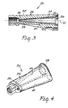
- the heater assembly 20 is adapted to receive and melt a forward end portion of the block of material and dispense the molten material through a front nozzle 22 to an application site.
- the heater assembly 20 includes a unitary heat block 24 that is made from a material exhibiting high thermal conductivity such as aluminum.
- the heating block 24 has an internal, central melting chamber 26 with an inlet 28 at one end and a somewhat smaller outlet 30 at an opposite end (see, e.g., Fig. 3).
- the melting chamber 26 has an overall, generally truncated conical shape which tapers toward the outlet 30 along a central reference axis 32.
- the heating block 24 is also formed with four symmetrically arranged grooves 34 which extend along the melting chamber 26 from the inlet 28 to the outlet 30 and which gradually increase in depth as the outlet 30 is approached.
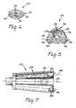
- the heater assembly 20 includes two elongated heating elements 36, 38 (Fig. 7) that are thermally coupled to the heating block 24 and are disposed along opposite sides of the melting chamber 26.
- the heating elements 36, 38 have an external shape in the form of a truncated cone, and are received in respective, similarly shaped compartments 40, 42 (Figs. 2 and 4-6) formed in the heating block 24.
- the heating elements 36, 38 have respective longitudinal axes 44, 46 that generally lie in a common plane which is indicated in Fig. 2 by the numeral 48.
- the plane 48 containing the axes 44, 46 extends toward the outlet 30 at an angle 56 (see Fig. 2) in the range of about 1 degree to about 16 degrees relative to the central reference axis 32 of the melting chamber 26. Somewhat better results are observed when the angle 56 is in the range of about 3 degrees to about 12 degrees. Moreover, the axes 44, 46 converge toward each other as well as toward the central reference axis 32 as illustrated in Fig. 7 as the outlet 30 is approached. As shown in Fig. 5, a reference line 50 extending between respective forward end portions of the heating elements 36, 38 and along the plane 48 passes outside of the melting chamber 26. Also, an upper wall section 52 (see Fig. 3) of the heating block 24 above the melting chamber 26 is thicker in cross section (in a vertical direction viewing Fig. 3) than an underlying wall section 54 of the heating block 24 below the melting chamber 26.
- the angle 56 between the plane 48 and the axis 32 may vary somewhat for optimum results depending upon the desired length of the heating block 24 and the diameter of the solid material to be fed into the melting chamber 26.
- the angle 56 should be in the range of about 3 degrees to about 7 degrees. If, on the other hand, the overall diameter of the solid material is about 0.625 inch (1.59 cm.), the angle 56 should be in the range of about 6 degrees to about 10 degrees.
- the angle 56 should be in the range of about 8 degrees to about 12 degrees.
- Construction of the heater assembly 20 in accordance with the foregoing provides efficient heat distribution from the heating elements 36, 38 to the melting chamber 26 around substantially the entire perimeter of the latter.
- the wall section 52 being thicker than the wall section 54, facilitates the distribution of heat to upper reaches of the melting chamber 26 which are disposed somewhat farther away from the heating elements 36, 38 than underlying regions of the heating block 24 such as wall section 54.
- the generally overall conical configuration of the heating elements 36, 38 is advantageous in that the forward end profile of the heating block 24 can be reduced even though the forward and portions of the heating elements 36, 38 extend upwardly toward the melting chamber 26 and terminate at respective locations approximately 180 degrees apart relative to the melting chamber 26 as depicted in Fig. 6.
- electrical resistance wires within the heating elements 36, 38 are constructed or arranged to provide selected quantities of thermal energy per unit length of the elements 36, 38 that vary along the respective lengths of the elements 36, 38.
- rear portions of the elements 36, 38 adjacent the rear end portion of the melting chamber 26 near the inlet 28 are constructed to deliver greater heat output (per unit length) than front portions of the elements 36, 38 adjacent the front end portion of the chamber 26 near the outlet 30. This construction facilitates melting the solid adhesive in the rear end portion of the chamber 26 and reduces the likelihood of overheating the molten adhesive during passage through the front end portion of the chamber.
Landscapes
- Engineering & Computer Science (AREA)
- Mechanical Engineering (AREA)
- Coating Apparatus (AREA)
- Adhesives Or Adhesive Processes (AREA)
- Particle Formation And Scattering Control In Inkjet Printers (AREA)
Applications Claiming Priority (2)
| Application Number | Priority Date | Filing Date | Title |
|---|---|---|---|
| US07/286,653 US4948944A (en) | 1988-12-19 | 1988-12-19 | Compact heater assembly for a hot melt applicator |
| US286653 | 1988-12-19 |
Publications (3)
| Publication Number | Publication Date |
|---|---|
| EP0375150A2 true EP0375150A2 (fr) | 1990-06-27 |
| EP0375150A3 EP0375150A3 (fr) | 1991-04-24 |
| EP0375150B1 EP0375150B1 (fr) | 1994-01-05 |
Family
ID=23099566
Family Applications (1)
| Application Number | Title | Priority Date | Filing Date |
|---|---|---|---|
| EP89311876A Expired - Lifetime EP0375150B1 (fr) | 1988-12-19 | 1989-11-16 | Dispositif compact de chauffage pour un applicateur de produit thermofusible |
Country Status (8)
| Country | Link |
|---|---|
| US (1) | US4948944A (fr) |
| EP (1) | EP0375150B1 (fr) |
| JP (1) | JPH0737741Y2 (fr) |
| KR (1) | KR950000229Y1 (fr) |
| AU (1) | AU624653B2 (fr) |
| BR (1) | BR8906582A (fr) |
| CA (1) | CA2003680A1 (fr) |
| DE (1) | DE68912101T2 (fr) |
Cited By (1)
| Publication number | Priority date | Publication date | Assignee | Title |
|---|---|---|---|---|
| WO2009109393A1 (fr) * | 2008-03-06 | 2009-09-11 | Steinel Gmbh | Dispositif d’application de matières adhésives |
Families Citing this family (9)
| Publication number | Priority date | Publication date | Assignee | Title |
|---|---|---|---|---|
| US5688421A (en) * | 1991-10-11 | 1997-11-18 | Walton; William M. | Dispenser for heat-liquefiable material with contiguous PTC heater and heat exchanging member |
| US5236269A (en) * | 1993-01-14 | 1993-08-17 | Mattel, Inc. | Battery-powered dispenser for hot melt adhesive |
| US5462206A (en) * | 1994-10-12 | 1995-10-31 | Kwasie; Jon B. | Melting assembly for thermoplastic materials |
| USD414663S (en) | 1998-06-16 | 1999-10-05 | Uniplast, Inc. | Feeder handle for a hot glue gun |
| USD412432S (en) * | 1998-06-16 | 1999-08-03 | Uniplast, Inc. | Hot glue gun with removable cartridge |
| USD412650S (en) | 1998-06-16 | 1999-08-10 | Uniplast, Inc. | Removable cartridge for a hot glue gun |
| US6230936B1 (en) * | 1998-12-23 | 2001-05-15 | Bernard C. Lasko | Folded susceptor for glue gun |
| TWD152231S (zh) * | 2011-08-31 | 2013-03-11 | 素路彩米克斯派克股份有限公司 | 配送器 |
| USD998434S1 (en) * | 2021-12-02 | 2023-09-12 | Adhesive Technologies, Inc. | Thumb feed glue gun |
Family Cites Families (10)
| Publication number | Priority date | Publication date | Assignee | Title |
|---|---|---|---|---|
| US3743142A (en) * | 1971-10-08 | 1973-07-03 | Usm Corp | Adhesive extruders |
| US3776426A (en) * | 1972-09-26 | 1973-12-04 | Usm Corp | Adhesive extruders |
| US4014464A (en) * | 1975-12-09 | 1977-03-29 | Usm Corporation | Hot melt dispenser and method of making its melt body |
| US4050890A (en) * | 1976-04-12 | 1977-09-27 | Usm Corporation | Hot melt dispenser body |
| US4059204A (en) * | 1976-10-26 | 1977-11-22 | Usm Corporation | System for dispensing and controlling the temperature of hot melt adhesive |
| US4032046A (en) * | 1976-11-01 | 1977-06-28 | Usm Corporation | Apparatus for feeding glue to a hot melt glue dispensing appliance |
| FR2495024A1 (fr) * | 1980-12-03 | 1982-06-04 | Thenance Jean Claude | Dispositif concernant une chambre de fusion mobile pour pistolets a colle thermo-fusible |
| EP0055350A3 (fr) * | 1980-12-29 | 1982-09-08 | Steinel GmbH & Co. KG | Dispositif pour fluidifier une colle fusible |
| FR2565131B1 (fr) * | 1984-06-05 | 1987-09-04 | Sofragraf | Applicateur d'un produit fondu, tel qu'une colle thermofusible ou de la soudure |
| GB8419303D0 (en) * | 1984-07-28 | 1984-08-30 | Bostik Ltd | Melt dispensers |
-
1988
- 1988-12-19 US US07/286,653 patent/US4948944A/en not_active Expired - Lifetime
-
1989
- 1989-11-16 DE DE68912101T patent/DE68912101T2/de not_active Expired - Fee Related
- 1989-11-16 EP EP89311876A patent/EP0375150B1/fr not_active Expired - Lifetime
- 1989-11-20 AU AU45332/89A patent/AU624653B2/en not_active Ceased
- 1989-11-23 CA CA002003680A patent/CA2003680A1/fr not_active Abandoned
- 1989-12-15 JP JP1989144204U patent/JPH0737741Y2/ja not_active Expired - Lifetime
- 1989-12-18 KR KR2019890019170U patent/KR950000229Y1/ko not_active Expired - Fee Related
- 1989-12-19 BR BR898906582A patent/BR8906582A/pt not_active IP Right Cessation
Cited By (2)
| Publication number | Priority date | Publication date | Assignee | Title |
|---|---|---|---|---|
| WO2009109393A1 (fr) * | 2008-03-06 | 2009-09-11 | Steinel Gmbh | Dispositif d’application de matières adhésives |
| EP2988572A1 (fr) * | 2008-03-06 | 2016-02-24 | STEINEL GmbH | Dispositif d'application de matières adhésives |
Also Published As
| Publication number | Publication date |
|---|---|
| AU624653B2 (en) | 1992-06-18 |
| BR8906582A (pt) | 1990-09-04 |
| KR950000229Y1 (ko) | 1995-01-16 |
| CA2003680A1 (fr) | 1990-06-19 |
| JPH0283068U (fr) | 1990-06-27 |
| EP0375150A3 (fr) | 1991-04-24 |
| DE68912101D1 (de) | 1994-02-17 |
| EP0375150B1 (fr) | 1994-01-05 |
| KR900011660U (ko) | 1990-07-02 |
| JPH0737741Y2 (ja) | 1995-08-30 |
| DE68912101T2 (de) | 1994-08-04 |
| AU4533289A (en) | 1990-06-21 |
| US4948944A (en) | 1990-08-14 |
Similar Documents
| Publication | Publication Date | Title |
|---|---|---|
| US4642158A (en) | Hot glue pistol | |
| US4948944A (en) | Compact heater assembly for a hot melt applicator | |
| US5236269A (en) | Battery-powered dispenser for hot melt adhesive | |
| US5779103A (en) | Glue gun system with removable cartridges | |
| US4353698A (en) | Dental tool | |
| EP0074839B1 (fr) | Dispositif pour faire fondre et distribuer de la matière thermoplastique | |
| EP0782482B1 (fr) | Dispositif permettant de fondre des produits thermoplastiques | |
| US6369359B1 (en) | Self-feeding soldering device | |
| US5519183A (en) | Plasma spray gun head | |
| EP1728449A1 (fr) | Accessoire de coiffage | |
| US3543968A (en) | Gun for dispensing thermoplastic materials | |
| CN102197913A (zh) | 电发刷 | |
| EP0784948A3 (fr) | Applicateur de cire à épiler a rouleau rétractable | |
| US20040232165A1 (en) | Glue gun | |
| JPH0568314B2 (fr) | ||
| GB2026618A (en) | Device for melting and delivering thermoplastic material | |
| CA1090558A (fr) | Applicateur d'adhesif thermoplastique | |
| JPH038566A (ja) | 半田付け・分離ごて用半田付けヘッド | |
| US5645743A (en) | Multiple heat source grid assembly | |
| US4349725A (en) | Air dispersing head for air heaters | |
| EP0257838A2 (fr) | Pistolet à adhésif | |
| EP1740119B1 (fr) | Distribution d'energie assistee de materiaux dentaires a partir d'une cartouche | |
| US20080040943A1 (en) | Hand Hair Dryer With Two Handle Grips | |
| EP0150490B1 (fr) | Appareil pour collage par fusion | |
| CN119972455A (zh) | 一种热熔胶枪头结构 |
Legal Events
| Date | Code | Title | Description |
|---|---|---|---|
| PUAI | Public reference made under article 153(3) epc to a published international application that has entered the european phase |
Free format text: ORIGINAL CODE: 0009012 |
|
| AK | Designated contracting states |
Kind code of ref document: A2 Designated state(s): DE FR GB SE |
|
| PUAL | Search report despatched |
Free format text: ORIGINAL CODE: 0009013 |
|
| 17P | Request for examination filed |
Effective date: 19910102 |
|
| AK | Designated contracting states |
Kind code of ref document: A3 Designated state(s): DE FR GB SE |
|
| RHK1 | Main classification (correction) |
Ipc: B05C 17/005 |
|
| 17Q | First examination report despatched |
Effective date: 19920429 |
|
| GRAA | (expected) grant |
Free format text: ORIGINAL CODE: 0009210 |
|
| AK | Designated contracting states |
Kind code of ref document: B1 Designated state(s): DE FR GB SE |
|
| REF | Corresponds to: |
Ref document number: 68912101 Country of ref document: DE Date of ref document: 19940217 |
|
| ET | Fr: translation filed | ||
| PLBE | No opposition filed within time limit |
Free format text: ORIGINAL CODE: 0009261 |
|
| STAA | Information on the status of an ep patent application or granted ep patent |
Free format text: STATUS: NO OPPOSITION FILED WITHIN TIME LIMIT |
|
| 26N | No opposition filed | ||
| EAL | Se: european patent in force in sweden |
Ref document number: 89311876.0 |
|
| PGFP | Annual fee paid to national office [announced via postgrant information from national office to epo] |
Ref country code: SE Payment date: 19951016 Year of fee payment: 7 |
|
| PG25 | Lapsed in a contracting state [announced via postgrant information from national office to epo] |
Ref country code: SE Effective date: 19961117 |
|
| EUG | Se: european patent has lapsed |
Ref document number: 89311876.0 |
|
| REG | Reference to a national code |
Ref country code: GB Ref legal event code: IF02 |
|
| PGFP | Annual fee paid to national office [announced via postgrant information from national office to epo] |
Ref country code: FR Payment date: 20021030 Year of fee payment: 14 |
|
| PGFP | Annual fee paid to national office [announced via postgrant information from national office to epo] |
Ref country code: GB Payment date: 20021114 Year of fee payment: 14 |
|
| PGFP | Annual fee paid to national office [announced via postgrant information from national office to epo] |
Ref country code: DE Payment date: 20021202 Year of fee payment: 14 |
|
| PG25 | Lapsed in a contracting state [announced via postgrant information from national office to epo] |
Ref country code: GB Free format text: LAPSE BECAUSE OF NON-PAYMENT OF DUE FEES Effective date: 20031116 |
|
| PG25 | Lapsed in a contracting state [announced via postgrant information from national office to epo] |
Ref country code: DE Free format text: LAPSE BECAUSE OF NON-PAYMENT OF DUE FEES Effective date: 20040602 |
|
| GBPC | Gb: european patent ceased through non-payment of renewal fee |
Effective date: 20031116 |
|
| PG25 | Lapsed in a contracting state [announced via postgrant information from national office to epo] |
Ref country code: FR Free format text: LAPSE BECAUSE OF NON-PAYMENT OF DUE FEES Effective date: 20040730 |
|
| REG | Reference to a national code |
Ref country code: FR Ref legal event code: ST |