EP0375154B1 - Capteur d'accélération - Google Patents
Capteur d'accélération Download PDFInfo
- Publication number
- EP0375154B1 EP0375154B1 EP89311939A EP89311939A EP0375154B1 EP 0375154 B1 EP0375154 B1 EP 0375154B1 EP 89311939 A EP89311939 A EP 89311939A EP 89311939 A EP89311939 A EP 89311939A EP 0375154 B1 EP0375154 B1 EP 0375154B1
- Authority
- EP
- European Patent Office
- Prior art keywords
- housing
- contact member
- contact
- sensor
- mass
- Prior art date
- Legal status (The legal status is an assumption and is not a legal conclusion. Google has not performed a legal analysis and makes no representation as to the accuracy of the status listed.)
- Expired - Lifetime
Links
Images

Classifications
-
- H—ELECTRICITY
- H01—ELECTRIC ELEMENTS
- H01H—ELECTRIC SWITCHES; RELAYS; SELECTORS; EMERGENCY PROTECTIVE DEVICES
- H01H35/00—Switches operated by change of a physical condition
- H01H35/14—Switches operated by change of acceleration, e.g. by shock or vibration, inertia switch
Definitions
- the present invention relates generally to acceleration sensors and more specifically to acceleration sensors of the type adapted for use in an automotive vehicle equipped with an automatic occupant restraint device such as an air bag.
- acceleration sensors In the design of passive occupant restraint systems for modern passenger automobiles, it has been found desirable to place a number of acceleration sensors at selected locations on the body of a vehicle which electrically interconnect a source of electrical power and the passive occupant restraint system.
- air bag restraint systems often employ an electrically operated igniter for activating a stored dry chemical for producing inflating gas for the air bag. Acceleration sensors are used to actuate the igniter.
- the known acceleration sensors utilised for electrical activation of occupant restraint systems employ an acceleration sensing mass carried in a housing and preloaded to a rest position against inadvertent actuation and having its motion toward a position effecting the desired actuation damped in some fashion.
- U.S. 3,974,350 to Breed and U.S. 4,097,699 to Larson are exemplary of such sensors, both including a gas damped mass moving against a mechanical spring load to effect switch actuation.
- U.S. 4,329,549 to Breed discloses a similar sensor in which a permanent magnet provides the preload force to the mass in a manner functionally similar to the springs of the previously mentioned patents, but since the mass moves away from the magnet during actuation, preloading force decreases with movement of the mass, which has been found to provide a desirable advantage for some vehicle acceleration sensing applications over the function of the spring-loaded mass devices previously y used.
- an object of the present invention top provide a sensor that employs a gas damped sliding mass that is preloaded against movement in a manner in which the preload force reduces with movement of the mass toward an actuating position without imposing magnetic preloading forces on the mass.
- an acceleration sensor for transmitting an electrical signal upon the occurance of an acceleration pulse of predetermined magnitude and duration
- the sensor comprising a housing (22), a sensing mass (24) mounted in the housing (22) for damped slidable movement along an axis of the housing and a fixed electrical contact member (42) carried with the housing, characterised by a deflectable electrical contact member (44) having an end fixedly carried with the housing (22) in columnar fashion to bias the mass (24) in one direction with respect to the housing (24), the sensing mass (24) in one direction with respect to the housing (24), the sensing mass (24) being operative upon the occurrence of an acceleration pulse of predetermined magnitude and duration to move to collapse the deflectable contact member (44), reducing the biasing force thereof proportional to the movement and causing the contact portions (62) of the deflectable contact member (44) to engage the fixed electrical contact member (42), thereby transmitting the electrical signal.
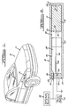
- an automotive vehicle 10 is illustrated as including a body indicated generally at 12 in which is mounted by appropriate means (not illustrated) an acceleration sensor 14.
- the sensor 14 is electrically connected as by wiring indicated at 16 to an electrical power supply 18 as indicated schematically in Fig. 2 and to an electrically operated occupant restraint system such as the inflatable restraint indicated at 20 in Fig. 2.
- the sensor 14 is illustrated as comprising a housing 22, an acceleration sensing mass 24 and a contact subassembly 26.
- the housing 22 is preferably formed as a glass tube having an axially extending bore 28 which terminates at a wall 30 closing one end.
- the acceleration sensing mass 24 is formed from a relatively dense material and may, for example, be fabricated as a powered metal part or an impact extrusion to facilitate manufacturing owing to its simple shape as illustrated in Fig. 2. It is formed as an elongated cylindrical member having its outer diameter sized to provide a predetermined clearance 31 within the bore 28. It is a symmetrically constructed part and the outer surface of each end is chamfered as indicated at 32, 34 to facilitate insertion into the bore 28, and centrally located recesses 36, 38 are provided at each end. Provision of the recess 38 at the end of the mass 24 which is abuttingly engageable with the wall 30 facilitates location and operation of the mass 24 by reducing the contact area with the wall 30. Provision of the recess 36 at the other end of the mass 24 provides a locating and retaining pocket for receiving a portion of the contact subassembly 26 as may readily be seen in Figs. 2 and 4.
- the contact subassembly 26 consists of a cylindrical plug 40, preferably formed as a glass part, a ring contact 42 and a columnar contact 44.
- the plug 40 is configured to engage mounting portions 46, 48 of the ring contact 42 and the columnar contact 44, respectively, in hermetically sealed fashion in a known manner.
- the plug in turn is sealed as indicated at 50 to the housing 22 adjacent its open end 52.
- the plug 40 therefore, closes the housing 22 to define a sensing chamber 54 within it.
- the ring contact 42 is a formed strip or blade member that may be fabricated from any suitable electrically conductive material having appropriate elasticity for performing the functions of the contacts 42, 44. Those skilled in the sensor design arts will appreciate that such materials may include alloys of copper which include beryllium, commonly referred to as “beryllium copper", and stainless steel of the 400 series as defined by the Society of Automotive Engineers.
- the ring contact 42 includes an elongated connecting strip 56 which joins the mounting portion 46 to a circumferentially extending contact plate 58. In the assembled position shown in Fig. 2, the contact plate 58 is positioned within the chamber 54 near the normal assembled position of the acceleration sensing mass 24.
- the columnar contact 44 includes a connecting portion 60 which extends from the mounting portion 48 to a turned-over contact portion 62.
- the connecting portion 60 is radially offset from the axes of the bore 28 and the sensing mass 24.
- assembly of the sensor 14 of the present invention may be accomplished rather simply utilizing well-known manufacturing techniques, such as have been employed in the production of light bulbs and vacuum tubes.
- the sensing mass 24 is first placed into the assembled position shown in Fig. 2 within the glass housing 22.
- the contact subassembly 26 is inserted to close the housing 22 and the plug 40 in the housing 22 may be laser fused into sealing engagement.
- this assembly and sealing process take place in an inert atmosphere so that the sensing chamber 54 can be filled with a dry inert gas, such as argon and nitrogen to eliminate corrosion and greatly lengthen the useful life of the sensor 14.
- a dry inert gas such as argon and nitrogen
- the sensor 14 is positioned in the body 12 of the vehicle 10 so that the closed end of the housing 22 faces the front of the vehicle at which location an impact may occur. It may be understood, however, that other sensors may be placed in the vehicle positioned to face other locations likely to sense impacts of the character that would activate the inflatable restraint 20.
- the sensing mass 24 In the installed position shown in Fig. 2, the sensing mass 24 abuttingly engages the wall 30 of the housing 22, resiliently urged into that position by the columnar contact 44. Upon the occurrence of an impact resulting in an acceleration pulse of a predetermined magnitude and duration, the sensing mass 24 slides along the bore 28 and collapses the columnar contact 44, bowing it outwardly in the direction of its radial offset to engage the contact plate 58 while the contact portion 62 is retained within the outer wall of the sensing mass recess 36, as is illustrated in Fig. 4. This completes the electrical circuit between power supply 18 and the inflatable restraint 20 to activate the passive occupant restraint system of the vehicle 10.
- the cross-section and the length of the columnar contact 44 are chosen to provide a threshold resistance to movement by the mass 24 preventing inadvertent actuation of the inflatable restraint 20 in response to acceleration pulses below a predetermined magnitude.
- the cross-section and length of the contact 42 and the mass and radial clearance of the acceleration sensing mass 24 with respect to the housing bore 28 may be chosen to produce an actuation response characteristic for the sensor 14 which is appropriate for operating the inflatable restraint 20 of the vehicle 10 rapidly while preventing inadvertent actuations.
Landscapes
- Switches Operated By Changes In Physical Conditions (AREA)
- Air Bags (AREA)
Claims (6)
- Détecteur d'accélération destiné à transmettre un signal électrique lors de l'occurence d'une impulsion d'accélération de magnitude et de durée prédéterminées, ledit détecteur comprenant
un boîtier (22),
une masse de détection (24) montée dans le boîtier (22) pouvant effectuer un mouvement coulissant amorti le long d'un axe du boîtier, et
un élément de contact électrique fixe (42) transporté avec le boîtier,
caractérisé par
un élément de contact électrique pouvant être déféchi (44) dont une extrémité est transportée de manière rigide avec le boîtier (22) et ayant une portion de contact (62) s'engageant de manière résiliente avec la masse de détection (24) de manière colonnaire afin d'incliner la masse (24) dans une direction par rapport au boîtier (22), la masse de détection (24) se déplaçant lors de l'occurence d'une impulsion d'accélération de magnitude et de durée prédéterminées pour infléchir l'élément de contact pouvant être défléchi (44), réduisant la force d'inclinaison de celui-ci proportionnellement au mouvement et amenant les portions de contact (62) de l'élément de contact pouvant être défléchi (44) à s'engager avec l'élément de contact électrique fixe (42), transmettant de ce fait le signal électrique. - Détecteur d'accélération selon la revendication 1, destiné à transmettre un signal électrique depuis une source d'énergie jusqu'à un système de retenue du passager gonflable d'un véhicule lors de l'occurence d'une impulsion d'accélération de magnitude et de durée prédéterminées, dans lequel le boîtier est un boîtier allongé (22) destiné à être monté dans le véhicule et présente un alésage (28) s'étendant de manière axiale depuis une extrémité ouverte (52) du boîtier et se terminant à une extrémité fermée, le boîtier ayant une prise (40) engagée de manière scellée avec le boîtier afin de fermer l'extrémité ouverte du boîtier et par là définir une chambre de détection fermée, où ladite masse de détection (24) est reçue de manière coulissante dans l'alésage (28) et présente une surface externe cylindrique dont les dimensions définissent un jeu diamétral prédéterminé (31) avec l'alésage (28), où l'élément de contact pouvant être défléchi (44) est formé à partir d'une matière électroconductrice comme un élément de lame résiliente transporté de manière hermétique par la prise (40) et s'étendant à travers celle-ci et dont la portion de contact (62) s'engage de manière attenante avec la masse de détection (24) afin de pousser la masse de détection (24) vers l'extrémité fermée du boîtier et une portion de colonne de connection (60) s'étendant entre la portion de contact (62) et la prise (40), et où l'élément de contact fixe est un élément de contact annulaire (42) formé à partir d'une matière électroconductrice, transporté de manière hermétique par la prise (40) et s'étendant à travers celle-ci et présentant une plaque de contact s'étendant de manière circulaire (58) placée dans l'alésage (28) en concordance axiale avec une portion de la portion de colonne de connection et espacée de celle-ci de manière radiale, l'élément de contact (44)- et l'élément de contact annulaire (42) définissant un commutateur normalement ouvert pouvant être relié entre la source d'énergie et le système de retenue gonflable du passager, et dans lequel lors de l'occurence d'une impulsion d'accélération prédéterminée, la masse de détection (24) s'éloigne de l'extrémité fermée du boîtier de manière coulissante , défléchissant la portion de colonne (60) qui s'engage avec la plaque de contact (58) de manière à transmettre le signal électrique depuis la source d'énergie jusqu'au système de retenue gonglable du passager.
- Détecteur selon la revendication 2, dans lequel la chambre de détection (22) est remplie de gaz inerte sec.
- Détecteur selon la revendication 2, dans lequel l'élément de contact pouvant être défléchi (44) et l'élément de contact annulaire (42) sont fabriqués à partir de cuivre de béryllium ou d'acier inoxydable.
- Détecteur selon la revendication 2, dans lequel la portion de colonne de connection (60) fait radialement saillie de la portion de contact (62).
- Détecteur selon la revendication 1, dans lequel la masse de détection (24) comprend un élément cylindrique ayant un évidement central formé sur au moins une extrémité destinée à recevoir la portion de contact (62).
Applications Claiming Priority (2)
| Application Number | Priority Date | Filing Date | Title |
|---|---|---|---|
| US07/288,382 US4857680A (en) | 1988-12-22 | 1988-12-22 | Acceleration sensor |
| US288382 | 1988-12-22 |
Publications (2)
| Publication Number | Publication Date |
|---|---|
| EP0375154A1 EP0375154A1 (fr) | 1990-06-27 |
| EP0375154B1 true EP0375154B1 (fr) | 1994-08-24 |
Family
ID=23106865
Family Applications (1)
| Application Number | Title | Priority Date | Filing Date |
|---|---|---|---|
| EP89311939A Expired - Lifetime EP0375154B1 (fr) | 1988-12-22 | 1989-11-17 | Capteur d'accélération |
Country Status (3)
| Country | Link |
|---|---|
| US (1) | US4857680A (fr) |
| EP (1) | EP0375154B1 (fr) |
| DE (1) | DE68917700T2 (fr) |
Families Citing this family (9)
| Publication number | Priority date | Publication date | Assignee | Title |
|---|---|---|---|---|
| US5005861A (en) * | 1989-10-19 | 1991-04-09 | Breed Automotive Technology, Inc. | Velocity change sensor with double pole sensor |
| SE513091C2 (sv) * | 1989-10-06 | 2000-07-03 | Breed Automotive Tech | Accelerometer för avkänning av hastighetsförändringar hos ett fordon |
| US5322325A (en) * | 1989-10-19 | 1994-06-21 | Breed Automotive Technology, Inc. | Safing velocity change sensor |
| US5098122A (en) * | 1989-12-06 | 1992-03-24 | Breed Automotive | Velocity change sensor with improved spring bias |
| US5153393A (en) * | 1990-03-22 | 1992-10-06 | David S. Breed | Crash sensor for a passive motor vehicle occupant restraint system |
| US5608270A (en) * | 1990-11-19 | 1997-03-04 | Meister; Jack B. | Vehicle safety restraint system with linear output impact sensor |
| US5332876A (en) * | 1993-05-06 | 1994-07-26 | Comus International | Electrical tilt switch employing multiple conductive spheres |
| US20090132129A1 (en) * | 1993-09-16 | 2009-05-21 | Automotive Technologies International, Inc. | Side Impact Sensor Systems |
| US6313418B1 (en) | 1996-01-12 | 2001-11-06 | Breed Automotive Technology, Inc. | Glass encapsulated extended dwell shock sensor |
Family Cites Families (17)
| Publication number | Priority date | Publication date | Assignee | Title |
|---|---|---|---|---|
| US2458479A (en) * | 1943-04-28 | 1949-01-04 | Thomas M Perry | Setback switch |
| DE918577C (de) * | 1951-04-29 | 1954-09-30 | Standard Elek Zitaets Ges Ag | Schalter |
| US2930863A (en) * | 1958-07-21 | 1960-03-29 | Raymond L Renner | Acceleration detectors |
| US3156794A (en) * | 1962-12-26 | 1964-11-10 | Honeywell Inc | Omni-directional impact switch |
| US3484571A (en) * | 1968-03-15 | 1969-12-16 | Us Navy | Inertia switch |
| US3571539A (en) * | 1968-08-20 | 1971-03-23 | Eaton Yale & Towne | Collision sensor |
| US3688063A (en) * | 1971-02-22 | 1972-08-29 | Technar Inc | Crash sensing switch |
| US3753475A (en) * | 1971-11-15 | 1973-08-21 | F Povilaitus | Passenger safety restraint device including bumper mounted switch and associated circuitry |
| US3836738A (en) * | 1973-04-13 | 1974-09-17 | R Baland | Impact switch with inertia operated toggle linkage actuator mechanism |
| CH571417A5 (en) * | 1973-11-26 | 1976-01-15 | Budmiger Hermann | Hazard warning light for motor vehicles - circuit completed by inertia or manual switch |
| JPS573178B2 (fr) * | 1974-02-26 | 1982-01-20 | ||
| US3974350A (en) * | 1974-07-24 | 1976-08-10 | Breed Corporation | Gas damped vehicular crash sensor with gas being dominant biasing force on sensor |
| DE2547257C3 (de) * | 1975-10-22 | 1978-04-27 | 5060 Bergisch Gladbach | Elektrischer Schaltkontakt mit extrem kleinem Betätigungsweg |
| US4097699A (en) * | 1976-09-07 | 1978-06-27 | Eaton Corporation | Viscous damped crash sensor unit with inertia switch |
| US4116132A (en) * | 1976-12-17 | 1978-09-26 | Technar Incorporated | Inertial sensors |
| US4329549A (en) * | 1980-04-29 | 1982-05-11 | Breed Corporation | Magnetically biased velocity change sensor |
| US4536629A (en) * | 1983-11-03 | 1985-08-20 | Technar, Incorporated | Gas damped acceleration switch |
-
1988
- 1988-12-22 US US07/288,382 patent/US4857680A/en not_active Expired - Fee Related
-
1989
- 1989-11-17 EP EP89311939A patent/EP0375154B1/fr not_active Expired - Lifetime
- 1989-11-17 DE DE68917700T patent/DE68917700T2/de not_active Expired - Fee Related
Also Published As
| Publication number | Publication date |
|---|---|
| DE68917700D1 (de) | 1994-09-29 |
| US4857680A (en) | 1989-08-15 |
| DE68917700T2 (de) | 1994-12-22 |
| EP0375154A1 (fr) | 1990-06-27 |
Similar Documents
| Publication | Publication Date | Title |
|---|---|---|
| US4329549A (en) | Magnetically biased velocity change sensor | |
| US4900880A (en) | Gas damped crash sensor | |
| US4284863A (en) | Velocity change sensor | |
| US3974350A (en) | Gas damped vehicular crash sensor with gas being dominant biasing force on sensor | |
| US5231253A (en) | Side impact sensors | |
| US3889130A (en) | Mass in liquid vehicular crash sensor | |
| US4877927A (en) | Extended dwell shock sensing device | |
| EP0323022B1 (fr) | Détecteur d'accélération à amortissement par fluide | |
| US5192838A (en) | Frontal impact crush zone crash sensors | |
| US4857680A (en) | Acceleration sensor | |
| CA2012997A1 (fr) | Methode et dispositif d'essai de detecteurs d'impacts accelerometriques | |
| US3485973A (en) | Switch mechanism | |
| US3571539A (en) | Collision sensor | |
| US5756948A (en) | Side-impact electro-mechanical accelerometer to actuate a vehicular safety device | |
| GB2252206A (en) | Crash sensor | |
| CA2027927C (fr) | Accelerometre avec ressort de positionnement | |
| US5440084A (en) | Shock detecting system | |
| US5011182A (en) | Velocity change sensor with contact retainer | |
| US4929805A (en) | Gas damped deceleration switch | |
| US5845730A (en) | Electro-mechanical accelerometer to actuate a vehicular safety device | |
| CA2071073C (fr) | Capteur de variation de vitesse muni d'un aimant cylindrique | |
| US5178410A (en) | Velocity change sensor with lateral shock absorber | |
| WO1990010302A1 (fr) | Detecteurs d'impact pour vehicules automobiles, utilises avec des systemes de securite automatiques | |
| US3655928A (en) | Device for detecting and signaling a change of more than a prescribed amount in the rate of movement of an object | |
| JP3175557B2 (ja) | 双方向作動型衝撃センサ |
Legal Events
| Date | Code | Title | Description |
|---|---|---|---|
| PUAI | Public reference made under article 153(3) epc to a published international application that has entered the european phase |
Free format text: ORIGINAL CODE: 0009012 |
|
| AK | Designated contracting states |
Kind code of ref document: A1 Designated state(s): DE FR GB |
|
| 17P | Request for examination filed |
Effective date: 19901027 |
|
| 17Q | First examination report despatched |
Effective date: 19930217 |
|
| GRAA | (expected) grant |
Free format text: ORIGINAL CODE: 0009210 |
|
| AK | Designated contracting states |
Kind code of ref document: B1 Designated state(s): DE FR GB |
|
| ET | Fr: translation filed | ||
| REF | Corresponds to: |
Ref document number: 68917700 Country of ref document: DE Date of ref document: 19940929 |
|
| PLBE | No opposition filed within time limit |
Free format text: ORIGINAL CODE: 0009261 |
|
| STAA | Information on the status of an ep patent application or granted ep patent |
Free format text: STATUS: NO OPPOSITION FILED WITHIN TIME LIMIT |
|
| 26N | No opposition filed | ||
| PGFP | Annual fee paid to national office [announced via postgrant information from national office to epo] |
Ref country code: DE Payment date: 19971021 Year of fee payment: 9 |
|
| PGFP | Annual fee paid to national office [announced via postgrant information from national office to epo] |
Ref country code: GB Payment date: 19971031 Year of fee payment: 9 |
|
| PGFP | Annual fee paid to national office [announced via postgrant information from national office to epo] |
Ref country code: FR Payment date: 19971105 Year of fee payment: 9 |
|
| REG | Reference to a national code |
Ref country code: GB Ref legal event code: 746 Effective date: 19971023 |
|
| REG | Reference to a national code |
Ref country code: FR Ref legal event code: D6 |
|
| PG25 | Lapsed in a contracting state [announced via postgrant information from national office to epo] |
Ref country code: GB Free format text: LAPSE BECAUSE OF NON-PAYMENT OF DUE FEES Effective date: 19981117 |
|
| GBPC | Gb: european patent ceased through non-payment of renewal fee |
Effective date: 19981117 |
|
| PG25 | Lapsed in a contracting state [announced via postgrant information from national office to epo] |
Ref country code: FR Free format text: LAPSE BECAUSE OF NON-PAYMENT OF DUE FEES Effective date: 19990730 |
|
| REG | Reference to a national code |
Ref country code: FR Ref legal event code: ST |
|
| PG25 | Lapsed in a contracting state [announced via postgrant information from national office to epo] |
Ref country code: DE Free format text: LAPSE BECAUSE OF NON-PAYMENT OF DUE FEES Effective date: 19990901 |