EP0375228B1 - Moteur commuté électroniquement et induit fixe pour celui-ci avec des dents présentant des rainures et un angle entre les encoches et le champ des aimants permanents afin de réduire la pulsation du couple - Google Patents
Moteur commuté électroniquement et induit fixe pour celui-ci avec des dents présentant des rainures et un angle entre les encoches et le champ des aimants permanents afin de réduire la pulsation du couple Download PDFInfo
- Publication number
- EP0375228B1 EP0375228B1 EP89312870A EP89312870A EP0375228B1 EP 0375228 B1 EP0375228 B1 EP 0375228B1 EP 89312870 A EP89312870 A EP 89312870A EP 89312870 A EP89312870 A EP 89312870A EP 0375228 B1 EP0375228 B1 EP 0375228B1
- Authority
- EP
- European Patent Office
- Prior art keywords
- motor
- notches
- tooth
- rotatable assembly
- tip
- Prior art date
- Legal status (The legal status is an assumption and is not a legal conclusion. Google has not performed a legal analysis and makes no representation as to the accuracy of the status listed.)
- Expired - Lifetime
Links
- 230000005291 magnetic effect Effects 0.000 claims description 58
- 238000004804 winding Methods 0.000 claims description 40
- 230000004907 flux Effects 0.000 claims description 6
- 230000010287 polarization Effects 0.000 claims description 5
- 230000008878 coupling Effects 0.000 claims description 3
- 238000010168 coupling process Methods 0.000 claims description 3
- 238000005859 coupling reaction Methods 0.000 claims description 3
- 230000004044 response Effects 0.000 claims description 2
- 238000006073 displacement reaction Methods 0.000 description 21
- 230000007704 transition Effects 0.000 description 14
- 238000003475 lamination Methods 0.000 description 12
- 230000003247 decreasing effect Effects 0.000 description 3
- 230000000694 effects Effects 0.000 description 3
- 230000000712 assembly Effects 0.000 description 1
- 238000000429 assembly Methods 0.000 description 1
- 230000004323 axial length Effects 0.000 description 1
- 238000010276 construction Methods 0.000 description 1
- 230000007423 decrease Effects 0.000 description 1
- 230000005672 electromagnetic field Effects 0.000 description 1
- 230000008030 elimination Effects 0.000 description 1
- 238000003379 elimination reaction Methods 0.000 description 1
- 238000005086 pumping Methods 0.000 description 1
- 230000009467 reduction Effects 0.000 description 1
- 229920006395 saturated elastomer Polymers 0.000 description 1
- 230000002123 temporal effect Effects 0.000 description 1
- 238000003466 welding Methods 0.000 description 1
Images



Classifications
-
- H—ELECTRICITY
- H02—GENERATION; CONVERSION OR DISTRIBUTION OF ELECTRIC POWER
- H02K—DYNAMO-ELECTRIC MACHINES
- H02K1/00—Details of the magnetic circuit
- H02K1/06—Details of the magnetic circuit characterised by the shape, form or construction
- H02K1/22—Rotating parts of the magnetic circuit
- H02K1/27—Rotor cores with permanent magnets
- H02K1/2706—Inner rotors
- H02K1/272—Inner rotors the magnetisation axis of the magnets being perpendicular to the rotor axis
- H02K1/274—Inner rotors the magnetisation axis of the magnets being perpendicular to the rotor axis the rotor consisting of two or more circumferentially positioned magnets
- H02K1/2753—Inner rotors the magnetisation axis of the magnets being perpendicular to the rotor axis the rotor consisting of two or more circumferentially positioned magnets the rotor consisting of magnets or groups of magnets arranged with alternating polarity
- H02K1/278—Surface mounted magnets; Inset magnets
-
- H—ELECTRICITY
- H02—GENERATION; CONVERSION OR DISTRIBUTION OF ELECTRIC POWER
- H02K—DYNAMO-ELECTRIC MACHINES
- H02K1/00—Details of the magnetic circuit
- H02K1/06—Details of the magnetic circuit characterised by the shape, form or construction
- H02K1/12—Stationary parts of the magnetic circuit
- H02K1/16—Stator cores with slots for windings
-
- H—ELECTRICITY
- H02—GENERATION; CONVERSION OR DISTRIBUTION OF ELECTRIC POWER
- H02K—DYNAMO-ELECTRIC MACHINES
- H02K1/00—Details of the magnetic circuit
- H02K1/06—Details of the magnetic circuit characterised by the shape, form or construction
- H02K1/22—Rotating parts of the magnetic circuit
- H02K1/27—Rotor cores with permanent magnets
- H02K1/2786—Outer rotors
- H02K1/2787—Outer rotors the magnetisation axis of the magnets being perpendicular to the rotor axis
- H02K1/2789—Outer rotors the magnetisation axis of the magnets being perpendicular to the rotor axis the rotor consisting of two or more circumferentially positioned magnets
- H02K1/2791—Surface mounted magnets; Inset magnets
-
- H—ELECTRICITY
- H02—GENERATION; CONVERSION OR DISTRIBUTION OF ELECTRIC POWER
- H02K—DYNAMO-ELECTRIC MACHINES
- H02K29/00—Motors or generators having non-mechanical commutating devices, e.g. discharge tubes or semiconductor devices
- H02K29/06—Motors or generators having non-mechanical commutating devices, e.g. discharge tubes or semiconductor devices with position sensing devices
- H02K29/12—Motors or generators having non-mechanical commutating devices, e.g. discharge tubes or semiconductor devices with position sensing devices using detecting coils using the machine windings as detecting coil
-
- H—ELECTRICITY
- H02—GENERATION; CONVERSION OR DISTRIBUTION OF ELECTRIC POWER
- H02K—DYNAMO-ELECTRIC MACHINES
- H02K2201/00—Specific aspects not provided for in the other groups of this subclass relating to the magnetic circuits
- H02K2201/06—Magnetic cores, or permanent magnets characterised by their skew
Definitions
- This invention relates to dynamoelectric machines and in particular to an electronically commutated motor having a rotatable assembly having skewed magnetics for reducing cogging and having a stationary assembly with notched teeth to reduce cogging.
- While conventional brush-commutated DC motors may have advantageous characteristics, including convenience of changing operational speeds, there may be disadvantages such as cogging, brush wear, electrical loss, noise and radio frequency interference caused by sparking between the brushes and the segmented commutator, which may limit the applicability of such brush-commutated DC motors in some fields such as the furnace blower control field.
- Electronically commutated motors such as brushless DC motors and permanent magnet motors with electronic commutation, have now been developed and generally are believed to have advantageous characteristics over brush commutated DC motors without many of the disadvantages thereof while also having other important advantages.
- Such brushless DC motors have a stator with a plurality of windings therein, a rotor with a plurality of constant magnetic polar regions providing variable air gap energy, and sensors for sensing the relative position of the rotor polar regions with respect to the stator. Signals developed by the position sensors were processed by circuitry for selectively energizing the windings of the motor.
- JP-A-56-153961 discloses a rotary electric machine, which is designed to reduce the cogging force and to equalize the electromagnetic torque of the machine by forming auxiliary grooves on the main and the auxiliary salient poles of an armature core and providing skews on the respective magnet poles.
- the machine comprises an annular magnet mounted on a rotor which has N poles, S poles and nonmagnetic poles, each of which has equal angular width.
- An armature core 3 has main salient poles of 60° effective pitch and auxiliary salient poles of 30° effective pitch, and auxiliary grooves each having a pitch (15° interval) of 1/4 of the effective pitch of the main salient pole are provided at the part which is effectively confronted with the main and the auxiliary salient poles. Skews each having a skew angle corresponding to the pitch of the auxiliary groove are formed at the respective poles of the magnet.
- an electronically commutated motor comprising a rotatable assembly having a plurality of permanent magnet areas which rotate about an axis of rotation as the rotatable assembly rotates and a stationary assembly in magnetic coupling relation with the permanent magnet areas of the rotatable assembly, characterized in that the permanent magnet areas are orientated with respect to the axis of rotation to provide a magnetic field with lines of flux along a plane forming a skew angle of s mechanical degrees with respect to the axis of rotation, wherein s is not equal to zero, each of the permanent magnet areas comprising at least two circumferentially adjacent permanently magnetized magnetic segments having radial polarization and having a space between segments comprising an axially elongate substantially unmagnetized portion forming a skew angle of s i mechanical degrees with respect to the axis of rotation; and the stationary assembly having t spaced teeth with adjacent teeth defining a slot therebetween, each tooth having winding stages with respect to the teeth adapted for
- High quality servo motors must operate with precision at zero speed. In order to achieve such precision, a servo motor should have essentially no cogging effects such as experienced with a surface mounted magnet, electronically commutated motor. The essential elimination of the cogging effects must be accomplished without adding complexity to the servo control. Cogging in an electronically commutated motor can be substantially eliminated by skewing either the magnetic field of the rotatable assembly by one slot pitch or by skewing the stator laminations by one slot pitch. This skewing must be accomplished without reducing the width (duration) of the "flat top" of the back electromotive force (EMF) waveform. The effect of a flat top of reduced width is an undesirable torque dip whenever a commutation occurs.
- EMF back electromotive force
- a notch in the face of a tooth to "fake" a slot opening reduces the skew angle required to reduce cogging by one-half. This significantly improves the duration of the flat top of the back EMF waveform. Further reduction in the skew angle required to reduce cogging can be achieved by employing two or more notches in the tooth face. If two notches are employed in the tooth face, the skew required is reduced to one-third of the skew required when no notches are employed. In this configuration, the flat top duration will very nearly be at the desired value.
- the motor 10 includes a rotatable assembly 100 having three permanent magnet elements 102 which rotate about an axis 104 of rotation as the rotatable assembly rotates.
- the motor also includes a stationary assembly 106 in magnetic coupling relation with the permanent magnet elements 102 of the rotatable assembly 100.
- Stationary assembly 106 has t spaced teeth 108 with adjacent teeth defining a slot 110 therebetween.
- the stationary assembly 106 has distributed winding stages 107 on three adjacent teeth 108 adapted for commutation in at least one preselected sequence. As illustrated, three windings may be used, each winding being around three adjacent teeth and being indicated by a square, circle or triangle.
- the motor 10 is shown in a standard configuration with the rotatable assembly 100 within stationary assembly 106, it is contemplated that the invention may be used on an inside-out motor wherein the stationary assembly 106 is within the rotatable assembly.
- a motor with nine (9) teeth 108 is shown so that the number of teeth (t) equals 9.
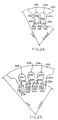
- a 180 frame lamination 202 with an inner diameter of 58.72 mm (2.312 inches) and an outer diameter of 95 mm (3.74 inches) and having 36 teeth 204 is shown so that t equals 36. Only a portion of the lamination is illustrated. Adjacent teeth 204 define a slot 206 therebetween. Each tooth 204 has a single notch 208 therein so that n equals 1. Each tooth 204 has surfaces 210,212 which would face the rotatable assembly. As illustrated in Figure 2B, a 180 frame lamination 222 with 24 teeth 224 is shown so that t equals 24. Only a portion of the lamination is illustrated. Adjacent teeth 224 define a slot 226 therebetween. Each tooth 224 has two notches 228 therein so that n equals 2. Each tooth 224 has surfaces 230, 232, 234 which would face the rotatable assembly.
- the stationary assembly 106 comprises a plurality of winding stages adapted to be electrically energized to generate an electromagnetic field.
- the stages are coils of wire individually wound around a tooth of the laminated stator core.
- the core is formed from a stack of laminations as illustrated, forexample, in Figures 2Aand 2B and may be held together by four retainer clips, one positioned within each corner of the core.
- the core may be held together by other suitable means, such as for instance welding or adhesively bonding, or merely held together by the windings, all as will be understood by those skilled in the art. While stationary assembly is illustrated for purposes of disclosure, it is contemplated that other stationary assemblies of various other constructions having different shapes and with different number of teeth may be utilized within the scope of the invention so as to meet at least some of the objects thereof.
- FIG 3 is an enlarged perspective illustration of the teeth 224 of the lamination of Figure 2B.
- Each notch 302 has a length L measured along the elongate dimension of the notch, a transverse width W measured along an axis transverse and perpendicular to the elongate axis and parallel to surface 312, 314, 316.
- the notch 302 also has a radial depth D measured along the radius of the axis of axis 104 of rotation (shown in Figure 1).
- the notch is illustrated as substantially rectangular in cross-section, it is recognized that the notch may be any shape or cross-section such as semi-circular as shown in Figure 2A.
- the motor assembly operates in the following manner.
- three sets of magnetic poles are established that will provide a radial magnetic field which moves clockwise or counterclockwise around the core depending on the preselected sequence or order in which the stages are energized.
- This moving field intersects with the flux field of the magnet poles to cause the rotor to rotate relative to the core in the desired direction to develop a torque which is a direct function of the intensities or strengths of the magnetic fields.
- the winding stages are commutated without brushes by sensing the rotational position of the rotatable assembly as it rotates within the core and utilizing electrical signals generated as a function of the rotational position of the rotor sequentially to apply a DC voltage to each of the winding stages in different preselected orders or sequences that determine the direction of the rotation of the rotor.
- Position sensing may be accomplished by a position-detecting circuit responsive to the back electromotive force (EMF) to provide a simulated signal indicative of the rotational position of the rotor to control the timed sequential application of voltage to the winding stages of the motor.
- EMF back electromotive force
- motor 10 may also include means (not shown), such as a printed circuit board, for sensing the back electromotive (EMF) force induced in each of the winding stages by permanent magnet elements 102.
- the printed circuit board commutates the winding stages in response to the sensing of the back emf induced in the winding stages to rotate rotatable assembly 100.
- the skewed notches 118 reduce cogging between the rotatable assembly and the stationary assembly as the rotatable assembly rotates by distributing the magnetic flux so that a substantially constant air gap energy is provided.
- Other means for position sensing may also be used.
- each tooth 224 may be provided with a laterally transversely extending tip 320 integral with the tooth.
- Tip 320 forms part of the surface 312, 314, 316 which is adjacent the rotatable assembly.
- Reference character 322 generally marks the boundary between tooth 224 and tip 320.
- Notch 302 is positioned to be centered at this boundary 322 of tip 318 and tooth 224 so that a portion 324 of the notch 302 is in the tooth 224 and the remaining portion 326 of the notch 302 in the tip 318.
- notch 302 has opposite sides 328 and 330 which are parallel to each other and a bottom surface.
- the portion 324 of the bottom surface which is part of and within tooth 224 is substantially parallel to surfaces 312,314 which face the rotatable assembly.
- the remaining portion 326 of the bottom surface which is part of and within tip 318 is substantially parallel to the surface of tip 318 opposite surface 312, 314, i.e., base surface 336 of tip 318.
- the total mass of tip 318 is increased as compared to a notch having a substantially rectangular cross section with a bottom surface which is substantially planar and parallel to surfaces 312, 314.
- the mass of the tip 318 may be increased by altering its shape.
- the axial length L A of the tip may be increased such as by flairing the edges 515 of the tip axially in order to increase the mass of the tip as shown in Figure 5.
- All dimensions are approximate and the dimensions referred to herein are the average dimension of the notch in each indicated direction.
- the notch may be unsymmetrical. Where a dimension of a notch is not the same throughout the entire notch, the average dimension in each indicated direction would be considered the width, depth and length of the notch.
- the entire notch 118 may be located within tip 120 (notshown).
- the bottom surface of the tip has a surface substantially parallel to the surface of the tip which is opposite the surface of the tip adjacent to rotatable assembly 100.
- Each notch 502,504 is along a helical path 504 which traverses a skew angle of s mechanical degrees with respect to the axis 104 of rotation wherein S is not equal to zero.
- this path is helical although it is illustrated as a straight line because surface 512, 514, 516 has a generally cylindrical shape as does the outer surface of elements 102 of the rotatable assembly 100 of Figure 1.
- Slot 520 is also skewed at a skew angle of s mechanical degrees with respect to the axis of rotation. As a result, the two notches 502 are substantially parallel to the slot 520.
- FIGS 6A, 6B and 6C illustrate in plan view various variations of the invention wherein a face has a notched tooth. It has been found that substantially constant air gap energy can be maintained and thereby cogging is substantially eliminated.
- notches 602 and 604 in the surface of the tooth which is adjacent the rotatable assembly define lands 606,608 and 610. From a plan perspective view, both the notches and the lands have a rectangular shape. Both notches 602 and 604 have the same shape, i.e., width W measured transverse to the axis of rotation 612 and length L measured along the axis of rotation 612.
- the n notches in the surface of each tooth define n+1 lands.
- Each land has a surface area substantially equal to the width W times the length L of each notch, i.e., the area of the bottom of each notch is substantially equal to the area of each land.
- neither the notches nor the slots between the teeth and defined by edges 614, 616 are skewed so that the elongate axis of both the notches and the slots are parallel to the axis of rotation represented by line 612.
- Both the notches and the lands have the same plan shape.
- the rotor magnetics would be skewed as indicated below.
- notches 622 and 624 in the surface of the tooth which is adjacent the rotatable assembly define lands 626, 628 and 630. From a plan perspective view, both the notches and the lands are in the shape of a parallelogram. Both notches 622 and 624 have the same shape, i.e., width W measured transverse to the axis of rotation 632 and length L measured along the axis of rotation 632.
- the n notches in the surface of each tooth define n+1 lands. Each land has a surface area substantially equal to the width W times the length L of each notch, i.e., the area of the bottom of each notch is substantially equal to the area of each land.
- both the notches and the slots between the teeth and defined by edges 634, 636 are skewed by s mechanical degrees with respect to the axis of rotation so that the elongate axis of both the notches and the slots form an angle s with the axis of rotation represented by line 632.
- Both the notches and the lands have the same plan shape.
- the rotor magnetics may be skewed as indicated below.
- notches 652 and 654 in the surface of the tooth which is adjacent the rotatable assembly define lands 656, 658 and 660.
- the notches are in the shape of a parallelogram
- land 658 is in the shape of a parallelogram
- lands 656, 660 are in the shape of a trapezoid.
- Both notches 652 and 654 have the same shape, i.e., width W measured transverse to the axis of rotation 662 and length L measured along the axis of rotation 662.
- the n notches in the surface of each tooth define n+1 lands.
- Each land has a surface area substantially equal to the width W times the length L, of each notch, i.e., the area of the bottom of each notch is substantially equal to the area of each land.
- the notches are skewed whereas the slots formed by edges 664, 666 are parallel to the axis of rotation 662 so that the elongate axis of the notches forms an angle s with the axis of rotation represented by line 612 and the lands are parallel to the axis of rotation.
- the lands and notches have different plan shapes.
- the rotor magnetics may be skewed as indicated below.
- the motor of the invention has a rotatable assembly with p poles and a stationary assembly with 3p teeth and with distributed windings, each winding on three teeth, it has been found that substantially constant air gap energy can be maintained while providing back EMF signal having a maximized flat top width of 120° electrical.
- Figure 7 is a table of the operating parameters of various motors. In general, the larger the skew angle, the smaller the flat top duration.
- the flat top duration decreases.
- a skew of zero degrees yields a flat top having a duration (width) of 144 electrical degrees.
- Increasing the skew angle to 5° yields a decreased flat top width of 124°.
- Increasing the skew angle to 7.5° yields a decreased flat top width of 114°.
- Increasing the skew angle to 15° yields a decreased flat top width of 84°. Therefore, optimum motor performance is achieved by minimizing cogging and maintaining the flat top width at about 120° electrical.
- the skew angle which results in this optimum motor performance for each configuration illustrated in Figure 7 is indicated in the column for 360/(n+1)t and corresponds to the flat top duration which has been underlined for each configuration. For example, in the first configuration of Figure 7, optimum motor performance occurs with a 5° skew which provides a flat top duration of 118°. In the last configuration of Figure 7, optimum motor performance occurs with a 10° skew which provides a flat top duration of 124°.
- each tooth which is adjacent rotatable assembly 100 has a number of lands which is equal to n + 1 where n is the number of notches within the tooth.
- the tooth illustrated in Figure 3 has three lands. Cogging is substantially reduced and the duration of the flat top of the back emf is maintained when the area of each of the lands 112, 114, 116 is substantially equal to the area of the bottom surface of each notch, i.e., area of land approximately equals W x L.
- each notch should have a substantially rectangular cross-sectional shape as viewed in a transverse section.
- the transitions 802, 804 between the north permanent magnet pole 808 and the south permanent magnet pole 810 are oriented obliquely with respect to the axis of rotation 806 to provide a magnetic field with lines of flux along a plane forming a skew angle of s mechanical degrees with respect to the axis of rotation 806, where the skew angle s is not equal to zero.
- the scale 850 from zero to 360 indicates mechanical agrees about the periphery of the motor of Figure 8A. Stages A,B,C are separated by 10° slots 852.
- Figure 8A shows a salient pole motor, skewed rotor magnetics may also be part of a distributed winding motor.
- each of permanent magnet elements may be provided with a phantom magnet skew in the form of an axially elongate, substantially unmagnetized portion 812, 814 having a width of about four mechanical degrees (4°).
- the phantom skew forms a skew angle of s mechanical degrees with respect to axis 806.
- each of both the north permanent magnet element 808 and the south permanent magnet element 810 may comprise two permanently magnetized segments 816 and 818, 820 and 822, respectively, having the same polarization and having a space 824, 826 therebetween which is oblique to axis 806.
- Each space 824, 826 is an axially elongate opening forming a skew angle of s mechanical degrees with respect to the axis of rotation and is also referred to as a phantom magnet skew.
- this phantom magnet skew is at an angle which substantially equals 360° divided by 4(n+1)t.
- Phantom magnet skew may also be employed as part of a distributed winding motor.
- phantom magnet skews are part of rotatable assembly 100, it is generally unnecessary to also employ skewed notches although it is contemplated that both the notches and the spaces may be skewed. If skewed notches at a skew angle of s1 mechanical degrees and phantom magnetic skews are employed together in one motor configuration, the total skew s t , which is equal to the sum of s1 and s2 must substantially equal the optimum skew angle as noted above. Table 1 summarizes the optimum total skew required.
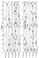
- Figures 9G, 9H, 91, 9J, and 9K are in vertical alignment with each other and illustrate the total optimum skew for a six-tooth motor with each tooth having two notches therein. Only three stages A, B, C are illustrated.
- Figures 9C, 9E, 91 and 9K correspond to salient pole motors having six teeth and four poles. Only half of such a salient motor is depicted, i.e., three teeth and two poles; the other half would have the same configuration as the illustrated portion.
- Figures 9D, 9F, 9H and 9J correspond to a distributed wound motor having six teeth and two poles. Only half of such a distributed wound motor is depicted, i.e., three teeth and one pole; the other half would have a configuration symmetrical to the illustration with opposite poles. Table 2 summarizes the features illustrated by each of these figures and the optimum total skew required.
- the optimum total skew equals the skew of the notches plus the skew of the rotor magnetics.
- the optimum total skew would equal the skew of the notches as indicated in figures 9C and 9D.
- the number of notches per tooth n must be an even number. This is because an odd number of notches per tooth in a salient winding motor will not reduce the amount of skew required to substantially eliminate cogging.
- the stationary assembly has no notches therein and is a linear layout along 6 scale 900 from zero to 180 mechanical degrees.
- Figure 9C illustrates a linear layout of a portion of a rotatable assembly having two permanent magnet poles 902, 904 and having skewed rotor magnetics without phantom skews for the motor in which the stages A,B,C are salient windings.
- Figure 9C confirms that transition 906 would cause cogging at 30° displacements and transition 908 would cause cogging at 60° displacements, which is an integer multiple of 30° displacements.
- Figure 9C confirms that 360/2(n+1)t specifies that the minimum angle for skewed rotor magnetics required to substantially eliminate cogging and to provide the maximum back EMF flat top width in a salient pole motor having no phantom magnetic skew.
- Figure 9D illustrates a linear layout of a portion of a rotatable assembly having one permanent magnet pole 912 and having skewed rotor magnetics without phantom skews for the motor in which the stages A,B,C are distributed windings.
- Figure 9D confirms that transition 914 would cause cogging at 60° displacements.
- Figure 9D confirms that 360/(n+1)t specifies that the minimum angle for skewed rotor magnetics required to substantially eliminate cogging and to provide the maximum back EMF flat top width in a distributed pole motor having no phantom magnetic skew.
- Figure 9E illustrates a linear layout of a portion of a rotatable assembly having two permanent magnet poles 922, 924, each having skewed rotor magnetics with phantom skews 926, 930, respectively, for the motor in which the stages A,B,C are salient windings.
- Figure 9E confirms that phantom skew 926 would cause cogging at 15° displacements, transition 928 would cause cogging at 30° displacements, phantom skew 930 would cause cogging at 45° and transition 932 would cause cogging at 60° displacements, each of which is an integer multiple of 15° displacements. Therefore, Figure 9E confirms that 360/2(n+1)t specifies that the minimum angle for skewed rotor magnetics required to substantially eliminate cogging and to provide the maximum back EMF flat top width in a salient pole motor having phantom magnetic skews.
- Figure 9F illustrates a linear layout of a portion of a rotatable assembly having one permanent magnet pole 942 having skewed rotor magnetics with phantom skew 944 for the motor in which the stages A,B,C are distributed windings.
- Figure 9F confirms that phantom skew 944 will cause cogging at 30° displacements and transition 946 would cause cogging at 60° displacements, which is an integer multiple of 30° displacements.
- Figure 9F confirms that 360/2(n+1)t specifies that the minimum angle for skewed rotor magnetics required to substantially eliminate cogging and to provide the maximum back EMF flat top width in a distributed pole motor having phantom magnetic skews.
- the stationary assembly has two notches 947, 948 in each tooth and is a linear layout along a scale 900 from zero to 180 mechanical degrees.
- Figure 9H illustrates a linear layout of a portion of a rotatable assembly having two permanent magnet poles 952, 954 and having skewed rotor magnetics without phantom skews for the motor in which the stages A,B,C are salient windings.
- Figure 9H confirms that transition 956 would cause cogging at 10° and transition 958 would cause cogging at 20° displacements, which is an integer multiple of 20° displacements.
- Figure 9H confirms that 360/2(n+1)t specifies that the minimum angle for skewed rotor magnetics required to substantially eliminate cogging and to provide the maximum back EMF flat top width in a salient pole motor having no phantom magnetic skew.
- Figure 91 illustrates a linear layout of a portion of a rotatable assembly having one permanent magnet pole 962 and having skewed rotor magnetics without phantom skews for the motor in which the stages A,B,C are distributed windings.
- Figure 91 confirms that transition 964 would cause cogging at 20° displacements.
- Figure 91 confirms that 360/(n+1)t specifies that the minimum angle for skewed rotor magnetics required to substantially eliminate cogging and to provide the maximum back EMF flat top width in a distributed pole motor having no phantom magnetic skew.
- Figure 9J illustrates a linear layout of a portion of a rotatable assembly having two permanent magnet poles 972, 974, each having skewed rotor magnetics with phantom skews 976, 980, respectively, for the motor in which the stages A,B,C are salient windings.
- Figure 9J confirms that phantom skew 980 would cause cogging at 5° displacements, transition 978 would cause cogging at 10° displacements, phantom skew 976 would cause cogging at 15° and transition 982 would cause cogging at 20° displacements, each of which is an integer multiple of 5° displacements. Therefore, Figure 9J confirms that 360/2(n+1)t specifies that the minimum angle for skewed rotor magnetics required to substantially eliminate cogging and to provide the maximum back EMF flat top width in a salient pole motor having phantom magnetic skews.
- Figure 9K illustrates a linear layout of a portion of a rotatable assembly having one permanent magnet pole 992 having skewed rotor magnetics with phantom skew 994 for the motor in which the stages A,B,C are distributed windings.
- Figure 9K confirms that phantom skew 994 will cause cogging at 10° displacements and transition 996 would cause cogging at 20° displacements, which is an integer multiple of 10° displacements.
- Figure 9K confirms that 360/2(n+1)t specifies that the minimum angle for skewed rotor magnetics required to substantially eliminate cogging and to provide the maximum back EMF flat top width in a distributed pole motor having phantom magnetic skews.
Landscapes
- Engineering & Computer Science (AREA)
- Power Engineering (AREA)
- Iron Core Of Rotating Electric Machines (AREA)
- Brushless Motors (AREA)
- Permanent Magnet Type Synchronous Machine (AREA)
- Permanent Field Magnets Of Synchronous Machinery (AREA)
Claims (27)
caractérisé en ce que les zones d'aimantation permanente (102; 808, 810; 902, 904; 922, 924; 952, 954; 962; 972, 974; 992) sont orientées par rapport à l'axe de rotation (104, 612, 63, 662, 806) pour donner un champ magnétique avec des lignes de flux placées suivant un plan qui fait un angle oblique de s degrés mécaniques par rapport à l'axe de rotation (104, 612, 63, 662, 806), sachant que s n'est pas égal à zéro, chaque zone d'aimantation permanente (102; 808, 810; 902, 904; 922, 924; 952, 954; 962; 972, 974; 992) comprenant au moins deux segments magnétiques (816, 818, 820, 822) aimantés de façon permanente et adjacents dans le sens de la circonférence qui présentent une polarisation radiale, avec un espace (824, 826) entre les segments qui constitue une partie (812, 814) axialement allongée et sensiblement non aimantée qui fait un angle oblique de s_1 degrés mécaniques par rapport à l'axe de rotation (104, 612, 63, 662, 806), l'ensemble statique (106) comportant t dents espacées (108; 204, 224) avec des dents adjacentes qui définissent une rainure (110, 520) entre elles, chaque dent (108; 204, 224) comportant des étages de bobinage (107) par rapport aux dents (108; 204, 224) aptes à une commutation dans une séquence préselectionnée au moins, sachant que t est un nombre entier positif, et ce qui fait que le champ magnétique oblique présente une énergie d'entrefer sensiblement constante pour réduire la pulsation dentaire entre l'ensemble rotatif (100) et l'ensemble statique (106).
Applications Claiming Priority (2)
| Application Number | Priority Date | Filing Date | Title |
|---|---|---|---|
| US07/288,474 US4933584A (en) | 1988-12-22 | 1988-12-22 | Electronically commutated motor having skewed magnetics |
| US288474 | 1999-04-08 |
Publications (3)
| Publication Number | Publication Date |
|---|---|
| EP0375228A1 EP0375228A1 (fr) | 1990-06-27 |
| EP0375228B1 true EP0375228B1 (fr) | 1995-03-15 |
| EP0375228B2 EP0375228B2 (fr) | 1999-12-15 |
Family
ID=23107260
Family Applications (1)
| Application Number | Title | Priority Date | Filing Date |
|---|---|---|---|
| EP89312870A Expired - Lifetime EP0375228B2 (fr) | 1988-12-22 | 1989-12-11 | Moteur commuté électroniquement et induit fixe pour celui-ci avec des dents présentant des rainures et un angle entre les encoches et le champ des aimants permanents afin de réduire la pulsation du couple |
Country Status (5)
| Country | Link |
|---|---|
| US (1) | US4933584A (fr) |
| EP (1) | EP0375228B2 (fr) |
| JP (1) | JPH02219453A (fr) |
| CA (1) | CA2005533C (fr) |
| DE (1) | DE68921721T3 (fr) |
Cited By (2)
| Publication number | Priority date | Publication date | Assignee | Title |
|---|---|---|---|---|
| EP2378627A1 (fr) | 2010-04-13 | 2011-10-19 | ebm-papst Mulfingen GmbH & Co. KG | Moteur électrique |
| FR3167490A1 (fr) * | 2024-10-15 | 2026-04-17 | Valeo Eautomotive Germany Gmbh | Stator pour machine électrique tournante |
Families Citing this family (85)
| Publication number | Priority date | Publication date | Assignee | Title |
|---|---|---|---|---|
| ES2072437T3 (es) * | 1989-06-01 | 1995-07-16 | Kazuo Nakano | Maquina sincronica. |
| JPH03106869U (fr) * | 1990-02-16 | 1991-11-05 | ||
| US5086245A (en) * | 1990-03-06 | 1992-02-04 | S1 Montevideo Technology, Inc. | Brushless DC motor slotted tooth lamination |
| US5229677A (en) * | 1991-09-18 | 1993-07-20 | Newport News Shipbuilding And Dry Dock Company | Electric propulsion motor for marine vehicles |
| US5250867A (en) * | 1991-11-20 | 1993-10-05 | General Electric Company | Permanent magnet brushless DC motor having reduced cogging |
| US5256923A (en) * | 1992-05-11 | 1993-10-26 | A. O. Smith Corporation | Switched reluctance motor with sensorless position detection |
| USRE37576E1 (en) * | 1993-02-22 | 2002-03-12 | General Electric Company | Single phase motor with positive torque parking positions |
| US5773908A (en) * | 1993-02-22 | 1998-06-30 | General Electric Company | Single phase motor with positive torque parking positions |
| US5818187A (en) * | 1995-05-25 | 1998-10-06 | Itt Automotive Electrical Systems, Inc. | Motor and control for windshield wiper system |
| US5821722A (en) * | 1995-06-06 | 1998-10-13 | General Electric Company | Multiphase electrical motor, control and method using overlapping conduction periods in the windings |
| WO1996041410A1 (fr) * | 1995-06-07 | 1996-12-19 | Itt Automotive Electrical Systems, Inc. | Reduction de l'augmentation de vitesse dans un moteur d'essuie-glace |
| US5857060A (en) * | 1995-08-02 | 1999-01-05 | Itt Automotive Electrical Systems, Inc. | Noise suppression in PWM-driven DC motor |
| US5838877A (en) * | 1995-08-02 | 1998-11-17 | Itt Automotive Electrical Systems, Inc. | Noise suppression in PWM-driven DC motor |
| US5770907A (en) * | 1995-08-14 | 1998-06-23 | Itt Automotive Electrical Systems, Inc. | Windshield wiper motor for use in a vehicle and method for manufacturing |
| US5999168A (en) * | 1995-09-27 | 1999-12-07 | Immersion Corporation | Haptic accelerator for force feedback computer peripherals |
| US5616182A (en) * | 1995-12-04 | 1997-04-01 | Itt Automotive Electrical Systems, Inc. | Method and apparatus for wiping a windshield |
| US6040667A (en) * | 1995-12-12 | 2000-03-21 | Valeo Elecrical Systems, Inc. | System and method for driving wipers in a windshield wiper system |
| US6050718A (en) * | 1996-03-28 | 2000-04-18 | Immersion Corporation | Method and apparatus for providing high bandwidth force feedback with improved actuator feel |
| JPH1042531A (ja) * | 1996-05-24 | 1998-02-13 | Matsushita Electric Ind Co Ltd | 電動機 |
| US6047799A (en) * | 1996-11-12 | 2000-04-11 | Luk Getriebe-Systeme Gmbh | Emergency facilities for influencing defective constituents of power trains in motor vehicles |
| JP3514929B2 (ja) * | 1996-12-04 | 2004-04-05 | 株式会社三協精機製作所 | モータ |
| US5838127A (en) * | 1996-12-05 | 1998-11-17 | General Electric Company | Single phase motor for laundering apparatus |
| WO1998033136A1 (fr) * | 1997-01-27 | 1998-07-30 | Immersion Human Interface Corporation | Procede et appareil incluant un actionneur perfectionne procurant un retour d'effort bande large et realiste |
| JP2967340B2 (ja) * | 1997-04-18 | 1999-10-25 | 一夫 中野 | 永久磁石式同期機 |
| US5859519A (en) * | 1997-05-29 | 1999-01-12 | General Electric Company | Single phase motor drive |
| US5994869A (en) * | 1997-12-05 | 1999-11-30 | General Electric Company | Power conversion circuit for a motor |
| EP0996216B1 (fr) * | 1998-09-30 | 2004-02-18 | Shin-Etsu Chemical Co., Ltd. | Moteur à aimants permanents et rotor pour ledit moteur |
| DE19857180A1 (de) * | 1998-12-11 | 2000-06-15 | Bosch Gmbh Robert | Motor mit einem elektrisch kommutierten Stator und einem Rotor mit Dauermagneten |
| FR2787645B1 (fr) * | 1998-12-18 | 2001-03-09 | Valeo Equip Electr Moteur | Machine electrique tournante a aimants permanents et a reluctance possedant des capacites de defluxage ameliorees |
| US6445105B1 (en) | 1999-04-06 | 2002-09-03 | General Electric Company | Axial flux machine and method of fabrication |
| US6762745B1 (en) | 1999-05-10 | 2004-07-13 | Immersion Corporation | Actuator control providing linear and continuous force output |
| US6693622B1 (en) | 1999-07-01 | 2004-02-17 | Immersion Corporation | Vibrotactile haptic feedback devices |
| US7561142B2 (en) | 1999-07-01 | 2009-07-14 | Immersion Corporation | Vibrotactile haptic feedback devices |
| US8169402B2 (en) * | 1999-07-01 | 2012-05-01 | Immersion Corporation | Vibrotactile haptic feedback devices |
| GB0007532D0 (en) * | 2000-03-28 | 2000-05-17 | Fast Technology Gmbh | Magnetic-based force/torque sensing |
| WO2001082455A1 (fr) * | 2000-04-20 | 2001-11-01 | Yoshikazu Ogawa | Moteur sans balai multipolaire |
| US6853105B2 (en) * | 2000-05-25 | 2005-02-08 | Mitsubishi Denki Kabushiki Kaisha | Permanent magnet motor |
| JP3691345B2 (ja) * | 2000-05-25 | 2005-09-07 | 三菱電機株式会社 | 永久磁石型電動機 |
| US7084854B1 (en) | 2000-09-28 | 2006-08-01 | Immersion Corporation | Actuator for providing tactile sensations and device for directional tactile sensations |
| US7182691B1 (en) | 2000-09-28 | 2007-02-27 | Immersion Corporation | Directional inertial tactile feedback using rotating masses |
| US6720686B1 (en) | 2000-10-03 | 2004-04-13 | Emerson Electric Co. | Reduced noise dynamoelectric machine |
| US7245054B1 (en) | 2000-11-01 | 2007-07-17 | Emerson Electric Co. | Permanent magnet electric machine having reduced cogging torque |
| US6597078B2 (en) | 2000-12-04 | 2003-07-22 | Emerson Electric Co. | Electric power steering system including a permanent magnet motor |
| US6707209B2 (en) * | 2000-12-04 | 2004-03-16 | Emerson Electric Co. | Reduced cogging torque permanent magnet electric machine with rotor having offset sections |
| EP1246349A3 (fr) * | 2001-03-30 | 2005-09-07 | Japan Servo Co. Ltd. | Moteur électrique de type à aimants permanents |
| JP2003018773A (ja) * | 2001-06-28 | 2003-01-17 | Sankyo Seiki Mfg Co Ltd | コア付きモータ |
| JP2003047214A (ja) * | 2001-08-03 | 2003-02-14 | Moric Co Ltd | スキューを有する電機子の巻線方法及び装置 |
| US7623114B2 (en) | 2001-10-09 | 2009-11-24 | Immersion Corporation | Haptic feedback sensations based on audio output from computer devices |
| US20030230947A1 (en) * | 2002-06-14 | 2003-12-18 | Islam Mohammad S. | Fault tolerant motor actuator for steer by wire system |
| US7067948B2 (en) * | 2002-10-18 | 2006-06-27 | Mitsubishi Denki Kabushiki Kaisha | Permanent-magnet rotating machine |
| EP1450462B1 (fr) * | 2003-02-18 | 2008-07-09 | Minebea Co., Ltd. | Rotor et stator de machine électrique avec des pulsations de couple réduites |
| US6965235B1 (en) | 2003-07-24 | 2005-11-15 | General Electric Company | Apparatus to simulate MR properties of human brain for MR applications evaluation |
| US6940198B2 (en) * | 2003-07-24 | 2005-09-06 | A. O. Smith Corporation | Brushless permanent magnet machine with reduced cogging and torque ripple and method of producing the same |
| US6867525B2 (en) * | 2003-07-24 | 2005-03-15 | A.O. Smith Corporation | Brushless permanent magnet machine with axial modules of rotor magnetization skew and method of producing the same |
| US7247964B2 (en) * | 2003-07-24 | 2007-07-24 | A.O. Smith Corporation | Electrical machine with magnetized rotor |
| US20050067913A1 (en) * | 2003-09-30 | 2005-03-31 | Valeo Electrical Systems, Inc. | Reduction of cogging torque in electric motors |
| NL1024564C2 (nl) * | 2003-10-17 | 2005-04-20 | Konink Fabriek Inventum B V | Oven, in het bijzonder voor toepassing in een vliegtuig, met een door een gelijkstroommotor aangedreven ventilator. |
| JP2005151753A (ja) * | 2003-11-18 | 2005-06-09 | Canon Inc | リニアモータ |
| DE102004001512A1 (de) * | 2004-01-09 | 2005-08-04 | Siemens Ag | Elektronisch kommutierter Elektromotor |
| TWI244817B (en) * | 2004-02-05 | 2005-12-01 | Chin-Kun Tsai | DC motor |
| JP4860625B2 (ja) * | 2004-10-08 | 2012-01-25 | イマージョン コーポレーション | タッチ式入力装置におけるボタンおよびスクロール動作シミュレーション用の触覚フィードバック |
| DE102005014664A1 (de) * | 2005-03-31 | 2006-10-05 | Hans-Peter Wyremba | Elektrische Maschine |
| US7825903B2 (en) * | 2005-05-12 | 2010-11-02 | Immersion Corporation | Method and apparatus for providing haptic effects to a touch panel |
| FR2887697B1 (fr) * | 2005-06-28 | 2010-11-19 | Valeo Equip Electr Moteur | Machine electrique tournante possedant des moyens de reduction de pertes |
| JP4376863B2 (ja) * | 2005-12-22 | 2009-12-02 | シナノケンシ株式会社 | 永久磁石型回転機 |
| GB0607545D0 (en) * | 2006-04-18 | 2006-05-24 | Converteam Ltd | Electrical machine with reduced cogging |
| US8288909B2 (en) * | 2006-04-18 | 2012-10-16 | Converteam Uk Ltd | Electrical machines with reduced cogging |
| US8427020B2 (en) * | 2006-04-20 | 2013-04-23 | Carefusion 212, Llc | Blower assembly with integral injection molded suspension mount |
| DE102006047604A1 (de) * | 2006-10-09 | 2008-04-10 | Robert Bosch Gmbh | Elektrische Maschine |
| WO2008050919A1 (fr) * | 2006-10-25 | 2008-05-02 | Lg Electronics Inc. | Appareil et procédé pour commander un moteur à réluctance commutée diphasé |
| DE102006060891A1 (de) * | 2006-12-22 | 2008-06-26 | Temic Automotive Electric Motors Gmbh | Elektromotor |
| EP1981155A2 (fr) * | 2007-04-09 | 2008-10-15 | Seiko Epson Corporation | Moteur sans balai |
| US8708674B2 (en) * | 2007-06-14 | 2014-04-29 | Carefusion 212, Llc | Modular CPAP compressor |
| US8542105B2 (en) | 2009-11-24 | 2013-09-24 | Immersion Corporation | Handheld computer interface with haptic feedback |
| US9080279B2 (en) * | 2011-10-24 | 2015-07-14 | Lg Electronics Inc. | Washing machine to produce three-dimensional motion |
| US10199889B2 (en) | 2013-06-20 | 2019-02-05 | Otis Elevator Company | Electric machine having rotor with slanted permanent magnets |
| US10135310B2 (en) * | 2017-01-11 | 2018-11-20 | Infinitum Electric Inc. | System and apparatus for modular axial field rotary energy device |
| CN110535312B (zh) * | 2019-07-24 | 2022-02-18 | 安徽省奥斯特机电设备有限公司 | 一种高强度矿用大扭矩直驱外转子自同步电滚筒 |
| DE102019214076B3 (de) * | 2019-09-16 | 2020-11-12 | Magna powertrain gmbh & co kg | Elektrische Maschine für ein Kraftfahrzeug |
| JP7413042B2 (ja) * | 2020-01-24 | 2024-01-15 | 三菱重工業株式会社 | 外径側磁石界磁及び磁気歯車 |
| DE102020211144A1 (de) * | 2020-09-03 | 2022-03-03 | Valeo Siemens Eautomotive Germany Gmbh | Statorblechpaket, elektrische Maschine und Fahrzeug |
| ES2953788T3 (es) * | 2021-04-27 | 2023-11-16 | Vaionic Tech Gmbh | Módulo de bobina para una máquina eléctrica |
| KR20230022603A (ko) * | 2021-08-09 | 2023-02-16 | 엘지이노텍 주식회사 | 모터 |
| FR3128074A1 (fr) * | 2021-10-12 | 2023-04-14 | Nidec Psa Emotors | Stator de machine électrique tournante |
| JPWO2024214203A1 (fr) * | 2023-04-12 | 2024-10-17 |
Family Cites Families (45)
| Publication number | Priority date | Publication date | Assignee | Title |
|---|---|---|---|---|
| US3286109A (en) * | 1964-02-17 | 1966-11-15 | Superior Electric Co | Step motor damped by a viscous fluid filling |
| US3293459A (en) * | 1964-04-30 | 1966-12-20 | Robertshaw Controls Co | Stepping motors and control means |
| US3453510A (en) * | 1964-04-30 | 1969-07-01 | Robertshaw Controls Co | Linear and rotary direct current stepping motors and control system |
| US3428837A (en) * | 1966-04-21 | 1969-02-18 | Imc Magnetics Corp | Small angle stepping motor with offset permanent magnet rotor having axially located pole shoes |
| US3535604A (en) * | 1968-06-14 | 1970-10-20 | Superior Electric Co | Electric stepping motor |
| US3500081A (en) * | 1968-11-26 | 1970-03-10 | Ibm | Low inertia stepping motor |
| US3517236A (en) * | 1969-02-18 | 1970-06-23 | Ncr Co | Stepping motors |
| US3601640A (en) * | 1970-03-03 | 1971-08-24 | Computer Devices | Stator design for a stepping motor |
| US3809989A (en) * | 1971-10-12 | 1974-05-07 | Ncr Co | Torsional stepping motor and exciter apparatus therefor |
| US3751696A (en) * | 1971-11-22 | 1973-08-07 | Computer Devices | Tooth arrangement for a stepping motor |
| US3956650A (en) * | 1972-06-26 | 1976-05-11 | Sigma Instruments Inc. | Laminar-rotor synchronous inductor motor |
| DE2235086C3 (de) * | 1972-07-18 | 1979-01-18 | Gerhard Berger Gmbh & Co Fabrik Elektrischer Messgeraete, 7630 Lahr | Schrittmotor mit fünf Statorwicklungen |
| US3809990A (en) * | 1972-07-27 | 1974-05-07 | Warner Electric Brake & Clutch | Electric motor adapted for both stepping and continuous operation |
| US3777196A (en) * | 1972-10-20 | 1973-12-04 | Sigma Instruments Inc | Low-inertia synchronous inductor motor |
| US4025810A (en) * | 1975-08-29 | 1977-05-24 | Sigma Instruments, Inc. | Low noise synchronous motors |
| US4029977A (en) * | 1975-11-26 | 1977-06-14 | International Business Machines Corporation | Rotary stepper motor and method of operation |
| US4081703A (en) * | 1976-05-26 | 1978-03-28 | North American Philips Corporation | Electric motor having toothed pole pieces |
| US4134054A (en) * | 1976-08-28 | 1979-01-09 | Mitsubishi Denki Kabushiki Kaisha | Homopolar synchronous machine |
| US4112319A (en) * | 1976-12-23 | 1978-09-05 | Sigma Instruments, Inc. | Synchronous motor with heterogeneously pitched teeth |
| DE2703791B2 (de) * | 1977-01-29 | 1978-11-09 | Gerhard Berger Gmbh & Co Fabrik Elektrischer Messgeraete, 7630 Lahr | Schrittmotor |
| GB1603969A (en) * | 1977-05-26 | 1981-12-02 | Matsushita Electric Industrial Co Ltd | Rotary electrical machine |
| JPS5471162A (en) * | 1977-11-17 | 1979-06-07 | Kikuna Denshi Kk | Method of making switch parts |
| JPS5499908A (en) * | 1978-01-23 | 1979-08-07 | Matsushita Electric Ind Co Ltd | Electric motor |
| CA1095986A (fr) * | 1978-10-20 | 1981-02-17 | Brian Andrews | Generatrice mue par le vent |
| JPS56125994A (en) * | 1980-03-07 | 1981-10-02 | Olympus Optical Co Ltd | Motor unit |
| JPS5716564A (en) * | 1980-07-02 | 1982-01-28 | Oriental Motor Kk | 4-phase hybrid type stepping motor |
| US4385250A (en) * | 1981-01-12 | 1983-05-24 | Compumotor Corporation | Synchronous motor having gradual edge effect |
| US4339679A (en) * | 1981-01-16 | 1982-07-13 | Litton Systems, Inc. | Low-inertia high-torque synchronous induction motor |
| US4488069A (en) * | 1981-04-07 | 1984-12-11 | Sigma Instruments Inc. | Stepping motor |
| US4424463A (en) * | 1981-05-27 | 1984-01-03 | Musil J Donald | Apparatus for minimizing magnetic cogging in an electrical machine |
| US4475051A (en) * | 1982-08-27 | 1984-10-02 | International Business Machines Corporation | Low inertia high torque variable reluctance motor |
| JPS59153056A (ja) * | 1983-02-19 | 1984-08-31 | Kitamura Gokin Seisakusho:Kk | 湯沸器の能力に適合させた給湯装置 |
| JPS59153070A (ja) * | 1983-02-22 | 1984-08-31 | Matsushita Electric Ind Co Ltd | 太陽熱利用暖房装置 |
| JPS59165950A (ja) * | 1983-03-11 | 1984-09-19 | Citizen Watch Co Ltd | 小型ステツピングモ−タ |
| JPS59175027A (ja) * | 1983-03-23 | 1984-10-03 | Matsushita Electric Ind Co Ltd | 磁気記録媒体 |
| JPS59178325A (ja) * | 1983-03-29 | 1984-10-09 | Shimadzu Corp | フ−リエ変換分光光度計 |
| JPS59215694A (ja) * | 1983-05-21 | 1984-12-05 | 株式会社デンソー | 薄膜エレクトロルミネツセンス素子 |
| US4516048A (en) * | 1983-09-29 | 1985-05-07 | The Superior Electric Company | Stator with nonuniformly spaced teeth for rotating electromagnetic device |
| SE442368B (sv) * | 1983-12-21 | 1985-12-16 | Ems Electronic Motor Systems | Reluktansmotor av kommuteringstyp |
| US4712028A (en) * | 1984-05-21 | 1987-12-08 | Sigma Instruments, Inc. | Magnetically assisted stepping motor |
| KR920000717B1 (ko) * | 1984-07-25 | 1992-01-20 | 가부시기가이샤 히다찌세이사꾸쇼 | 영구자석전기 |
| US4675564A (en) * | 1984-12-10 | 1987-06-23 | Japan Servo Co., Ltd. | Permanent magnet type stepping motor |
| US4584495A (en) * | 1984-12-17 | 1986-04-22 | Applied Motion Products, Inc. | Performance step motor |
| US4737674A (en) * | 1986-10-17 | 1988-04-12 | Shicoh Engineering Co., Ltd. | Single phase brushless motor with a core |
| US4733113A (en) * | 1987-02-05 | 1988-03-22 | The Superior Electric Company | Winding for operation of a three-phase stepping motor from a two-phase drive |
-
1988
- 1988-12-22 US US07/288,474 patent/US4933584A/en not_active Expired - Fee Related
-
1989
- 1989-12-11 DE DE68921721T patent/DE68921721T3/de not_active Expired - Fee Related
- 1989-12-11 EP EP89312870A patent/EP0375228B2/fr not_active Expired - Lifetime
- 1989-12-14 CA CA002005533A patent/CA2005533C/fr not_active Expired - Lifetime
- 1989-12-22 JP JP1334707A patent/JPH02219453A/ja active Pending
Cited By (3)
| Publication number | Priority date | Publication date | Assignee | Title |
|---|---|---|---|---|
| EP2378627A1 (fr) | 2010-04-13 | 2011-10-19 | ebm-papst Mulfingen GmbH & Co. KG | Moteur électrique |
| US8664826B2 (en) | 2010-04-13 | 2014-03-04 | Ebm-Papst Mulfingen Gmbh & Co. Kg | Permanent magnet excited electric motor with reduced cogging torque |
| FR3167490A1 (fr) * | 2024-10-15 | 2026-04-17 | Valeo Eautomotive Germany Gmbh | Stator pour machine électrique tournante |
Also Published As
| Publication number | Publication date |
|---|---|
| CA2005533A1 (fr) | 1990-06-22 |
| DE68921721D1 (de) | 1995-04-20 |
| DE68921721T2 (de) | 1995-11-16 |
| EP0375228A1 (fr) | 1990-06-27 |
| JPH02219453A (ja) | 1990-09-03 |
| EP0375228B2 (fr) | 1999-12-15 |
| CA2005533C (fr) | 2000-02-08 |
| DE68921721T3 (de) | 2000-07-20 |
| US4933584A (en) | 1990-06-12 |
Similar Documents
| Publication | Publication Date | Title |
|---|---|---|
| EP0375228B2 (fr) | Moteur commuté électroniquement et induit fixe pour celui-ci avec des dents présentant des rainures et un angle entre les encoches et le champ des aimants permanents afin de réduire la pulsation du couple | |
| US4719378A (en) | Brushless motor having permanent magnet rotor and salient pole stator | |
| US6777842B2 (en) | Doubly salient machine with permanent magnets in stator teeth | |
| CA2080149C (fr) | Moteur c.c. autopilote a aimant permanent et a denture reduite | |
| US6724114B2 (en) | Doubly salient machine with angled permanent magnets in stator teeth | |
| EP0230605B1 (fr) | Moteur pas à pas | |
| US5523637A (en) | Permanent magnet electrical machine with low reluctance torque | |
| US4788465A (en) | Armature for DC motor | |
| US4633149A (en) | Brushless DC motor | |
| JP3376373B2 (ja) | モータ構造 | |
| US4804873A (en) | Unidirectional brushless motor | |
| US6057621A (en) | Cylindrical radial gap type motor structure | |
| JPS61280744A (ja) | 永久磁石を有する回転子 | |
| CA1260522A (fr) | Moteur c.c. sans balais | |
| KR100337665B1 (ko) | 영구자석전동기 | |
| US5130591A (en) | Shaded pole motor | |
| KR900003897Y1 (ko) | 디스크형 브러시리스 팬 모터 | |
| KR19990065127A (ko) | 매립 영구자석 동기전동기의 회전자 | |
| US6066910A (en) | Commutator-less direct-current motor | |
| KR20060094514A (ko) | 로터리 머신 및 전자기 머신 | |
| JPS60181174U (ja) | 回転界磁型電気機械 | |
| JPH07298596A (ja) | ブラシレスモータ | |
| JPS62118745A (ja) | 二相ブラシレスモ−タ | |
| JPS60129851U (ja) | 永久磁石式回転電機 | |
| JPS6113575U (ja) | デイスク型ブラシレスモ−タ |
Legal Events
| Date | Code | Title | Description |
|---|---|---|---|
| PUAI | Public reference made under article 153(3) epc to a published international application that has entered the european phase |
Free format text: ORIGINAL CODE: 0009012 |
|
| AK | Designated contracting states |
Kind code of ref document: A1 Designated state(s): DE GB IT SE |
|
| 17P | Request for examination filed |
Effective date: 19901122 |
|
| 17Q | First examination report despatched |
Effective date: 19921222 |
|
| GRAA | (expected) grant |
Free format text: ORIGINAL CODE: 0009210 |
|
| AK | Designated contracting states |
Kind code of ref document: B1 Designated state(s): DE GB IT SE |
|
| REF | Corresponds to: |
Ref document number: 68921721 Country of ref document: DE Date of ref document: 19950420 |
|
| ITF | It: translation for a ep patent filed | ||
| PLBQ | Unpublished change to opponent data |
Free format text: ORIGINAL CODE: EPIDOS OPPO |
|
| PLBI | Opposition filed |
Free format text: ORIGINAL CODE: 0009260 |
|
| PLBF | Reply of patent proprietor to notice(s) of opposition |
Free format text: ORIGINAL CODE: EPIDOS OBSO |
|
| 26 | Opposition filed |
Opponent name: EBM ELEKTROBAU MULFINGEN GMBH & CO. Effective date: 19951209 |
|
| PLBF | Reply of patent proprietor to notice(s) of opposition |
Free format text: ORIGINAL CODE: EPIDOS OBSO |
|
| PLBF | Reply of patent proprietor to notice(s) of opposition |
Free format text: ORIGINAL CODE: EPIDOS OBSO |
|
| PLAW | Interlocutory decision in opposition |
Free format text: ORIGINAL CODE: EPIDOS IDOP |
|
| PLAW | Interlocutory decision in opposition |
Free format text: ORIGINAL CODE: EPIDOS IDOP |
|
| PUAH | Patent maintained in amended form |
Free format text: ORIGINAL CODE: 0009272 |
|
| STAA | Information on the status of an ep patent application or granted ep patent |
Free format text: STATUS: PATENT MAINTAINED AS AMENDED |
|
| 27A | Patent maintained in amended form |
Effective date: 19991215 |
|
| AK | Designated contracting states |
Kind code of ref document: B2 Designated state(s): DE GB IT SE |
|
| ITF | It: translation for a ep patent filed | ||
| REG | Reference to a national code |
Ref country code: GB Ref legal event code: IF02 |
|
| PGFP | Annual fee paid to national office [announced via postgrant information from national office to epo] |
Ref country code: SE Payment date: 20061026 Year of fee payment: 18 |
|
| PGFP | Annual fee paid to national office [announced via postgrant information from national office to epo] |
Ref country code: GB Payment date: 20061106 Year of fee payment: 18 |
|
| PGFP | Annual fee paid to national office [announced via postgrant information from national office to epo] |
Ref country code: DE Payment date: 20061130 Year of fee payment: 18 |
|
| PGFP | Annual fee paid to national office [announced via postgrant information from national office to epo] |
Ref country code: IT Payment date: 20061231 Year of fee payment: 18 |
|
| EUG | Se: european patent has lapsed | ||
| GBPC | Gb: european patent ceased through non-payment of renewal fee |
Effective date: 20071211 |
|
| PG25 | Lapsed in a contracting state [announced via postgrant information from national office to epo] |
Ref country code: SE Free format text: LAPSE BECAUSE OF NON-PAYMENT OF DUE FEES Effective date: 20071212 Ref country code: DE Free format text: LAPSE BECAUSE OF NON-PAYMENT OF DUE FEES Effective date: 20080701 |
|
| PG25 | Lapsed in a contracting state [announced via postgrant information from national office to epo] |
Ref country code: GB Free format text: LAPSE BECAUSE OF NON-PAYMENT OF DUE FEES Effective date: 20071211 |
|
| PG25 | Lapsed in a contracting state [announced via postgrant information from national office to epo] |
Ref country code: IT Free format text: LAPSE BECAUSE OF NON-PAYMENT OF DUE FEES Effective date: 20071211 |