EP0375249A2 - Aufbau für selbstleitweglenkendes Paketvermittlungsnetz - Google Patents
Aufbau für selbstleitweglenkendes Paketvermittlungsnetz Download PDFInfo
- Publication number
- EP0375249A2 EP0375249A2 EP89312974A EP89312974A EP0375249A2 EP 0375249 A2 EP0375249 A2 EP 0375249A2 EP 89312974 A EP89312974 A EP 89312974A EP 89312974 A EP89312974 A EP 89312974A EP 0375249 A2 EP0375249 A2 EP 0375249A2
- Authority
- EP
- European Patent Office
- Prior art keywords
- packets
- output
- sort
- packet
- output switch
- Prior art date
- Legal status (The legal status is an assumption and is not a legal conclusion. Google has not performed a legal analysis and makes no representation as to the accuracy of the status listed.)
- Granted
Links
- 230000002401 inhibitory effect Effects 0.000 claims description 4
- 239000000872 buffer Substances 0.000 description 6
- 238000010586 diagram Methods 0.000 description 6
- 230000005540 biological transmission Effects 0.000 description 5
- 230000000903 blocking effect Effects 0.000 description 5
- 238000004891 communication Methods 0.000 description 5
- 230000000694 effects Effects 0.000 description 5
- 230000001174 ascending effect Effects 0.000 description 4
- 230000003111 delayed effect Effects 0.000 description 4
- 239000004020 conductor Substances 0.000 description 2
- 230000007423 decrease Effects 0.000 description 2
- 238000005315 distribution function Methods 0.000 description 2
- 238000004519 manufacturing process Methods 0.000 description 2
- 230000003134 recirculating effect Effects 0.000 description 2
- 229920001229 Starlite Polymers 0.000 description 1
- 239000013065 commercial product Substances 0.000 description 1
- 230000003247 decreasing effect Effects 0.000 description 1
- 230000001934 delay Effects 0.000 description 1
- 230000017525 heat dissipation Effects 0.000 description 1
- 238000000034 method Methods 0.000 description 1
- 239000000047 product Substances 0.000 description 1
- 238000011084 recovery Methods 0.000 description 1
- 238000000926 separation method Methods 0.000 description 1
Images


Classifications
-
- H—ELECTRICITY
- H04—ELECTRIC COMMUNICATION TECHNIQUE
- H04L—TRANSMISSION OF DIGITAL INFORMATION, e.g. TELEGRAPHIC COMMUNICATION
- H04L49/00—Packet switching elements
- H04L49/15—Interconnection of switching modules
- H04L49/1507—Distribute and route fabrics, e.g. sorting-routing or Batcher-Banyan
-
- H—ELECTRICITY
- H04—ELECTRIC COMMUNICATION TECHNIQUE
- H04L—TRANSMISSION OF DIGITAL INFORMATION, e.g. TELEGRAPHIC COMMUNICATION
- H04L49/00—Packet switching elements
- H04L49/20—Support for services
- H04L49/205—Quality of Service based
-
- H—ELECTRICITY
- H04—ELECTRIC COMMUNICATION TECHNIQUE
- H04L—TRANSMISSION OF DIGITAL INFORMATION, e.g. TELEGRAPHIC COMMUNICATION
- H04L49/00—Packet switching elements
- H04L49/30—Peripheral units, e.g. input or output ports
- H04L49/3018—Input queuing
Definitions
- This invention relates to packet switching architectures and particularly to improvements in architectures for packet routing in networks comprising sort-then-expand packet switching stages.
- Packet switching arrangements have proven to be preferred switching networks for many types of digital communication.
- Data packets each comprising a data portion and a numerical designation of a network output port are applied to the input of such a network and the network conveys each packet to the designated output port.
- One common packet network is called an expansion network and comprises a plurality of interconnected switch elements having two inputs and two outputs. Switch elements receive packets at both inputs, interpret the output port designations and connect the input packets to the switch element outputs. When two packets enter a switch element destined for the same switch element output, one packet is blocked since only one packet can be sent to a single output at a time. Packet blocking reduces the packet transmission rate of expansion networks and requires facilities for the recovery of the blocked of packets.
- One expansion network called an Omega network is described in "Access and Alignment of Data in an Array Processor," Transaction Computers, Vol. C-24, No. 12, December, 1975, pp. 1145-1155.
- a packet switching network described by Huang and Knauer in “STARLITE: A Wideband Digital Switch,” Globecom 1984, pp. 121-125 avoids the blocking problem of expansion networks by sorting incoming packets into ascending (or descending) order based on their destination before they are applied to the inputs of the expansion network.
- the presorting of packets removes the combinations of input packets which would result in blocking. Since blocking is avoided, the throughput of the network is improved and additional complexities to recover blocked packets are unnecessary.
- the blocking reduction achieved by the "sort-then-expand" network described by Huang et. al. is a great advantage in packet switching. However, difficulties occur in the fabrication of such networks which include large numbers of input and output ports.
- sort-then-expand networks such as the Huang et. al. network, sort all received packets as a single group and expand the sorted sequence as a single group.
- Such networks must include full interconnectivity which is achieved by providing multiple layers of switch elements and complex connections between the layers.
- the number of circuit packs required to fabricate a design is determined in part by the amount of circuitry on a circuit pack which is limited by power, heat dissipation and surface area available as well as by the number of input and output connections required by the circuitry on the circuit pack.
- the number of circuit packs required is large because of: a) the large amount of switching circuitry required (many layers) and b) the full interconnectivity of the circuitry decreases the amount of circuitry which can be placed on each circuit pack as a result of input/output connection limitations. This large number of circuit packs results in fabricated products which are large, complex and costly.
- the output ports of the network comprise a plurality of output switches and when packets are received by an input arrangement they are approximately evenly distributed, according to output switch destination, to a plurality of intermediate sort units which identify groups of packets destined for a common output switch and connect the identified groups to the destination output switches.
- the output switches merge the received groups of packets and distribute the individual packets to the destination output ports.
- An illustrative input arrangement for networks comprising intermediate sort units comprises an input sort network for sorting received packets into a sequence based on the output switch designation of the packets. Even distribution of the packets based on output destination is obtained by connecting every nth packet of the sequence of packets from the input sort network to the same intermediate switch unit.
- an input arrangement which comprises a plurality of input sort units for distributing packets to intermediate sort units.
- Each input sort unit orders a predetermined number of the received packets into a sequence based on the output destinations of the predetermined number of packets.
- Approximately even distribution of packets to the intermediate sort units is achieved by connecting every nth packet of the sequence of packets from each input sort unit to the same intermediate sort unit.
- Providing a plurality of input sort units improves the physical realizability of the network by reducing the number of interconnections needed for packet distribution by reducing packet group size.
- Intermediate sort units receive the approximately even distribution of packets from the input arrangement and identify groups of packets according to the output switch for which they are destined.
- the intermediate sort unit sorts packets based on packet destinations into a plurality of groups equal in number to the number of output switches and connects each group to a different one of the output switches.
- the physical realizability of the network is further enhanced by providing a predetermined number of connections between the intermediate units and the output switches.
- the intermediate sort units comprise circuitry, as a part of a trap arrangement, which limits the number of packets in a group to the predetermined number before they are connected to the output switches.
- the circuitry is advantageously responsive to the priority information so that the lowest priority packets are inhibited.
- the packets are sorted by intermediate sort units in accordance with both destination and priority information such that the packets are sorted into groups and the packets are specifically arranged according to priority within each group.
- Inhibit circuitry separates each group of packets into a first and second subgroup such that the number of packets in the second subgroup is zero as long as the number of packets in the first subgroup is less than or equal to the predetermined number and the priority of packets in the first subgroup is higher that the priority of packets in the second subgroup.
- the packets in the first subgroups are then connected to the output switch units. Further advantage is obtained when the second subgroups of packets are delayed in a delay circuit and routed to the output switches at a later time.
- the delay in retransmission of packets is provided in an illustrative embodiment by merging the delayed packets with later received groups of packets which are switched to output ports as described above.
- An illustrative output switch unit comprises a network for merging the groups of packets received from the intermediate sort units into a sequence based on the output port designation to facilitate distribution of the packets to the output ports. Due to the distribution of incoming packets, it is possible that an output switch unit will receive more than one packet for a single destination output port.
- the output switch unit includes an inhibit arrangement for inhibiting all but one packet for a single destination output port.
- the inhibited packets are delayed for later transmission to the output ports and the particular packets to be inhibited are selected based on packet priority.
- FIG. 1 is a block diagram of a packet switching network embodying the present invention.
- a distributor 101 receives packets on 128 incoming packet paths 102 and distributes each received packet to one of four sort units 104 through 107 via distributor output paths 103.
- Distributor 101 sorts received packets in ascending order from the left based on the particular one of eight output switches 108 through 115 which is the destination output switch for the packet. After the packets have been sorted by distributor 101 they are applied to distributor output paths 103 such that packets destined for the lowest numbered output switch 108 appear at the left most outputs 103 and packets destined for the highest numbered output switch 115 appear at the right end of the sorted sequence of packets. Inactive packets as described later herein, are applied to the right most outputs 103 of distributor 101.
- the output paths 103 of distributor 101 are connected to inputs of sort units 104 through 107 in a predetermined pattern which evenly distributes the received packets received by distributor 101 to the sort units and provides each sort unit with a representative sample, based on the output switch destinations of the incoming packets.
- the predetermined pattern of the present embodiment consists of connecting the left most output 103 and each fourth output thereafter (0,4,8%) to the sort unit 104; the second left most output and each fourth output thereafter (1,5,9...) to sort unit 105; the third left most output 103 and each fourth output thereafter (2,6,10%) to sort unit 106 and the fourth left most output 103 and each fourth output thereafter (3,7,117) to sort unit 107.
- each sort unit e.g., 104 approximately the same number of packets (within one) destined for one output switch, e.g., 115 as is given to all of the other switch units 105 through 107.
- Each intermediate sort unit 104 through 107 receives 32 packets (128 ⁇ 4) from distributor 101 and sorts the packets into eight groups based on the particular one of eight output switches 108 through 115 to which each packet is destined. When any group contains more than four packets destined for one output switch, four packets are selected for transmission to the output switch designated by the packets of the group. (The treatment of nonselected packets is discussed later herein in a more detailed description of sort units 104 through 107). The packets remaining in each group after selection are transmitted via communication paths 116 to the output switch designated by the packets of the group. Each output switch 108 through 115 merges the groups of packets it receives and switches them by an expansion switch to designated output ports 118.
- Distributor 101 provides each sort unit 104 through 107 with an approximately representative sample of input traffic and each sort unit separates this representative sample into groups based on the output switch 108 through 115 which is the destination of each packet. Since the packets received by each sort unit 104 through 107 represent the overall incoming traffic, sorting by the sort units can be performed independently by multiple units rather than a single sort unit and the makeup of the groups formed by each individual sort unit still represents the incoming traffic. The merger of the sort unit groups by the output switches 108 through 115 recombines these groups of packets for final connection to output ports.
- the stages of this architecture are separated into multiple units which do not require interconnection within the stage and thus avoid the complex intrastage connection of the prior art.
- the packet of FIG. 2 comprises a header portion 130 and a data portion 131.
- Header portion 130 comprises an activity bit 132 which is a "0" to identify an active packet and a "1" to identify an inactive packet, a 3-bit output switch designation portion 133, a 4-bit output port designation 134, and a priority designation 135.
- the output switch designation portion 133 defines destination output switch, e.g., 108 for the packet and the output port designation 134 define the particular output port 118 of the designated output switch which is to receive the packet.
- the priority field 135 is used in a well-known manner to identify the relative need for transmitting the packet including it.
- a priority field of 135 of "0" denotes highest priority and increasing the numerical significance of the priority field decreases priority.
- FIG. 3 is a representation of an embodiment of distributor 101 which performs distribution using eight input sort units, 120 through 127 rather than the single sort unit of FIG. 1.
- this distribution configuration may lessen the representative nature of the packets provided to sort units 104 through 107, the separation of the distribution function into multiple units provides the advantage of reducing the intrastage interconnections within distributor 101 making fabrication more feasible.
- Each of the input sort units 120 through 127 receives packets from 16 input communication paths 102, sorts the packets received into ascending order from the left based upon the activity bit 132 (FIG. 2) followed by the output switch designation 133. (Further distribution advantage can be gained, with an increase in input sort unit complexity, by including priority in the sort key so that adjacent packets destined for the same output switch are arranged by decreasing priority).
- the inclusion of the activity bit 132 in the sort results in all inactive packets being placed together on the right in the output sequence.
- the sorted sequence of packets from each input sort, e.g., 120 is applied to 16 communication paths 103.
- the 16 outputs 103 of input sort unit 120 are distributed across the inputs of sort units 104 through 107 to evenly distribute received packets. Specifically, the first four outputs of input sort unit 120 from the left are connected in sequence to sort units 104 through 107 and the next four outputs and each group of four outputs thereafter is connected in sequence to switch units 104 through 107.
- This pattern of connection exists for input sort units 121, 122 and 123 except that the outputs of input sort unit 121 are connected to sort units 105, 106, 107 and 104 in sequence the outputs of input sort unit 122 are connected to sort units 106, 107, 104 and 105 in sequence, and the outputs of input sort unit 123 are connected to switch units 107, 104, 105 and 106 in sequence.
- the pattern of connections between input sort units 124 through 127 and sort units 104 through 107 is the same as the pattern of connections for input sort units 120 through 123, respectively.
- Sort unit 104 receives four input packets from each of the eight input sort units 120 through 127 for a total of 32 input packets and transmits four packets to each of eight output switches 108 through 115 for a total of 32 output packets.
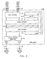
- Sort unit 104 includes a sort network 140 which sorts the 32 received packets into a sequence of packets based on activity bit 132 (FIG. 2) output switch designation 133 and priority field 135.
- Sort network 140 can be constructed in the manner described, for example, by Batcher in U. S. Patent No. 3,428,946 issued February 18, 1969 or as described by Huang et. al., in U. S. Patent No. 4,516,238 issued May 7, 1985.
- Sort network 140 sorts 32 received packets in accordance with the numerical significance of a "sort key" and produces an output of 32 packets in parallel in which those packets having the least significant sort key appear at one end (left) and those with the most significant sort key (right) at the other.
- the sort key is chosen to comprise, in sequence, the activity bit 132, the output switch destination 133 and the priority field 135 (FIG. 2) (it will be remembered that a priority field of 0 denotes the highest priority).
- the use of this sort key produces an output in which active packets are on the left and inactive packets are on the right and the active packets are grouped in accordance with their destination output switch and ordered within each group according to priority (highest priority on the left).
- the output packets from sort network 140 are applied to a merge network 141 which merges them with a plurality of packets from a delay unit 142.
- the packets from delay unit 142 comprise a sorted sequence of earlier received packets which were not transmitted to the outputs of sort unit 104 and their origins are discussed later herein.
- Merge network 141 is a sort network which although wider is constructed in the same manner as sort network 140 and which uses the same sort key as sort network 140. Accordingly, merge network 141 produces at its outputs 143 a sequence of packets in which active packets destined for the same output switch are grouped together and ordered within each group according to their priority and inactive packs are grouped to the right.
- the packets at the outputs at 143 of merge network 141 are applied as inputs to a trap network 144.
- Trap network 144 receives packets destined for the same output switch on adjacent ones of conductors 143 and passes the four highest priority packets destined for each output switch to an output switch selector 145. Specifically, when four or fewer packets are destined for a given output switch, e.g., 108 all of those packets are transmitted to the output switch selector 145 and when more than four packets are destined for a given output switch, the four of those packets having the highest priorities are sent to the output switch selector. The packets not sent to the output switch selector 145 are available for recirculation back to the inputs of merged network 141 via the delay unit 142.
- Trap network 144 selects those packets for transmission to the output switch selector 145, and designates packets over and above the selected number, should they exist, for recirculation. This may be accomplished, by the arrangement shown in FIG. 6.
- Each output port of merge network 141 (other than the last) is connected to a first input of a comparator 160 with which it is associated and to a second input of a comparator 160 associated with the adjacent output of merge network 141 in the direction of increasing sort key value (to the right).
- the last output of merge network 141 is connected only to its associated comparator 160.
- the comparator associated with the first (left-most) output of merge network 141 also has only one input.
- the other input is fixed at all “1's” to insure a "0" output (of course, a "0" output can be hard wired without the use of a comparator).
- the second output of merge network 141, line 161 is connected to the comparator 160 marked B and to comparator 160 marked C.
- the third output port of merge network 141, line 162 is also connected to comparator 160 marked C as well as the comparator marked D.
- each comparator 160 is either a "1" or a "0". It is a “1” when the output switch fields 133 of the packets applied to the comparator are the same, and it is "0" otherwise.
- Comparator 160 can be constructed from Exclusive OR gates and a flip-flop. In response to a set of output switch designations 0,0,1,2,3,4,4,4,4,4,6,6... the comparators yield the output signal set 0,1,0,0,0,0,1,1,1,1,0,1...
- the second layer in the trap network of FIG. 6 is a set of AND gates 166 and buffers 164. Again, there is a buffer 164 associated with each output of merge network 141 as well as an associated AND gate 166. Buffer 164 delays the output of merge network 141 and provides the delayed packet to a logic circuit 167.
- Each gate 166 is connected to its associated comparator and to a fixed number of previous adjacent comparators. The total number of inputs to each AND gate 166 is equal to the number of packets that is permitted to be applied by each sort unit, e.g., 104 simultaneously to an output switch, e.g., 108. In FIG. 4, that number is 4, and accordingly, each AND gate 166 is connected to its associated comparator and to three previous comparators (when they exist).
- AND gate 166 marked D is connected to outputs of comparators A, B, C and D.
- the size of buffer 164 is arranged to coincide with the completion of the comparison performed in comparators 160. At that time, the output of AND gate 166 is a "1" only if the two addresses applied to the relevant comparators are equal. That signal, together with the packet signal at the output of buffer 164, is appled to logic circuit 167.
- the outputs of AND gates 166 form the signal set 0,0,0,0,0,0,0,0,0,1,0,0.
- the only “1” in the above set is associated with the fifth packet that seeks to be connected to output switch "4". This fifth packet is not selected for transmission to output selector 145 and is made available for recirculation.
- Logic circuit 167 responds to a "0" from AND gate 166 by gating the packet from buffer 164 to a sorter 168 and responds to a "1" from AND gate 166 by gating the packet to delay 142 via a conductor 169.
- Logic circuits 167 receive packets in the same order that they leave merge network 141, that is, they are grouped in sequence based on output switch designation and ordered on priority (from left to right) within each group. Accordingly, the left most (highest priority) four packets of each group are sent to sorter 168 while the right most (lower priority) packets of each group, if they exist, are recirculated. Sorter 168 sorts the packets from logic circuits 167 into a sequence based on output switch designation to place consecutive packets on adjacent output paths and transmits them to output selector 145.
- the number of packets actually recirculated is a design choice which controls the cost and performance of the sort unit 104. Recirculating few packets, keeps the delay, merge and trap networks small which means that a significant number of packets may be dropped by the trap network 144. Alternatively, recirculating a large number of packets reduces the number of packets dropped but increases the cost and complexity of the delay, merge and trap networks since each of these networks must convey a larger number of packets. Delay unit 142 can be constructed to implement this design choice by selecting packets for recirculation.
- Output switch selector 145 responds to output switch designations to connect received packets to its output ports.
- the outputs of output switch selector 145 are connected to each output stage switch in groups of four. Each group being connected to one output stage switch as shown in FIG. 4.
- the left-most four outputs of switch selector 145 are connected to the output switch 108 and the right most four outputs of output switch selector 145 are connected to output switch 115.
- Output switch selector 145 responds to the output switch designation 133 of each received packet and gates the packet to one of the outputs in a group connected to the designated output switch, e.g., 108.
- the switching network of FIG. 1 includes eight output switches 108 through 115 each of which is substantially identical to the other output switches.
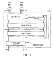
- FIG. 5 shows the block diagram structure of output switch 108 and represents the structure of all eight output switches 108 through 115.
- Output switch 108 includes a sort network 150 which receives four packets from each of the four sort units 104 through 107 by the previously described operation of sort units 104 through 107 and the connection paths 116.
- the packets sent to output switch 108 all include an output switch designation 133 (FIG. 2) defining output switch 108.
- Sort network 150 sorts the received packets into an ascending order sequence based on the output port specified in the output port field 134 (FIG. 2) of the packet and packet priority.
- the sorted packets are applied to a merge network 151 where they are merged with packets from a delay unit 152.
- the outputs 153 of the merge network 151 comprise the packets from sort network 150 and delay unit 152 arranged in sequence according to their destination output port with packets for the same destination being arranged by priority.
- the packets are connected via communication paths 153 to a trap network 154. Trap network 154 selects the highest priority packet destined for each of the 16 output ports of the output switch 108.
- the selected packets are applied to an output port selector 155 which operates as an expansion network to connect each packet to its destination output port.
- the packets, which are not transmitted to the output port selector 155 are recirculated to the inputs of delay unit 152 for later merge with the new sequence of packets from sort network 150.
Landscapes
- Engineering & Computer Science (AREA)
- Computer Networks & Wireless Communication (AREA)
- Signal Processing (AREA)
- Data Exchanges In Wide-Area Networks (AREA)
Applications Claiming Priority (2)
| Application Number | Priority Date | Filing Date | Title |
|---|---|---|---|
| US07/287,775 US4899335A (en) | 1988-12-21 | 1988-12-21 | Self routing packet switching network architecture |
| US287775 | 1994-08-09 |
Publications (3)
| Publication Number | Publication Date |
|---|---|
| EP0375249A2 true EP0375249A2 (de) | 1990-06-27 |
| EP0375249A3 EP0375249A3 (de) | 1991-07-24 |
| EP0375249B1 EP0375249B1 (de) | 1995-02-22 |
Family
ID=23104295
Family Applications (1)
| Application Number | Title | Priority Date | Filing Date |
|---|---|---|---|
| EP89312974A Expired - Lifetime EP0375249B1 (de) | 1988-12-21 | 1989-12-12 | Aufbau für selbstleitweglenkendes Paketvermittlungsnetz |
Country Status (6)
| Country | Link |
|---|---|
| US (1) | US4899335A (de) |
| EP (1) | EP0375249B1 (de) |
| JP (1) | JPH02185140A (de) |
| CA (1) | CA1319410C (de) |
| DE (1) | DE68921312T2 (de) |
| ES (1) | ES2068254T3 (de) |
Cited By (5)
| Publication number | Priority date | Publication date | Assignee | Title |
|---|---|---|---|---|
| EP1061695A3 (de) * | 1999-05-18 | 2004-05-19 | Alcatel Internetworking, Inc. | Verfahren und Einrichtung zur Erhaltung der Reihenfolgenintegrität von Paketen in einem parellel arbeitenden Vermittler |
| EP2972912A4 (de) * | 2013-03-15 | 2016-11-09 | Soft Machines Inc | Verfahren zur implementierung einer zeilengeschwindigkeitsverbindungsstruktur |
| US9817666B2 (en) | 2013-03-15 | 2017-11-14 | Intel Corporation | Method for a delayed branch implementation by using a front end track table |
| US10282170B2 (en) | 2013-03-15 | 2019-05-07 | Intel Corporation | Method for a stage optimized high speed adder |
| US11003459B2 (en) | 2013-03-15 | 2021-05-11 | Intel Corporation | Method for implementing a line speed interconnect structure |
Families Citing this family (29)
| Publication number | Priority date | Publication date | Assignee | Title |
|---|---|---|---|---|
| US5105424A (en) * | 1988-06-02 | 1992-04-14 | California Institute Of Technology | Inter-computer message routing system with each computer having separate routinng automata for each dimension of the network |
| EP0384936B1 (de) * | 1989-03-03 | 1994-06-15 | Siemens Aktiengesellschaft | Verfahren und Schaltungsanordnung zum Weiterleiten von auf Zubringerleitungen übertragenen Nachrichtenpaketen über eine Paketvermittlungseinrichtung |
| CA1320257C (en) * | 1989-04-20 | 1993-07-13 | Ernst August Munter | Method and apparatus for input-buffered asynchronous transfer mode switching |
| US5148428A (en) * | 1989-05-02 | 1992-09-15 | Bell Communictions Research, Inc. | Modular architecture for very large packet switch |
| DE3942977A1 (de) * | 1989-12-23 | 1991-06-27 | Standard Elektrik Lorenz Ag | Verfahren zum wiederherstellen der richtigen zellfolge, insbesondere in einer atm-vermittlungsstelle, sowie ausgangseinheit hierfuer |
| CA2048198C (en) * | 1990-08-09 | 1996-06-04 | Kai Y. Eng | Growable switch |
| US5172371A (en) * | 1990-08-09 | 1992-12-15 | At&T Bell Laboratories | Growable switch |
| US5197064A (en) * | 1990-11-26 | 1993-03-23 | Bell Communications Research, Inc. | Distributed modular packet switch employing recursive partitioning |
| US5179552A (en) * | 1990-11-26 | 1993-01-12 | Bell Communications Research, Inc. | Crosspoint matrix switching element for a packet switch |
| US5124978A (en) * | 1990-11-26 | 1992-06-23 | Bell Communications Research, Inc. | Grouping network based non-buffer statistical multiplexor |
| US5166930A (en) * | 1990-12-17 | 1992-11-24 | At&T Bell Laboratories | Data channel scheduling discipline arrangement and method |
| EP0491069A1 (de) * | 1990-12-18 | 1992-06-24 | International Business Machines Corporation | Verfahren zur selektiven Datenverteilung mit Einweg-Rundfunkübertragung oder Sendung |
| US5130984A (en) * | 1990-12-18 | 1992-07-14 | Bell Communications Research, Inc. | Large fault tolerant packet switch particularly suited for asynchronous transfer mode (ATM) communication |
| US5166926A (en) * | 1990-12-18 | 1992-11-24 | Bell Communications Research, Inc. | Packet address look-ahead technique for use in implementing a high speed packet switch |
| US5157654A (en) * | 1990-12-18 | 1992-10-20 | Bell Communications Research, Inc. | Technique for resolving output port contention in a high speed packet switch |
| US5341369A (en) * | 1992-02-11 | 1994-08-23 | Vitesse Semiconductor Corp. | Multichannel self-routing packet switching network architecture |
| US5274642A (en) * | 1992-06-05 | 1993-12-28 | Indra Widjaja | Output buffered packet switch with a flexible buffer management scheme |
| GB2271250B (en) * | 1992-10-01 | 1996-07-10 | Digital Equipment Int | Message network monitoring |
| JPH0775353B2 (ja) * | 1993-02-23 | 1995-08-09 | 日本電気株式会社 | パケット交換方式 |
| US5440549A (en) * | 1993-04-22 | 1995-08-08 | Washington University | Broadband multi-channel switch with multicasting capability |
| US5450578A (en) * | 1993-12-23 | 1995-09-12 | Unisys Corporation | Method and apparatus for automatically routing around faults within an interconnect system |
| US5495589A (en) * | 1993-12-23 | 1996-02-27 | Unisys Corporation | Architecture for smart control of bi-directional transfer of data |
| US6757284B1 (en) * | 2000-03-07 | 2004-06-29 | Cisco Technology, Inc. | Method and apparatus for pipeline sorting of ordered streams of data items |
| US7974191B2 (en) * | 2004-03-10 | 2011-07-05 | Alcatel-Lucent Usa Inc. | Method, apparatus and system for the synchronized combining of packet data |
| JP2006285811A (ja) * | 2005-04-04 | 2006-10-19 | Hitachi Ltd | ストレージシステム及びデータ処理方法 |
| US8085659B2 (en) * | 2007-08-28 | 2011-12-27 | Universidad Politecnica De Valencia | Method and switch for routing data packets in interconnection networks |
| US9807004B2 (en) * | 2014-04-01 | 2017-10-31 | Google Inc. | System and method for software defined routing of traffic within and between autonomous systems with enhanced flow routing, scalability and security |
| US10523596B1 (en) * | 2015-02-06 | 2019-12-31 | Xilinx, Inc. | Circuits for and methods of merging streams of data to generate sorted output data |
| US12598142B2 (en) * | 2023-10-06 | 2026-04-07 | Mellanox Technologies, Ltd. | Packet load-balancing |
Family Cites Families (3)
| Publication number | Priority date | Publication date | Assignee | Title |
|---|---|---|---|---|
| US4516238A (en) * | 1983-03-28 | 1985-05-07 | At&T Bell Laboratories | Self-routing switching network |
| US4621359A (en) * | 1984-10-18 | 1986-11-04 | Hughes Aircraft Company | Load balancing for packet switching nodes |
| JPS63135039A (ja) * | 1986-11-26 | 1988-06-07 | Nippon Telegr & Teleph Corp <Ntt> | 待ち合わせ形スイツチ網の経路選択制御方法 |
-
1988
- 1988-12-21 US US07/287,775 patent/US4899335A/en not_active Expired - Lifetime
-
1989
- 1989-09-29 CA CA000614716A patent/CA1319410C/en not_active Expired - Fee Related
- 1989-12-12 ES ES89312974T patent/ES2068254T3/es not_active Expired - Lifetime
- 1989-12-12 DE DE68921312T patent/DE68921312T2/de not_active Expired - Fee Related
- 1989-12-12 EP EP89312974A patent/EP0375249B1/de not_active Expired - Lifetime
- 1989-12-19 JP JP1329393A patent/JPH02185140A/ja active Pending
Non-Patent Citations (2)
| Title |
|---|
| IEEE GLOBAL TELECOMMUNICATIONS CONFERENCE PROCEEDINGS, vol. 1, November 1984, pages 121-125, IEEE, New York, US; A. HUANG et al.: "STARLITE: A wideband digital switch" * |
| IEEE JOURNAL ON SELECTED AREAS IN COMMUNICATIONS, vol. SAC-5, no. 8, October 1987, pages 1264-1273, IEEE, New York, US; J.Y. HUI et al.: "A broadband packet switch for integrated transport" * |
Cited By (8)
| Publication number | Priority date | Publication date | Assignee | Title |
|---|---|---|---|---|
| EP1061695A3 (de) * | 1999-05-18 | 2004-05-19 | Alcatel Internetworking, Inc. | Verfahren und Einrichtung zur Erhaltung der Reihenfolgenintegrität von Paketen in einem parellel arbeitenden Vermittler |
| EP2972912A4 (de) * | 2013-03-15 | 2016-11-09 | Soft Machines Inc | Verfahren zur implementierung einer zeilengeschwindigkeitsverbindungsstruktur |
| US9740499B2 (en) | 2013-03-15 | 2017-08-22 | Intel Corporation | Method for implementing a line speed interconnect structure |
| US9817666B2 (en) | 2013-03-15 | 2017-11-14 | Intel Corporation | Method for a delayed branch implementation by using a front end track table |
| US10282170B2 (en) | 2013-03-15 | 2019-05-07 | Intel Corporation | Method for a stage optimized high speed adder |
| US10303484B2 (en) | 2013-03-15 | 2019-05-28 | Intel Corporation | Method for implementing a line speed interconnect structure |
| US10908913B2 (en) | 2013-03-15 | 2021-02-02 | Intel Corporation | Method for a delayed branch implementation by using a front end track table |
| US11003459B2 (en) | 2013-03-15 | 2021-05-11 | Intel Corporation | Method for implementing a line speed interconnect structure |
Also Published As
| Publication number | Publication date |
|---|---|
| CA1319410C (en) | 1993-06-22 |
| EP0375249B1 (de) | 1995-02-22 |
| US4899335A (en) | 1990-02-06 |
| DE68921312T2 (de) | 1995-09-28 |
| EP0375249A3 (de) | 1991-07-24 |
| JPH02185140A (ja) | 1990-07-19 |
| DE68921312D1 (de) | 1995-03-30 |
| ES2068254T3 (es) | 1995-04-16 |
Similar Documents
| Publication | Publication Date | Title |
|---|---|---|
| EP0375249B1 (de) | Aufbau für selbstleitweglenkendes Paketvermittlungsnetz | |
| KR100211123B1 (ko) | 고속 패킷 스위칭을 위한 다단 상호 연결 망 | |
| US5406556A (en) | Output buffered packet switch with a flexible buffer management scheme | |
| EP0761071B1 (de) | Optisches telekommunikationsnetz | |
| US4734907A (en) | Broadcast packet switching network | |
| CA1207418A (en) | Self-routing switching network | |
| US4866701A (en) | Packet switch with dynamic allocation of inputs | |
| US7397808B2 (en) | Parallel switching architecture for multiple input/output | |
| EP0405208B1 (de) | Mehrstufiges Netz mit verteilter Steuerung | |
| US5617413A (en) | Scalable wrap-around shuffle exchange network with deflection routing | |
| US7167481B2 (en) | Technique for computing pathways in a multi-stage switch fabric through exploitation of symmetrical links | |
| EP0542233A2 (de) | Einrichtung und Verfahren zur Zellenvermittlung | |
| EP0306291B1 (de) | Kommunikationsvermittlungselement | |
| JPH02154547A (ja) | 同報通信回路網 | |
| Liew et al. | A 3-stage interconnection structure for very large packet switches | |
| US5216420A (en) | Matrix sorting network for sorting N inputs onto N outputs | |
| EP1326384B1 (de) | Verfahren zur Berechnung der Wege in einer mehrstufigen Vermittlungsstelle mittels Ausnutzung der symmetrischen Verbindungen | |
| Weng et al. | Solution for packet switching of broadband ISDN | |
| Giacopelli et al. | Scalability study of self-routing packet switch fabrics for very large scale broadband ISDN central offices | |
| CA2544414A1 (en) | Nonblocking and deterministic multirate unicast packet scheduling | |
| Mirfakhraei | Performance analysis of a large-scale switching system for high-speed ATM networks | |
| Zarour et al. | The closed loop bridged shuffle-exchange network: a high performance self-routing ATM switch | |
| Jajszczyk et al. | Optimum structures and growability of shared-buffer fabrics | |
| Park et al. | FBSF: A New Fast Packet Switching Fabric Based on Multistage Interconnection Network with Multiple Outlets | |
| Mir | Performance evaluation of efficient multipath crossbars |
Legal Events
| Date | Code | Title | Description |
|---|---|---|---|
| PUAI | Public reference made under article 153(3) epc to a published international application that has entered the european phase |
Free format text: ORIGINAL CODE: 0009012 |
|
| AK | Designated contracting states |
Kind code of ref document: A2 Designated state(s): DE ES FR GB IT |
|
| PUAL | Search report despatched |
Free format text: ORIGINAL CODE: 0009013 |
|
| AK | Designated contracting states |
Kind code of ref document: A3 Designated state(s): DE ES FR GB IT |
|
| 17P | Request for examination filed |
Effective date: 19920115 |
|
| 17Q | First examination report despatched |
Effective date: 19931202 |
|
| RAP3 | Party data changed (applicant data changed or rights of an application transferred) |
Owner name: AT&T CORP. |
|
| GRAA | (expected) grant |
Free format text: ORIGINAL CODE: 0009210 |
|
| AK | Designated contracting states |
Kind code of ref document: B1 Designated state(s): DE ES FR GB IT |
|
| ET | Fr: translation filed | ||
| REF | Corresponds to: |
Ref document number: 68921312 Country of ref document: DE Date of ref document: 19950330 |
|
| REG | Reference to a national code |
Ref country code: ES Ref legal event code: FG2A Ref document number: 2068254 Country of ref document: ES Kind code of ref document: T3 |
|
| ITF | It: translation for a ep patent filed | ||
| PLBE | No opposition filed within time limit |
Free format text: ORIGINAL CODE: 0009261 |
|
| STAA | Information on the status of an ep patent application or granted ep patent |
Free format text: STATUS: NO OPPOSITION FILED WITHIN TIME LIMIT |
|
| 26N | No opposition filed | ||
| PGFP | Annual fee paid to national office [announced via postgrant information from national office to epo] |
Ref country code: FR Payment date: 20011121 Year of fee payment: 13 |
|
| PGFP | Annual fee paid to national office [announced via postgrant information from national office to epo] |
Ref country code: GB Payment date: 20011126 Year of fee payment: 13 |
|
| PGFP | Annual fee paid to national office [announced via postgrant information from national office to epo] |
Ref country code: ES Payment date: 20011204 Year of fee payment: 13 |
|
| PGFP | Annual fee paid to national office [announced via postgrant information from national office to epo] |
Ref country code: DE Payment date: 20011230 Year of fee payment: 13 |
|
| REG | Reference to a national code |
Ref country code: GB Ref legal event code: IF02 |
|
| PG25 | Lapsed in a contracting state [announced via postgrant information from national office to epo] |
Ref country code: GB Free format text: LAPSE BECAUSE OF NON-PAYMENT OF DUE FEES Effective date: 20021212 |
|
| PG25 | Lapsed in a contracting state [announced via postgrant information from national office to epo] |
Ref country code: ES Free format text: LAPSE BECAUSE OF NON-PAYMENT OF DUE FEES Effective date: 20021213 |
|
| PG25 | Lapsed in a contracting state [announced via postgrant information from national office to epo] |
Ref country code: DE Free format text: LAPSE BECAUSE OF NON-PAYMENT OF DUE FEES Effective date: 20030701 |
|
| GBPC | Gb: european patent ceased through non-payment of renewal fee | ||
| PG25 | Lapsed in a contracting state [announced via postgrant information from national office to epo] |
Ref country code: FR Free format text: LAPSE BECAUSE OF NON-PAYMENT OF DUE FEES Effective date: 20030901 |
|
| REG | Reference to a national code |
Ref country code: FR Ref legal event code: ST |
|
| REG | Reference to a national code |
Ref country code: ES Ref legal event code: FD2A Effective date: 20021213 |
|
| PG25 | Lapsed in a contracting state [announced via postgrant information from national office to epo] |
Ref country code: IT Free format text: LAPSE BECAUSE OF NON-PAYMENT OF DUE FEES;WARNING: LAPSES OF ITALIAN PATENTS WITH EFFECTIVE DATE BEFORE 2007 MAY HAVE OCCURRED AT ANY TIME BEFORE 2007. THE CORRECT EFFECTIVE DATE MAY BE DIFFERENT FROM THE ONE RECORDED. Effective date: 20051212 |