EP0375252A2 - Dynamomètre à poulies multiples et procédé d'essai - Google Patents
Dynamomètre à poulies multiples et procédé d'essai Download PDFInfo
- Publication number
- EP0375252A2 EP0375252A2 EP89312977A EP89312977A EP0375252A2 EP 0375252 A2 EP0375252 A2 EP 0375252A2 EP 89312977 A EP89312977 A EP 89312977A EP 89312977 A EP89312977 A EP 89312977A EP 0375252 A2 EP0375252 A2 EP 0375252A2
- Authority
- EP
- European Patent Office
- Prior art keywords
- cable
- tension
- roller sheave
- sheave
- elongate element
- Prior art date
- Legal status (The legal status is an assumption and is not a legal conclusion. Google has not performed a legal analysis and makes no representation as to the accuracy of the status listed.)
- Ceased
Links
Images


Classifications
-
- G—PHYSICS
- G01—MEASURING; TESTING
- G01L—MEASURING FORCE, STRESS, TORQUE, WORK, MECHANICAL POWER, MECHANICAL EFFICIENCY, OR FLUID PRESSURE
- G01L5/00—Apparatus for, or methods of, measuring force, work, mechanical power, or torque, specially adapted for specific purposes
- G01L5/04—Apparatus for, or methods of, measuring force, work, mechanical power, or torque, specially adapted for specific purposes for measuring tension in flexible members, e.g. ropes, cables, wires, threads, belts or bands
- G01L5/10—Apparatus for, or methods of, measuring force, work, mechanical power, or torque, specially adapted for specific purposes for measuring tension in flexible members, e.g. ropes, cables, wires, threads, belts or bands using electrical means
- G01L5/108—Apparatus for, or methods of, measuring force, work, mechanical power, or torque, specially adapted for specific purposes for measuring tension in flexible members, e.g. ropes, cables, wires, threads, belts or bands using electrical means for measuring a reaction force applied on a single support, e.g. a glider
-
- G—PHYSICS
- G01—MEASURING; TESTING
- G01L—MEASURING FORCE, STRESS, TORQUE, WORK, MECHANICAL POWER, MECHANICAL EFFICIENCY, OR FLUID PRESSURE
- G01L5/00—Apparatus for, or methods of, measuring force, work, mechanical power, or torque, specially adapted for specific purposes
- G01L5/04—Apparatus for, or methods of, measuring force, work, mechanical power, or torque, specially adapted for specific purposes for measuring tension in flexible members, e.g. ropes, cables, wires, threads, belts or bands
- G01L5/10—Apparatus for, or methods of, measuring force, work, mechanical power, or torque, specially adapted for specific purposes for measuring tension in flexible members, e.g. ropes, cables, wires, threads, belts or bands using electrical means
-
- G—PHYSICS
- G02—OPTICS
- G02B—OPTICAL ELEMENTS, SYSTEMS OR APPARATUS
- G02B6/00—Light guides; Structural details of arrangements comprising light guides and other optical elements, e.g. couplings
- G02B6/46—Processes or apparatus adapted for installing or repairing optical fibres or optical cables
- G02B6/50—Underground or underwater installation; Installation through tubing, conduits or ducts
Definitions
- This invention relates to a dynamometer and a method of using the same.
- the process of sliding the cable over the friction plate of a dynamometer is a source of error in the tension measurement.
- the metal friction plate provides a chute through which the cable slides. That plate wears as the cable slides through and is gouged and nicked as chains and fittings are handled. After these defects are incurred, the dynamometer produces erroneous tension readings because of slight changes in the cable deflection angle resulting from the wear and tear. Additional error in the tension reading is caused by the force of friction between the cable and the friction plate, as the cable slides over it. This force is greatly dependent upon the coefficient of friction between the cable and the friction plate. Error signals, arising from all of the aforementioned sources of error, are superimposed on the desired tension signal detected by the load cell. Together, all of these signals are amplified and applied to a readout device.
- the resulting tension reading includes inaccuracies which are acceptable for undersea cables containing coaxial copper transmission media. Such inaccuracies are acceptable because copper is a malleable material that will stretch readily without breaking if a desired maximum tension is exceeded for brief periods.
- optical fibers are being substituted for the coaxial copper transmission media.
- the optical fibers are much more fragile than the copper.
- Maximum allowable tension in the resulting optical fiber cable is critical because the optical fibers stretch very little without breaking. Acceptable error in tension readings on optical fiber cables is very low. Thus it is necessary to substantially reduce the sources of errors encountered when making tension measurements with a dynamometer.
- a multi-roller sheave is interposed between a cable supply and the cable destination that the cable rolls over the multi-roller sheave. While the cable is rolling over the sheave, the center axis of the cable changes direction from one side of the multi-roller sheave to the other side. Tension in the cable produces a force against the sheave, causes the multi-roller sheave to move and strain a strain gauge. A signal produced by the strain gauge is amplified into a signal that accurately indicates the magnitude of tension in the cable.
- the method includes the steps of (1) pulling the cable to roll over a multi-roller sheave so that the center axis of the cable changes direction from one side of the multi-roller sheave to the other side; (2) in response to the tension in the cable and change of direction of the center axis, moving the multi-roller sheave a distance related to the magnitude of the tension in the cable; (3) straining a strain gauge in proportion to the distance the multi-roller sheave moves; and (4) producing a signal proportional to the strain in the strain gauge for indicating the magnitude of tension in the cable.
- the apparatus and method can be used for measuring tension during the manufacture or use of many other elongate items, e.g., lines, strings, ribbons, filaments, threads, strands, fibers, ropes, hoses, tubes, wires and others.
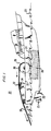
- FIG. 1 there is shown a diagram of the stern section 20 of an undersea cable laying ship.
- a propeller 22 provides thrust for moving the ship through ocean water 23.
- a rudder is positioned for steering.
- In the hold of the ship there is an open tank 27 for storing a very long length of cable 28.
- the cable 28 is pulled up out of the tank 27, bent around a smooth guide surface 30, and moved toward the stern for deployment to the bottom of the ocean.
- the cable 28 is pulled from the ship and is deployed to the bottom of the ocean.
- the cable 28 rolls over a multi-roller sheave 37 which is part of the dynamometer.
- the cable bends and changes the direction of the center axis of the cable.
- This change of direction of the cable center axis produces a vertical, downwardly directed force on the dynamometer 34. That force is proportional to the force of tension in the cable 28.
- the dynamometer 34 is arranged to produce a signal accurately representing the magnitude of tension in the cable 28.
- FIG. 1 shows only deployment of cable over the stern of a ship, deployment over the bow and recovery of cable over the stern or bow are accomplished with similar dynamometer arrangements. Details of the dynamometer 34, the multi-roller sheave 37 and the on-deck mounting arrangements thereof for FIG. 1 are presented in FIGS. 2, 3, 4, 5, and 6.
- FIG. 2 there is shown a solid steel base plate 50 with mounting brackets 52 affixed under each corner.
- the plate 50 forms a solid base for affixing the multi-roller sheave 37, which is shown in detail in FIG. 5.
- Two side cantilever rods 53 and two end cantilever rods 55 are fixed to the ship deck, or to a platform mounted to the deck, by brackets 57.
- the opposite ends of the cantilever rods 53 and 55 are inserted into the mounting brackets 52.
- a load cell 58 is interposed between the steel base plate 50 and the ship deck.
- a vertical force, imparted from the multi-roller sheave 37 of FIG. 5 to the steel base plate 50 of FIG. 2 is divided proportionally among the four cantilever rods and the load cell 58.
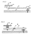
- FIG. 3 shows the arrangement of the cantilever rod 53 spring in a clearer sideview.
- the cantilever rod 53 At one end of the cantilever rod 53, it is inserted into the mounting bracket 52 that is affixed to the steel base plate 50. The other end of the cantilever rod 53 is held in the clamping bracket 57 which is fixed to the deck or platform 33.
- a force 59 one portion of the force created by the tension in the cable 28 of FIG. 1, is applied downward vertically so as to deflect the cantilever rod 53.
- the free end of the rod 53 deflects a vertical distance that is proportional to the magnitude of the force 59.
- Cantilever rod springs are used to provide side-to-side and end-to-end stiffening for preventing the base plate 50 and the multi-roller sheave from swaying in response to a misaligned cable rolling through the sheave, or to pitch and roll motion of the ship.
- FIG. 4 there are shown details of the bending beam load cell 58 which is mounted between the ship deck or platform 33 and the steel base plate 50.
- a package 60 containing a strain gauge, arranged in a Wheatstone bridge, is affixed to a flexible steel bar of the load cell 58.
- a downwardly directed force 62 represents a portion of the whole force from the multi-roller sheave 37 of FIG. 5. This portion of the force is applied to the bending beam load cell 58 for deflecting it.
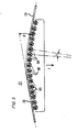
- FIG. 5 there is shown a detailed sideview of the multi-roller sheave 37 of FIG. 1.
- the cable 28 bends over the sheave 37 so that the center axis of the cable changes direction by an angle ⁇ .
- the force F on the multi-roller sheave 37 is directly proportional to the tension T in the cable, as represented by the expression
- the axes 65 of several steel rollers 68 are positioned on the circumference of a circle with a very large radius ⁇ relative to the diameters of the rollers.
- the cable passes over the rollers, which are free to rotate, reducing friction between the cable and the sheave to nil.
- Spacing between the rollers is chosen so that the cable 28 is constrained to a bending radius at all points along the multi-roller sheave 37 that exceeds the minimum bending radius for the cable.
- An arrow F, representing the force resulting from tension in the cable 28, is directed downward vertically toward the steel base plate 50 of FIG. 2.
- ⁇ radius of curvature
- dR the derivative of the curvature
- t angle between rollers
- dt the derivative of the angle between rollers
- EI cable bending stiffness
- T cable tension
- rollers 68 shown in FIG. 5
- other rollers mounted on vertically oriented axes may be installed along both sides of the sheave 37 to further reduce friction between the cable and the sheave. These rollers with the vertical axis are positioned for the same conditions as the rollers on the horizontal axes.
- FIG. 6 shows a Wheatstone bridge arrangement for detecting strain in the strain gauge which is fixed to the bending beam of the load cell 58 of FIG. 4.
- FIG. 6 there are two fixed resistors R1 and R2, an adjustable resistor R3, and a strain gauge variable resistance RG.
- Those are configured in a classical bridge arrangement with a source of d.c. voltage 70 connected between two diagonally opposite nodes 71 and 72 of the bridge. Output voltage from the bridge is taken from nodes 73 and 74 and is amplified through an amplifier 78. The amplified output is applied to a meter 80 for indicating the magnitude of the bridge output which accurately represents strain in the strain gauge resistor RG and tension in the cable 28 of FIGS. 1 and 5.
- strain gauge resistor RG is the only resistance which varies in the bridge.
- the resistor RG should vary only in response to changes in the strain of the bending beam load cell 58 of FIG. 4.
- Initial balancing of the bridge is accomplished by adjusting the resistor R3 until the output voltage is zeroed. Thereafter readings on the meter 80 are directly related to changes in the strain of the strain gauge resistor RG and can be calibrated to represent the tension in the cable 28.
- a source reel, drum, or spool 90 continuously supplies an elongate element 92, such as a filament, thread, fiber, string, stranded cable, rope, tube, hose, wire, line, ribbon, or optical fiber cable, for some purpose such as a manufacturing process, construction process, testing, or inspection.
- a block 93 represents the station or stations of a manufacturing or testing process along the path that the elongate element travels to a takeup reel 95.
- the elongate element 92 rolls over a multi-roller sheave 97 where the center axis of the elongate element 92 changes direction, or is displaced, by a displacement angle ⁇ .
- Friction between the elongate element 92 and the multi-roller sheave 97 is negligible because the element rolls over the rollers.
- Tension in the elongate element 92 causes a force 100 which is directed vertically downward on the multi-roller sheave 97.
- a load cell 102 including a strain gauge is strained by the force 100 directly proportional to the tension in the elongate element 92.
- the load cell produces an output signal at a meter 105 in response to the strain of the load cell. That signal has a magnitude directly proportional to the magnitude of the tension in the elongate element 72. Error caused by the force of friction between the elongate element and the sheave 97 is negligible.
Landscapes
- Physics & Mathematics (AREA)
- General Physics & Mathematics (AREA)
- Optics & Photonics (AREA)
- Force Measurement Appropriate To Specific Purposes (AREA)
Applications Claiming Priority (2)
| Application Number | Priority Date | Filing Date | Title |
|---|---|---|---|
| US07/287,420 US4914960A (en) | 1988-12-20 | 1988-12-20 | Multi-roller dynamometer and test method |
| US287420 | 1988-12-20 |
Publications (2)
| Publication Number | Publication Date |
|---|---|
| EP0375252A2 true EP0375252A2 (fr) | 1990-06-27 |
| EP0375252A3 EP0375252A3 (fr) | 1991-04-24 |
Family
ID=23102825
Family Applications (1)
| Application Number | Title | Priority Date | Filing Date |
|---|---|---|---|
| EP19890312977 Ceased EP0375252A3 (fr) | 1988-12-20 | 1989-12-12 | Dynamomètre à poulies multiples et procédé d'essai |
Country Status (5)
| Country | Link |
|---|---|
| US (1) | US4914960A (fr) |
| EP (1) | EP0375252A3 (fr) |
| JP (1) | JPH02213735A (fr) |
| AU (1) | AU613816B2 (fr) |
| CA (1) | CA2001860C (fr) |
Families Citing this family (15)
| Publication number | Priority date | Publication date | Assignee | Title |
|---|---|---|---|---|
| US5275062A (en) * | 1991-08-09 | 1994-01-04 | T. Sendzimir, Inc. | Web tension measuring device for use with web coiling equipment |
| DE4226791C2 (de) * | 1992-08-13 | 1995-07-13 | Koenig & Bauer Ag | Einrichtung zum Messen einer Bahnspannung einer Warenbahn |
| US5368375A (en) * | 1993-08-24 | 1994-11-29 | Caterpillar Inc. | Belt tension indicating system |
| US5454272A (en) * | 1994-02-07 | 1995-10-03 | Ihs Engineering, Inc. | Cable tensioning device |
| DE59405907D1 (de) * | 1994-06-10 | 1998-06-10 | Rueti Ag Maschf | Vorrichtung zum Messen der Fadenspannung und Webmaschine |
| FI101017B (fi) * | 1996-03-29 | 1998-03-31 | Soundek Oy | Optisen kuidun vetojännityksen mittari |
| ES2246618B1 (es) * | 2002-12-23 | 2007-06-01 | Universitat Politecnica De Catalunya | Conjunto de remolque, y equipo y procedimiento de medida de la tension de un cable de un conjunto de remolque. |
| US6877720B1 (en) * | 2003-02-18 | 2005-04-12 | Industrial Sensors and Instruments, Inc. | Compact geometry tensiometer using a segmented sheave assembly |
| BRPI0800473B1 (pt) * | 2008-03-05 | 2020-04-22 | Petroleo Brasileiro S.A. - Petrobras | sistema e processo para detecção de vazamento em umbilicais |
| CN104428231B (zh) * | 2012-06-29 | 2016-09-07 | 因温特奥股份公司 | 电梯设备 |
| DE102013014265A1 (de) * | 2013-08-27 | 2015-03-05 | Liebherr-Components Biberach Gmbh | Vorrichtung zur Erkennung der Ablegereife eines hochfesten Faserseils beim Einsatz an Hebezeugen |
| CN108144961A (zh) * | 2015-11-13 | 2018-06-12 | 芜湖楚江合金铜材有限公司 | 铜合金成型设备 |
| US10782198B2 (en) | 2016-07-06 | 2020-09-22 | Greenlee Texron Inc. | Pulley assembly with gauge device and communication environment for messaging |
| EP3487018A1 (fr) | 2017-11-15 | 2019-05-22 | Siemens Gamesa Renewable Energy A/S | Structure en mer et procédé de fixation d'un tube ou d'un câble à un appareil d'une structure en mer |
| US11473989B2 (en) * | 2018-07-31 | 2022-10-18 | Illinois Tool Works Inc. | Multi-dimensional sheave for use in tension measurement systems |
Family Cites Families (13)
| Publication number | Priority date | Publication date | Assignee | Title |
|---|---|---|---|---|
| US2444245A (en) * | 1946-05-01 | 1948-06-29 | Gen Electric | Tension measuring device |
| US3204454A (en) * | 1962-02-21 | 1965-09-07 | Asea Ab | Means for measuring the tension in a strip or sheet shaped material |
| GB1038170A (en) * | 1963-10-16 | 1966-08-10 | Weighload Ltd | Improvements in dynamometers |
| SE307463B (fr) * | 1966-12-30 | 1969-01-07 | Arenco Electronics Ab | |
| US3801071A (en) * | 1972-10-06 | 1974-04-02 | Byran Jackson Inc | Towing winch control system |
| JPS5914370B2 (ja) * | 1978-10-30 | 1984-04-04 | 富士重工業株式会社 | 架線延線車装置 |
| US4417718A (en) * | 1979-12-20 | 1983-11-29 | Niskin Shale J | Counter balanced sheave assembly with multiple pulleys |
| US4492363A (en) * | 1979-12-20 | 1985-01-08 | Niskin Shale J | Multiple pulley sheave assembly with retainer pulleys |
| US4301995A (en) * | 1979-12-20 | 1981-11-24 | Niskin Shale J | Counter-balanced sheave |
| US4690380A (en) * | 1986-01-30 | 1987-09-01 | General Oceanics, Inc. | Sheave assembly with multiple pulleys used to measure cable angle |
| NO164132C (no) * | 1986-03-10 | 1990-08-29 | Alcatel Stk As | Fremgangsmaate og maaleutstyr for utlegning av elektriske sterkstroemkabler. |
| US4708321A (en) * | 1986-06-05 | 1987-11-24 | Niskin Shale J | Multiple sheave assembly with angled rollers |
| NO164371C (no) * | 1987-07-27 | 1990-09-26 | Kvaerner Subsea Contracting | Fremg ved fremst og legging av en roerledn eller en kabel under vann, fartoey til bruk ved legging under vann av en paa en trommel ombord i fartoeyet kveilet ledning, og landbase for fremst av en roerledn som kveiles paa en trommel. |
-
1988
- 1988-12-20 US US07/287,420 patent/US4914960A/en not_active Expired - Lifetime
-
1989
- 1989-10-31 CA CA002001860A patent/CA2001860C/fr not_active Expired - Lifetime
- 1989-12-12 EP EP19890312977 patent/EP0375252A3/fr not_active Ceased
- 1989-12-19 AU AU47023/89A patent/AU613816B2/en not_active Expired
- 1989-12-20 JP JP1328575A patent/JPH02213735A/ja active Pending
Also Published As
| Publication number | Publication date |
|---|---|
| AU4702389A (en) | 1990-06-28 |
| AU613816B2 (en) | 1991-08-08 |
| US4914960A (en) | 1990-04-10 |
| CA2001860A1 (fr) | 1990-06-12 |
| CA2001860C (fr) | 1999-12-14 |
| EP0375252A3 (fr) | 1991-04-24 |
| JPH02213735A (ja) | 1990-08-24 |
Similar Documents
| Publication | Publication Date | Title |
|---|---|---|
| US4914960A (en) | Multi-roller dynamometer and test method | |
| AU2007200493B2 (en) | Fiber optic strain gauge and cable strain monitoring system for marine seismic acquisition systems | |
| US7424832B1 (en) | Cable tensiometer for aircraft | |
| US8335126B2 (en) | Method for compensating marine geophysical sensor measurements for effects of streamer elongation | |
| US3482439A (en) | Tensile testing apparatus | |
| KR20180138150A (ko) | 엘리베이터 카 하중의 표시를 제공하는 엘리베이터 종단 조립체 | |
| CN115072491A (zh) | 一种线缆套管动态张力读取装置及调节装置 | |
| US5000619A (en) | Apparatus for laying or recovering an undersea optical fiber cable | |
| JPH02242951A (ja) | 織機のたて糸張力測定装置 | |
| US4043190A (en) | Mass and force meter | |
| EP0551115B1 (fr) | Dispositif pour mesurer des efforts de tension d'une fibre optique ou d'un fil correspondent par moyen d'excursion acoustique | |
| WO1996017233A1 (fr) | Technique et appareil de mesure des forces sur deux axes et application a la mesure de la force de traction et d'un angle de deflexion variable dans un motif continu | |
| US20250035429A1 (en) | Device for measuring bending of an elongate vertically oriented channel | |
| US4933917A (en) | Means for monitoring the laying of a deep sea cable or flexible pipeline | |
| US4776221A (en) | Method and device for cable installation | |
| GB2268269A (en) | Apparatus and method for cutting wires of equal length | |
| GB2162329A (en) | Tension measuring device | |
| US5918287A (en) | Measurement device for measurement of the tensile stress in an optical fiber | |
| KR20220037075A (ko) | 펜더 지지 장치 | |
| CN116116653B (zh) | 一种适用于分布式光纤光栅测温传感光缆的封装设备 | |
| RU2214334C1 (ru) | Способ измерения натяжения рессорного троса | |
| US5456103A (en) | Measurement of fiber drift | |
| JPH0643056A (ja) | 圧力センサ用光ファイバケーブル | |
| SU842387A1 (ru) | Устройство дл измерени деформациидЕТАли | |
| SU911130A1 (ru) | Способ измерени изгибной жесткости стальных канатов |
Legal Events
| Date | Code | Title | Description |
|---|---|---|---|
| PUAI | Public reference made under article 153(3) epc to a published international application that has entered the european phase |
Free format text: ORIGINAL CODE: 0009012 |
|
| AK | Designated contracting states |
Kind code of ref document: A2 Designated state(s): FR GB IT |
|
| PUAL | Search report despatched |
Free format text: ORIGINAL CODE: 0009013 |
|
| AK | Designated contracting states |
Kind code of ref document: A3 Designated state(s): FR GB IT |
|
| 17P | Request for examination filed |
Effective date: 19911015 |
|
| 17Q | First examination report despatched |
Effective date: 19921106 |
|
| STAA | Information on the status of an ep patent application or granted ep patent |
Free format text: STATUS: THE APPLICATION HAS BEEN REFUSED |
|
| 18R | Application refused |
Effective date: 19931009 |