EP0375261A1 - Zusammengestellte Motorschutz- und Startervorrichtung - Google Patents
Zusammengestellte Motorschutz- und Startervorrichtung Download PDFInfo
- Publication number
- EP0375261A1 EP0375261A1 EP89313032A EP89313032A EP0375261A1 EP 0375261 A1 EP0375261 A1 EP 0375261A1 EP 89313032 A EP89313032 A EP 89313032A EP 89313032 A EP89313032 A EP 89313032A EP 0375261 A1 EP0375261 A1 EP 0375261A1
- Authority
- EP
- European Patent Office
- Prior art keywords
- protector
- starter
- housing
- combination
- motor
- Prior art date
- Legal status (The legal status is an assumption and is not a legal conclusion. Google has not performed a legal analysis and makes no representation as to the accuracy of the status listed.)
- Withdrawn
Links
Images


Classifications
-
- H—ELECTRICITY
- H01—ELECTRIC ELEMENTS
- H01H—ELECTRIC SWITCHES; RELAYS; SELECTORS; EMERGENCY PROTECTIVE DEVICES
- H01H61/00—Electrothermal relays
- H01H61/002—Structural combination of a time delay electrothermal relay with an electrothermal protective relay, e.g. a start relay
-
- F—MECHANICAL ENGINEERING; LIGHTING; HEATING; WEAPONS; BLASTING
- F25—REFRIGERATION OR COOLING; COMBINED HEATING AND REFRIGERATION SYSTEMS; HEAT PUMP SYSTEMS; MANUFACTURE OR STORAGE OF ICE; LIQUEFACTION SOLIDIFICATION OF GASES
- F25B—REFRIGERATION MACHINES, PLANTS OR SYSTEMS; COMBINED HEATING AND REFRIGERATION SYSTEMS; HEAT PUMP SYSTEMS
- F25B2400/00—Component parts or details not otherwise provided for in this subclass
- F25B2400/07—Details of compressors or related parts
- F25B2400/077—Compressor control units, e.g. terminal boxes, mounted on the compressor casing wall containing for example starter, protection switches or connector contacts
Definitions
- the present invention relates generally to a combination unit for protecting and starting electric motors and more particularly to such a unit for use with single phase refrigeration compressor motors.
- Refrigerator compressors conventionally are provided with a set of connector pins which extend through the shell of the compressor and are connected internally to the main and start windings of the compressor motor. Externally the pins are connected to a motor protector to protect the compressor motor from fault conditions and a motor starter to provide the motor with appropriate inrush current to start the compressor.
- the protector and the starter are inserted on their respective pins and electrical wires are attached to terminals of the two components, either before or after insertion on the pins.
- a plastic cover is then placed over the components and clipped in place onto a metal fence circumscribing the pin area to provide required electrical isolation and protection from physical impact.
- the components are provided separately or in a combined housing they have required several on-line operational steps, that is steps of assembly while the compressor is moving from one station to another during its manufacture, including, as mentioned above, the attachments of electrical wires and the mounting of the protective cover and cover strap.
- a two portion combination housing is provided, the first portion having an open top and a recess adapted to receive, off-line, a protector unit and a starter unit with their resilient female sockets aligned with a pin receiving aperture in the bottom wall of first portion. While still off-line electrical wires are attached to the components and directed through lead apertures in the side wall of the first housing portion.
- a second housing portion is placed over the open top and clipped to the first housing portion to complete the off-line assembly.
- the combination unit is then brought to the assembly line and in one operational step the unit placed on the compressor housing by lining up the resilient sockets with the pins and pushing the unit onto the pins.
- the combination housing encloses all live electrical connections to meet electrical code requirements thereby eliminating the need for a separate cover member and is configured to fit within the fence area of various compressor manufacturers.
- the second housing portion is provided with protrusions aligned with the lead apertures of the first housing portion and is adapted to engage the electric wires directed therethrough to provide strain relief to the internal electrical connections.
- a wall projects into the recess from the bottom wall of the first portion to limit movement of the starter and to limit access into the recess by a short circuiting foreign element.
- the protector is mounted for slight movement and has a tapered entrance to its resilient socket so that it is self aligning as its respective compressor pin is inserted therein.
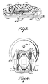
- Fig. 1 shows a refrigerator compressor motor system 10 including a conventional sealed compressor unit 12, a conventional motor protector means 14 such as that shown and described in U.S. Patent No. 4,706,152 incorporated herein by this reference and a conventional PTC motor starting means 16 such as that shown and described in U.S. Patent No. 4,241,370 incorporated herein by this reference.
- the sealed compressor unit incorporates a conventional electrical motor 18 and a refrigerator compressor 20 operated by the motor which are hermetically sealed in a common metal shell 22.
- the unit is mounted in any conventional manner in any refrigerator appliance, for example, as is diagrammatically illustrated at 24.
- Thermally and electrically conductive lead through pins 26.1, 26.2 and 26.3 (Fig. 2), electrically insulated from the shell and from each other by glass seal means 28 or the like, extend in sealed relation through the shell to make electrical connection to the windings of the electrical motor in the shell.
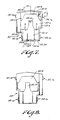
- Motor protector means 14 includes, as seen in Fig. 3, a housing 14.1 mounting a snap acting disc 14.2 formed of thermostat metal and is movable between opposite dished configurations in response to temperature.
- a movable contact arm 14.4 cantilever mounted at 14.6 has a movable electric contact 14.8 mounted on a free end thereof adapted to move into and out of electrical engagement with stationary contact 14.10 in response to the dished configuration of disc 14.2.
- An electrical resistance heater means 14.12 is electrically coupled to the motor circuit current to heat the thermostat disc. When the disc snaps to the configuration opposite to that shown in Fig. 3 it will bias the free end of arm 14.4 away from stationary contact 14.10 to interrupt the circuit.
- Resilient female socket means 14.14 is adapted to be received on pin 26.3 while terminal means 14.16 is adapted for connection to a separate electrical lead as will be explained below.
- Motor starter means 16 includes, as seen in Fig. 4, a housing 16.1 in which is disposed a positive temperature coefficient (PTC) of resistivity element 16.2.
- Contact means comprise resilient female socket means 16.3 and 16.4 attached to metal spring contacts 16.5 and 16.6 respectively engaging opposite sides of PTC element 16.2 and disposed between housing 16.1 and respective opposite sides of PTC element 16.2.
- Socket means 16.3 and 16.4 form lower terminals adapted to be placed in engagement with pins 26.1 and 26.2 respectively and are formed with upper terminals 16.7 and 16.8 respectively extending from the opposite side of housing 16.1 adapted to be connected to electric leads.
- Terminal 16.9 may commonly be used for the power connection in resistor start capacitor run (RSCR) applications.
- RSCR resistor start capacitor run
- components 14 and 16 are placed on pins 26.1, 26.2 and 26.3 as the compressor unit moves along an assembly line. Appropriate leads are then attached to terminals 14.16, 16.7, 16.8 and 16.9 and then a plastic cover is placed over both components and clipped to shell 22 to electrically isolate all electrical connections and provide protection from impact.
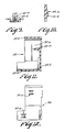
- a combination housing 30 as seen in Fig. 5 provides for one step on-line installation of the motor protector, motor starter components.
- Housing 30 comprises a first housing portion 32 which cooperates with a second housing portion 34 to provide a combination housing which permits off-line assembly of the motor protector and motor starter components and connection of appropriate electrical wires so that the combination can be installed on a compressor unit merely by pushing it onto the connector pins extending through the compressor unit shell.
- housing portion 32 comprises a bottom wall 32.2 with depending side wall 32.4 forming a recess 32.6 therein.
- a pin receiving aperture 32.8 generally in the shape of an inverted U is formed in the bottom wall to accommodate triangularly disposed pins 26.1, 26.2, 26.3 discussed supra.
- a leg 32.10 projects from the bottom wall 32.2 into recess 32.6 to separate the portions of the recess designated for the protector component from the starter component, to limit movement of the starter component and, most importantly, to prevent access to internal electrical connections by a foreign mumber such as a probe.
- a groove 32.12 is formed in the bottom wall to receive a complimentary shaped portion of the starter housing 16.1 and locating protrusions 32.14 are formed in opposite ends of side wall 32.4 to facilitate location of starter component 16 and protector component 14 as shown in Fig. 6.
- a plurality of snap attachment means 32.16 are formed on the outer surface of side wall 32.4, each providing a ledge portion 32.18 (see Fig. 10) adapted to lockingly receive a respective tongue portion of second housing portion 34 to be described below. It will be understood that other means of attachment, such as staking, could be employed if desired.
- lead receiving apertures in the form of slots 32.20, 32.22 and 32.24 are provided in side wall 32.2 at an end of housing portion 32.
- Second housing portion 34 comprises a top walls 34.2, 34.4, depending side wall 34.6 and legs 34.8. Tongues 34.10 attached to the distal end of legs 34.8 are adapted to slide over respective ledges 32.18 of the attachment means to effectively lock housing portion 32 and 34 together upon assembly.
- Downwardly depending protrusions 34.20, 34.22 and 34.24 extend from top wall 34.2 and are aligned with lead apertures 32.20, 32.22 and 32.24 respectively as will be discussed further below.
- Downwardly depending wall portions 32.26 extends from top wall 34.2 and is aligned with the starter component seat so that upon assembly a force exerted on the combination housing 30 can be transferred through to the pins when installing housing 30 on a compressor unit.
- wall 32.28 aligns with protector unit 14 for support.
- protector unit 14 is inserted in recess 32.6 and is relatively loosely held within the recess between upper protrusions 32.14 and leg 32.10. Starter unit 14 is inserted with very little play or movement, as seen in Fig. 6, in a direction toward protector unit 14. Insulated electric wires or leads are attached to protector terminal 14.16 and starter terminals 16.7, 16.8 and 16.9. Lead L14 attached to terminal 14.16 is directed through lead aperture 32.20, capacitor leads LC1 and LC2 are attached to terminal 16.7 and 16.8 and directed through apertures 32.22 and 32.24 respectively and lead L16 is attached to a second terminal 16.9 and directed through aperture 32.24.
- Second housing unit 34 which serves as a cover, is then placed over the recess and tongues 34.10 snapped over ledges 32.18 which results in protrusions 34.20, 34.22 and 34.24 engaging leads passing through the lead apertures thereby placing a force on the leads and providing strain relief to the internal electrical connections.
- Unit 30 is then supplied to the assembly line and is installed on a compressor unit in a single on-line operation by pushing the unit onto the connector pins extending through the compressor unit shell.
- the housing of protector 14 is provided with a tapered portion 14.20 adjacent to socket 14.4 (see Fig. 2) which serves as a self aligning mechanism when unit 30 is placed onto the pins; pin 26.3 will engage the tapered portion and automatically adjust the position of protector 14 in its seat as determined by the position of pins 26.1, 26.2.
- the combination housing by enclosing all live electrical connections, meets all electrical code requirements thereby obviating a need for a separate cover required by the prior art.
- the combination housing is configured to be universal with regard to fitting within the fence area of the compressors of various manufacturers.
Landscapes
- Compressor (AREA)
- Motor And Converter Starters (AREA)
Applications Claiming Priority (2)
| Application Number | Priority Date | Filing Date | Title |
|---|---|---|---|
| US288070 | 1988-12-22 | ||
| US07/288,070 US4862306A (en) | 1988-12-22 | 1988-12-22 | Combination motor protector and starter apparatus |
Publications (1)
| Publication Number | Publication Date |
|---|---|
| EP0375261A1 true EP0375261A1 (de) | 1990-06-27 |
Family
ID=23105618
Family Applications (1)
| Application Number | Title | Priority Date | Filing Date |
|---|---|---|---|
| EP89313032A Withdrawn EP0375261A1 (de) | 1988-12-22 | 1989-12-13 | Zusammengestellte Motorschutz- und Startervorrichtung |
Country Status (3)
| Country | Link |
|---|---|
| US (1) | US4862306A (de) |
| EP (1) | EP0375261A1 (de) |
| JP (1) | JP2799204B2 (de) |
Cited By (2)
| Publication number | Priority date | Publication date | Assignee | Title |
|---|---|---|---|---|
| GB2301714A (en) * | 1995-05-30 | 1996-12-11 | Gen Electric | Motor protector and starter module |
| WO2001013506A1 (de) * | 1999-08-12 | 2001-02-22 | Siemens Aktiengesellschaft | Kombination eines schützes mit einem sanftanlasser |
Families Citing this family (9)
| Publication number | Priority date | Publication date | Assignee | Title |
|---|---|---|---|---|
| US5170307A (en) * | 1991-05-31 | 1992-12-08 | Texas Instruments Incorporated | Mounting apparatus for electrical motor control components |
| BR9605552A (pt) * | 1996-11-13 | 1998-08-18 | Texas Instr Eletronicos Do Bra | Montagem de componentes de controle de motor elétrico |
| US6122154A (en) * | 1997-04-24 | 2000-09-19 | Damerow; Robert William | Motor starting device and protector module with motor starter cut-out switch |
| US6331742B1 (en) * | 1998-12-31 | 2001-12-18 | General Electric Company | Electric motor connector module |
| CN100407558C (zh) * | 2000-12-04 | 2008-07-30 | 巴西船用压缩机有限公司 | 电动马达启动系统的构建装置 |
| US6795283B2 (en) * | 2001-04-20 | 2004-09-21 | Texas Instruments Incorporated | Electricals package integrating run capacitor, motor protector and motor starter |
| KR100698762B1 (ko) * | 2004-11-16 | 2007-03-23 | 센서스앤드컨트롤스코리아 주식회사 | 냉장고 압축기용 접속 패키지 |
| ITPC20050006U1 (it) * | 2005-03-10 | 2006-09-11 | Electrica Srl | Rele' voltmetrico con base sagomata che presenta incavi atti a costituire sedi per l'inserimento di attacchi tipo "faston" |
| JP2013009585A (ja) * | 2011-06-23 | 2013-01-10 | Sensata Technologies Massachusetts Inc | 電動モータスタータ部品の組立 |
Citations (5)
| Publication number | Priority date | Publication date | Assignee | Title |
|---|---|---|---|---|
| US4299026A (en) * | 1978-11-14 | 1981-11-10 | Texas Instruments Incorporated | Method of assembling a motor starting relay |
| GB2086556A (en) * | 1980-11-03 | 1982-05-12 | Necchi Spa | Terminal box assembly on a refrigerator compressor unit |
| GB2104732A (en) * | 1981-08-07 | 1983-03-09 | Aspera Spa | Supply and protection unit for a hermetic compressor |
| EP0194892A2 (de) * | 1985-03-15 | 1986-09-17 | Texas Instruments Incorporated | Schutzsysteme für einen Kältemaschinenkompressormotor |
| DE3528141C1 (de) * | 1985-08-06 | 1987-01-22 | Danfoss As | PTC-Anlassvorrichtung fuer einen Asynchronmotor |
Family Cites Families (17)
| Publication number | Priority date | Publication date | Assignee | Title |
|---|---|---|---|---|
| US31367A (en) * | 1861-02-12 | Improvement in cultivators | ||
| US3718879A (en) * | 1971-05-19 | 1973-02-27 | Texas Instruments Inc | Apparatus for starting and protecting of electrical motors |
| US4037316A (en) * | 1974-09-23 | 1977-07-26 | General Electric Company | Method of assembling temperature responsive resistance member |
| US4042860A (en) * | 1975-10-21 | 1977-08-16 | General Electric Company | Combination starter-protector device |
| USRE31367E (en) | 1975-12-22 | 1983-08-30 | Texas Instruments Incorporated | Motor starting and protecting apparatus |
| US4131871A (en) * | 1977-01-24 | 1978-12-26 | General Electric Company | Electrical device and method |
| US4241370A (en) * | 1978-11-14 | 1980-12-23 | Texas Instruments Incorporated | Thermal relays particularly for starting single-phase asynchronous motors |
| US4237510A (en) * | 1978-12-29 | 1980-12-02 | Texas Instruments Incorporated | Electrical switching apparatus |
| US4334162A (en) * | 1980-03-17 | 1982-06-08 | General Electric Company | Releasable combination and method of assembly |
| US4319299A (en) * | 1980-04-23 | 1982-03-09 | General Electric Company | Combination starter-protector device, apparatus utilizing such device, and methods of assembling |
| US4422120A (en) * | 1980-10-13 | 1983-12-20 | Murata Manufacturing Co., Ltd. | Combination starter-protector device |
| US4493144A (en) * | 1980-10-31 | 1985-01-15 | General Electric Company | Method of assembling a combination starter-protector device |
| US4387412A (en) * | 1980-10-31 | 1983-06-07 | General Electric Company | Combination starter-protector device |
| IT1147234B (it) * | 1981-09-03 | 1986-11-19 | Necchi Spa | Gruppo rele' d'avviamento, morsetteria per motocompressori ermetici |
| JPS6135595A (ja) * | 1984-07-27 | 1986-02-20 | 株式会社日立製作所 | 電気品保護装置 |
| JPH0728142B2 (ja) * | 1984-07-27 | 1995-03-29 | 株式会社日立製作所 | 電気品保護装置 |
| JPS63220745A (ja) * | 1987-03-09 | 1988-09-14 | Matsushita Refrig Co | モ−タの起動・過負荷保護装置 |
-
1988
- 1988-12-22 US US07/288,070 patent/US4862306A/en not_active Expired - Fee Related
-
1989
- 1989-12-08 JP JP1317960A patent/JP2799204B2/ja not_active Expired - Fee Related
- 1989-12-13 EP EP89313032A patent/EP0375261A1/de not_active Withdrawn
Patent Citations (5)
| Publication number | Priority date | Publication date | Assignee | Title |
|---|---|---|---|---|
| US4299026A (en) * | 1978-11-14 | 1981-11-10 | Texas Instruments Incorporated | Method of assembling a motor starting relay |
| GB2086556A (en) * | 1980-11-03 | 1982-05-12 | Necchi Spa | Terminal box assembly on a refrigerator compressor unit |
| GB2104732A (en) * | 1981-08-07 | 1983-03-09 | Aspera Spa | Supply and protection unit for a hermetic compressor |
| EP0194892A2 (de) * | 1985-03-15 | 1986-09-17 | Texas Instruments Incorporated | Schutzsysteme für einen Kältemaschinenkompressormotor |
| DE3528141C1 (de) * | 1985-08-06 | 1987-01-22 | Danfoss As | PTC-Anlassvorrichtung fuer einen Asynchronmotor |
Cited By (5)
| Publication number | Priority date | Publication date | Assignee | Title |
|---|---|---|---|---|
| GB2301714A (en) * | 1995-05-30 | 1996-12-11 | Gen Electric | Motor protector and starter module |
| US5729416A (en) * | 1995-05-30 | 1998-03-17 | General Electric Company | Motor starter and protector module |
| GB2301714B (en) * | 1995-05-30 | 2000-03-08 | Gen Electric | Motor starter and protector module |
| WO2001013506A1 (de) * | 1999-08-12 | 2001-02-22 | Siemens Aktiengesellschaft | Kombination eines schützes mit einem sanftanlasser |
| US6531940B1 (en) | 1999-08-12 | 2003-03-11 | Siemens Aktiengesellschaft | Combined contactor/soft starter |
Also Published As
| Publication number | Publication date |
|---|---|
| JPH02202336A (ja) | 1990-08-10 |
| JP2799204B2 (ja) | 1998-09-17 |
| US4862306A (en) | 1989-08-29 |
Similar Documents
| Publication | Publication Date | Title |
|---|---|---|
| EP0104809B1 (de) | Motorschutzvorrichtung | |
| EP0090491A2 (de) | Kleinschutz für elektrische Schaltung | |
| EP0676786B1 (de) | Kompakte Schutzeinrichtung | |
| US4467385A (en) | Supply and protection unit for a hermetic compressor | |
| EP0177652B1 (de) | Motorschutz, insbesondere geeignet für Anwendung in Kompressormotoren | |
| US4995017A (en) | Safety power receptacle | |
| CA1131300A (en) | Combination starter-protector device | |
| US4499517A (en) | Motor protector particularly suited for use with compressor motors | |
| US4862306A (en) | Combination motor protector and starter apparatus | |
| EP0194892A2 (de) | Schutzsysteme für einen Kältemaschinenkompressormotor | |
| US7385473B2 (en) | One-shot heat sensing electrical receptacle | |
| US5170307A (en) | Mounting apparatus for electrical motor control components | |
| US4951025A (en) | Thermally monitored electrical outlet receptacle receptacle apparatus | |
| US5897055A (en) | Actuator with an electrically heatable thermostatic operating element | |
| JPS5848976B2 (ja) | 遅延リレ− | |
| EP0484077B1 (de) | Schutzvorrichtung für Kompressormotor | |
| GB1585497A (en) | Electrical devices with plug-in terminals | |
| US5864279A (en) | Temperature-dependent switch with a retaining bracket | |
| US4255736A (en) | Thermal protective switch | |
| US4458231A (en) | Protector apparatus for dynamoelectric machines | |
| US4164000A (en) | Relay-starter electrical device for a prime mover | |
| EP1072048B1 (de) | Verbesserung bezüglich einer temperaturregelung für elektrische heizelemente | |
| US4395694A (en) | Thermostat construction employing aramide insulation | |
| US3537052A (en) | Thermostat | |
| US4327481A (en) | Method of assembling an electrical device |
Legal Events
| Date | Code | Title | Description |
|---|---|---|---|
| PUAI | Public reference made under article 153(3) epc to a published international application that has entered the european phase |
Free format text: ORIGINAL CODE: 0009012 |
|
| AK | Designated contracting states |
Kind code of ref document: A1 Designated state(s): DE FR GB IT NL |
|
| STAA | Information on the status of an ep patent application or granted ep patent |
Free format text: STATUS: THE APPLICATION IS DEEMED TO BE WITHDRAWN |
|
| 18D | Application deemed to be withdrawn |
Effective date: 19901228 |