EP0375341A2 - Lampe à décharge à haute pression avec filament incandescent pour son allumage - Google Patents
Lampe à décharge à haute pression avec filament incandescent pour son allumage Download PDFInfo
- Publication number
- EP0375341A2 EP0375341A2 EP89313250A EP89313250A EP0375341A2 EP 0375341 A2 EP0375341 A2 EP 0375341A2 EP 89313250 A EP89313250 A EP 89313250A EP 89313250 A EP89313250 A EP 89313250A EP 0375341 A2 EP0375341 A2 EP 0375341A2
- Authority
- EP
- European Patent Office
- Prior art keywords
- arc tube
- filament
- arc
- tube assembly
- discharge
- Prior art date
- Legal status (The legal status is an assumption and is not a legal conclusion. Google has not performed a legal analysis and makes no representation as to the accuracy of the status listed.)
- Withdrawn
Links
Images

Classifications
-
- H—ELECTRICITY
- H01—ELECTRIC ELEMENTS
- H01J—ELECTRIC DISCHARGE TUBES OR DISCHARGE LAMPS
- H01J61/00—Gas-discharge or vapour-discharge lamps
- H01J61/82—Lamps with high-pressure unconstricted discharge having a cold pressure > 400 Torr
- H01J61/825—High-pressure sodium lamps
-
- H—ELECTRICITY
- H01—ELECTRIC ELEMENTS
- H01J—ELECTRIC DISCHARGE TUBES OR DISCHARGE LAMPS
- H01J61/00—Gas-discharge or vapour-discharge lamps
- H01J61/02—Details
- H01J61/54—Igniting arrangements, e.g. promoting ionisation for starting
- H01J61/545—Igniting arrangements, e.g. promoting ionisation for starting using an auxiliary electrode inside the vessel
Definitions
- This invention relates to high pressure arc discharge lamps and, more particularly, to high pressure sodium lamps which utilize an incandescent filament located within the arc tube for starting.
- HPS high pressure sodium
- the standard high pressure sodium (HPS) arc discharge lamp is a very efficient source of visible light and has among the highest efficacies (lumens per watt) of any commercially available lamp.
- HPS lamp has found only limited application, due in part to the special starting and ballasting requirements.
- a high voltage pulse on the order of 2000 volts is required for cold starting of prior art HPS lamps.
- Voltages as high as 10 kilovolts are required for hot restart.
- the starting and ballasting requirements do not deter use.
- a high pressure sodium discharge lamp having a multiple turn tungsten wire starting aid wound around the outside of the arc tube is disclosed in U.S. Patent No. 4,037,129 issued July 19, 1977 to Zack et al. During starting, the tungsten starting aid is connected to the same voltage as one of the arc tube electrodes.
- an arc tube assembly comprising a light-transmitting arc tube that encloses a discharge region and contains a fill material for supporting an arc discharge, a pair of electrodes sealed in the arc tube, and a filament located within the arc tube and extending between opposite ends thereof.
- the filament is electrically connected to the electrodes.
- the filament provides sufficent electric field and an abundance of electrons dispersed throughout the discharge region to initiate an arc discharge therein when the electrodes are energized.
- the arc tube is typically a high pressure sodium arc tube.
- the filament is designed to produce an electric field in the discharge region prior to initiation of arc discharge of at least 20 volts per centimeter.
- the filament simultaneously produces a well-distributed electric field, thermonic electrons and heating which are sufficient to rapidly inititate an arc discharge within the arc tube.
- the filament is a refractory metal such as tungsten. After an arc discharge is inititated, the voltage between the electrodes drops, and the filament is partially short-circuited by the arc discharge.
- the filament provides fast initial starting and fast hot restarting, while eliminating the requirement for high voltage starting pulses.
- the filament provides light during the interval between application of electrical power and initiation of an arc discharge.
- an arc tube assembly comprises a light-transmitting arc tube that encloses a discharge region and contains a fill material for supporting an arc discharge, a pair of electrodes sealed at opposite ends of the arc tube, and a resistive member located within the arc tube and extending between opposite ends thereof.
- the resistive member is electrically connected to the electrodes and provides sufficient electric field and electrons in the discharge region to initiate an arc discharge when the electrodes are energized.
- the resistive member can be a filament extending between the electrodes without touching the wall of the arc tube.
- the resistive member can be one or more resistive strips located on the inside surface of the arc tube, or can be a transparent coating on the inside surface of the arc tube.
- FIG. 1 A high pressure sodium arc tube assembly in accordance with the present invention is shown in FIG. 1.
- the assembly includes a light-transmitting ceramic arc tube 10, usually made of polycrystalline alumina.
- the arc tube 10 is a cylindrical shell that is closed on both ends to define a sealed discharge region 12.
- Electrodes 14 and 16 are positioned at opposite ends of arc tube 10 and are mounted on electrode feedthroughs 18 and 20, respectively.
- the feedthroughs 18 and 20 are typically niobium tubes which are sealed to the arc tube 10 and which provide means for energizing electrodes 14 and 16 from an external electrical source.
- the fill material inside arc tube 10 typically includes xenon gas plus mercury and sodium in the form of an amalgam.
- the arc tube assembly of FIG. 1 is typically incorporated into a conventional high pressure sodium lamp including a transparent outer envelope, a lamp base for mounting and for connection to an electrical source, mechanical means for mounting the arc tube in the outer envelope, and means for electrically connecting the electrodes 14 and 16 to the lamp base.
- a filament 24 is positioned within the arc tube 10 and is connected at opposite ends to electrodes 14 and 16.
- the filament 24 thus extends the length of the arc tube 10 and, in the embodiment of FIG. 1, is located approximately on the axis of arc tube 10.
- the filament 24 can be maintained in position and prevented from contacting the arc tube wall by one or more filament spacers 26 and by proper recrystallization of the tungsten.
- the filament 24 is a double-coiled or a triple-coiled tungsten wire. More generally, the filament 24 is any refractory material that can produce the required electric field as described hereinafter. Suitable materials in addition to tungsten include refractory metals such as tantalum, rhenium, molybdenum, and conductive ceramics.
- the filament 24 is electrically connected to electrodes 14 and 16. When a voltage is applied to the arc tube 10 between electrodes 14 and 16, the filament 24 lights up as an incandescent lamp.
- the filament 24 has three important effects which result in rapid formation of an arc discharge within the arc tube 10.
- the voltage applied across the filament 24 produces an electric field in the discharge region 12.
- the filament 24 parameters and the magnitude of the applied voltage should be selected to produce an axial electric field in the discharge region 12 of at least 20 volts per centimeter.
- the filament 24 also emits thermionic electrons which assist in the formation of an arc discharge.
- the heat released from the filament 24 warms the sodium amalgam in the arc tube 10 and rapidly causes the sodium/mercury to attain a high enough vapor pressure to form the desired arc discharge.
- the voltage between the electrodes 14 and 16 drops, causing a reduction in current through the filament 24.
- the sodium quickly overtakes the discharge because of its lower ionization potential compared to xenon and mercury, thus finishing the ignition process without the need for a high voltage starting pulse.
- the sodium is activated in just a few seconds.
- the required voltage across the filament 24 to effect starting is no greater than normal AC line voltage.
- the lamp shown in FIG. 1 can be started with an applied voltage below 120 volts AC. After initiation of a discharge, the voltage typically drops to about 60 volts. Thus, the requirement for a high voltage starting pulse generator is eliminated.
- the filament is designed for a starting voltage that is about twice the arc running voltage.
- the arc tube assembly of the present invention can be stabilized by a standard capacitive or inductive ballast.
- the typical tungsten filament must be light bulb grade tungsten capable of handling the starting current. Since the filament is not carrying substantial current except during startup, it is expected that the filament will last considerably longer than the filaments in incandescent light bulbs.
- the filament is designed to provide sufficient electric field along the axis of the arc tube 10 to ignite the sodium in the tube by acceleration of thermionic electrons. The ignition of mercury is not required. Xenon ignition can often precede ignition of sodium if the voltage is high enough and/or if the fill pressure is low enough. However, in the arc tube assembly of the present invention, ignition of xenon is not necessary for heating of the sodium, since the sodium is heated by the filament.
- the required electric field has been found experimentally to be between 20 volts per centimeter and 30 volts per centimeter to ignite the vapors thermionically.
- the filament which is typically double-coiled, must develop the required electric field along the axial direction of the tube 10 as it becomes incandescent. For example, a filament carrying 1.0 amp with a hot resistance of 60 ohms develops 60 volts. If the length of the filament is between 2 and 3 centimeters, then the electric field is between 20 and 30 volts per centimeter, and a discharge will be initiated. It will be understood that different combinations of voltages, filament resistances and filament lengths can be used to provide the required electric field.
- the electrode feedthrough 20 is typically a niobium tube.
- the electrode 16 is typically tungsten.
- the electrode 16 includes a cylindrical portion 16a attached to feedthrough 20 and a tapered portion 16b.
- the portion 16b tapers from the diameter of cylindrical portion 16a to a point and has a generally conical shape.
- the filament 24 is attached to the cylindrical portion 16a by crimping or an equivalent mechanical technique.
- the arc tube 10 is sealed with a polycrystalline alumina hat seal 28 through which the electrodes are inserted.
- the electrode feedthrough 20 is made of niobium tubing 0.123-inch in diameter, and the tungsten electrode 16 has a diameter of 0.045-inch.
- the filament is either attached directly to the electrode 16 by twisting or crimping, or it can be attached indirectly through an intermediate tungsten wire.
- FIG. 3 An alternate embodiment of the arc tube assembly in accordance with the present invention is shown in FIG. 3. Elements that are common with the arc tube assembly of FIG.1 have the same reference numerals.
- the arc tube 10 has electrode feedthroughs 18 and 20 mounted in opposite ends thereof. Electrodes 30 and 32 are mounted to feedthroughs 18 and 20, respectively. The electrodes 30 and 32 are conventional backwound, coated tungsten HPS electrodes. As shown in FIG. 4, electrode 32 includes a tungsten rod 34 attached to feedthrough 20. Tungsten coils 36, with a typical coating consisting of barium carbonate, calcium carbonate and yttrium oxide, are wound around rod 34. Coatings on coil 36 are used to enhance electron emission independent of the sodium presence.
- a filament 40 is located within arc tube 10 and extends between electrodes 30 and 32. Because the ends of electrodes 30 and 32 are enlarged, it is most practical to connect the ends of the filament 40 to each electrode near the point of intersection between the electrode rod and the respective feedthrough 20, as best shown in FIG. 4. This causes the filament 40 to be somewhat offset from the axis of the tube 10. Preferably, the filament 40 is connected to radially opposite sides of the respective electrodes 30 and 32 so that it runs at a small angle to the tube axis, as shown in FIG. 3. A spacer 42 prevents the center portion of the filament 40 from contacting the wall of the arc tube 10.
- the filament 40 can be constructed generally in the same manner as the filament 24 shown in FIG. 1 and described hereinabove.
- the arc heating depletes sodium from the ends of the filament where the current now concentrates, the arc will be starved of electrons and the lamp will return to its incandescent mode. When the ends are cool enough to redeposit sodium and thus reestablish the required supply of electrons, the arc will be reinitiated. The on/off cycling can continue if proper design precautions are not taken. It is important to thermally design the electrode ends of the arc so that an equilibrium point is established at which sufficient heating and sodium coating coexist on the surface for the required thermionic emission to be available. Furthermore, the ends of the arc tube must be thermally insulated so that the sodium supply is hot enough to maintain the surface coverage on the tungsten and the vapor density for the arc. Typically, conventional 10 millimeter heat shields with ceramic insulation on the arc tube ends are used.
- the electrode 16 terminates in the shape of a cone.
- the cone is positioned in the region of the filament 24 so that it protrudes into the arc.
- the arc ends seek the axial location on the cone at which the heating and the thermionic electrons match. At this temperature and surface area, the arc footpoints are not starved of current and the surface conditions are stable. Stability is assured with the activator producing emitter cathode system shown in FIGS. 3 and 4.
- Lamps have been constructed in accordance with the embodiments of FIGS. 1 and 3.
- the lamps with cone-shaped electrodes, as shown in FIGS. 1 and 2 exhibited practically instaneous hot restart.
- the fully-stabilized arc lamps provided 50 lumens per watt.
- Lamps having conventional HPS electrodes as shown in FIGS. 3 and 4 exhibited practically instanteous hot restart.
- the fully-stabilized arc lamps provided 60 lumens per watt. In both cases, arc ignition on cold start is too fast to measure without special instrumentation, and two to three minutes are required to fully stabilize the arc after cold start.
- the filament for initiating discharge is replaced with one or more resistive strips located on the inside surface of the polycrystalline alumina arc tube.
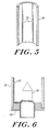
- a cross-sectional view of an arc tube 50 is shown in FIG. 5.
- One or more resistive strips 52 are applied to the inside surface of the arc tube and are connected to the electrodes at both ends of the arc tube. As shown in FIG. 6, the strips 52 extend across hat seal 54 and are attached to electrode 56. Preferably, several strips 52 are utilized at spaced-apart locations on the wall of arc tube 50.
- the strips 52 perform the same function as the filaments 24 and 40 described hereinabove by developing an electric field within the arc tube and supplying thermionic electrons.
- the strips 52 must be narrow to minimize light blockage and must have a resistance selected to produce the required electric field of 20 volts per centimeter to 30 volts per centimeter when the specified starting voltage is applied to the electrodes.
- the material of the strips 52 must be compatible with the hot alumina and the discharge constituents. Refractory metals such as niobium and molybdenum, and conductive ceramics are suitable materials. Techniques such as plasma spraying, electroless plating and metallizing plating are suitable techniques for applying the strips 52 to the arc tube wall. According to a variation of the configuration shown in FIGS. 5 and 6, the entire inside surface of arc tube 50 is coated with a transparent material which provides the required starting function without substantially reducing the lumen output from the arc tube.
- the present invention has been described thus far in connection with high pressure sodium lamps. It is well known that metal halide arc discharge lamps require high voltages or other starting devices to initiate discharge.
- the present invention can be utilized in metal halide lamps to effect starting.
- a filament or other resistive member having a resistance selected to produce the required electric field for starting is connected between the electrodes of the metal halide arc tube.
- the arc tube assembly in accordance with the present invention provides numerous advantages over prior art arc tube configurations.
- the need for high voltage pulses to start high pressure sodium lamps is eliminated.
- the filament arc tube of the present invention permits the use of line voltages at available frequencies for lamp starting. Therefore, the hardware associated with high voltage starting can be eliminated, and there is no disturbance to the power line from the high voltage starting pulses.
- the elimination of high voltage starting transients is particularly important, for example, when a large number of street lights are started at once.
- the filament arc tube of the present invention provides faster cold starting and faster hot restarting than prior art HPS lamps. Furthermore, arc reignition is smoother than in conventional lamps. In addition, light is produced the moment power is applied.
- the incandescent filament lights up almost instantaneously when the arc is not on and goes out when the arc is on.
- the filament arc tube of the invention permits different xenon fill pressures than in prior art high pressure sodium lamps because xenon is not required to assist in starting.
Landscapes
- Discharge Lamps And Accessories Thereof (AREA)
- Vessels And Coating Films For Discharge Lamps (AREA)
Applications Claiming Priority (2)
| Application Number | Priority Date | Filing Date | Title |
|---|---|---|---|
| US287311 | 1988-12-20 | ||
| US07/287,311 US4939417A (en) | 1988-12-20 | 1988-12-20 | High pressure discharge lamp with incandescent filament for starting |
Publications (2)
| Publication Number | Publication Date |
|---|---|
| EP0375341A2 true EP0375341A2 (fr) | 1990-06-27 |
| EP0375341A3 EP0375341A3 (fr) | 1991-03-27 |
Family
ID=23102347
Family Applications (1)
| Application Number | Title | Priority Date | Filing Date |
|---|---|---|---|
| EP19890313250 Withdrawn EP0375341A3 (fr) | 1988-12-20 | 1989-12-19 | Lampe à décharge à haute pression avec filament incandescent pour son allumage |
Country Status (4)
| Country | Link |
|---|---|
| US (1) | US4939417A (fr) |
| EP (1) | EP0375341A3 (fr) |
| JP (1) | JPH02236947A (fr) |
| CA (1) | CA2005582C (fr) |
Families Citing this family (2)
| Publication number | Priority date | Publication date | Assignee | Title |
|---|---|---|---|---|
| US5066892A (en) * | 1990-12-07 | 1991-11-19 | Gte Products Corporation | Glow discharge lamp with incandescent filament |
| US5949192A (en) * | 1996-08-21 | 1999-09-07 | Matsushita Electric Industrial Co., Ltd. | Operating apparatus for discharge lamp |
Family Cites Families (8)
| Publication number | Priority date | Publication date | Assignee | Title |
|---|---|---|---|---|
| DE56658C (de) * | Ch. PÖLEKE in Ballenstedt a. Harz | Vorrichtung zum selbstthätigen Abmessen von gröfseren Flüssigkeitsmengen | ||
| US1006333A (en) * | 1903-02-14 | 1911-10-17 | Gen Electric | Vapor electric lamp. |
| NL36524C (fr) * | 1931-05-19 | |||
| US2094848A (en) * | 1934-09-11 | 1937-10-05 | Gen Electric | Gaseous and vapor electric discharge device |
| CH300409A (de) * | 1949-08-22 | 1954-07-31 | Patent Treuhand Ges Fuer Elektrische Gluehlampen Mbh | Elektrische Hochdruckgasentladungslampe mit festen Glühelektroden. |
| DE2424294A1 (de) * | 1973-05-25 | 1974-12-19 | Itt Ind Gmbh Deutsche | Natriumdampf-hochdruckentladungslampe und verfahren zur herstellung |
| GB1533345A (en) * | 1977-05-12 | 1978-11-22 | Gen Electric Co Ltd | High pressure electric discharge lamps |
| GB2120006B (en) * | 1982-05-07 | 1985-10-09 | Gen Electric Plc | Diversion of heat and light from ribbon seals in high-power electric lamps |
-
1988
- 1988-12-20 US US07/287,311 patent/US4939417A/en not_active Expired - Fee Related
-
1989
- 1989-12-14 CA CA002005582A patent/CA2005582C/fr not_active Expired - Fee Related
- 1989-12-19 EP EP19890313250 patent/EP0375341A3/fr not_active Withdrawn
- 1989-12-20 JP JP1328535A patent/JPH02236947A/ja active Pending
Also Published As
| Publication number | Publication date |
|---|---|
| CA2005582C (fr) | 1994-05-10 |
| US4939417A (en) | 1990-07-03 |
| JPH02236947A (ja) | 1990-09-19 |
| EP0375341A3 (fr) | 1991-03-27 |
| CA2005582A1 (fr) | 1990-06-20 |
Similar Documents
| Publication | Publication Date | Title |
|---|---|---|
| US4093893A (en) | Short arc fluorescent lamp | |
| US4353007A (en) | Discharge lamp unit including integral ballast | |
| US5661367A (en) | High pressure series arc discharge lamp construction with simplified starting aid | |
| US4117374A (en) | Fluorescent lamp with opposing inversere cone electrodes | |
| EP0313027A2 (fr) | Lampe à décharge à arc renfermant une source d'amorçage à radiation ultraviolette | |
| JP2003514366A (ja) | 一体化したuvエンハンサーを有するセラミックのメタルハライドランプ | |
| US4105908A (en) | Metal halide lamp having open tungsten coil electrodes | |
| CN1151540C (zh) | 金属卤化物灯 | |
| EP0098014B1 (fr) | Lampe à décharge à sodium à haute pression avec emploi d'une spirale de métal à potentiel positif | |
| US5336968A (en) | DC operated sodium vapor lamp | |
| US3828214A (en) | Plasma enshrouded electric discharge device | |
| US4939417A (en) | High pressure discharge lamp with incandescent filament for starting | |
| JP2003517710A (ja) | 高圧放電ランプ | |
| US3356884A (en) | Electrode starting arrangement having a coiled heating element connected to the retroverted portion of the electrode | |
| JP2003513428A (ja) | 照明システム | |
| US20060238127A1 (en) | High-pressure discharge lamp | |
| GB2073944A (en) | High pressure discharge lamp | |
| US4910433A (en) | Emitterless SDN electrode | |
| US3634718A (en) | High-pressure gaseous discharge lamp including a starting electrode | |
| US3849699A (en) | Single base, self-igniting fluorescent lamp | |
| US3215881A (en) | Start-run plural cathode structure | |
| GB2079044A (en) | Fluorescent lighting system | |
| US5218269A (en) | Negative glow discharge lamp having wire anode | |
| EP0517304A2 (fr) | Lampe de décharge de gaz à haute pression | |
| WO2006028112A1 (fr) | Lampe a halogenure metallique et dispositif d'eclairage utilisant celle-ci |
Legal Events
| Date | Code | Title | Description |
|---|---|---|---|
| PUAI | Public reference made under article 153(3) epc to a published international application that has entered the european phase |
Free format text: ORIGINAL CODE: 0009012 |
|
| AK | Designated contracting states |
Kind code of ref document: A2 Designated state(s): BE DE FR GB NL |
|
| PUAL | Search report despatched |
Free format text: ORIGINAL CODE: 0009013 |
|
| AK | Designated contracting states |
Kind code of ref document: A3 Designated state(s): BE DE FR GB NL |
|
| 17P | Request for examination filed |
Effective date: 19910917 |
|
| 17Q | First examination report despatched |
Effective date: 19930730 |
|
| STAA | Information on the status of an ep patent application or granted ep patent |
Free format text: STATUS: THE APPLICATION IS DEEMED TO BE WITHDRAWN |
|
| 18D | Application deemed to be withdrawn |
Effective date: 19931210 |