EP0375362B1 - Crochet pour la fixation de tuiles - Google Patents
Crochet pour la fixation de tuiles Download PDFInfo
- Publication number
- EP0375362B1 EP0375362B1 EP89313283A EP89313283A EP0375362B1 EP 0375362 B1 EP0375362 B1 EP 0375362B1 EP 89313283 A EP89313283 A EP 89313283A EP 89313283 A EP89313283 A EP 89313283A EP 0375362 B1 EP0375362 B1 EP 0375362B1
- Authority
- EP
- European Patent Office
- Prior art keywords
- tile
- tiles
- clip
- batten
- roof
- Prior art date
- Legal status (The legal status is an assumption and is not a legal conclusion. Google has not performed a legal analysis and makes no representation as to the accuracy of the status listed.)
- Expired - Lifetime
Links
Images


Classifications
-
- E—FIXED CONSTRUCTIONS
- E04—BUILDING
- E04D—ROOF COVERINGS; SKY-LIGHTS; GUTTERS; ROOF-WORKING TOOLS
- E04D1/00—Roof covering by making use of tiles, slates, shingles, or other small roofing elements
- E04D1/34—Fastenings for attaching roof-covering elements to the supporting elements
-
- E—FIXED CONSTRUCTIONS
- E04—BUILDING
- E04D—ROOF COVERINGS; SKY-LIGHTS; GUTTERS; ROOF-WORKING TOOLS
- E04D1/00—Roof covering by making use of tiles, slates, shingles, or other small roofing elements
- E04D1/29—Means for connecting or fastening adjacent roofing elements
- E04D1/2907—Means for connecting or fastening adjacent roofing elements by interfitted sections
- E04D1/2914—Means for connecting or fastening adjacent roofing elements by interfitted sections having fastening means or anchors at juncture of adjacent roofing elements
- E04D1/2916—Means for connecting or fastening adjacent roofing elements by interfitted sections having fastening means or anchors at juncture of adjacent roofing elements the fastening means taking hold directly on adjacent elements of the same row
-
- E—FIXED CONSTRUCTIONS
- E04—BUILDING
- E04D—ROOF COVERINGS; SKY-LIGHTS; GUTTERS; ROOF-WORKING TOOLS
- E04D1/00—Roof covering by making use of tiles, slates, shingles, or other small roofing elements
- E04D1/34—Fastenings for attaching roof-covering elements to the supporting elements
- E04D2001/3408—Fastenings for attaching roof-covering elements to the supporting elements characterised by the fastener type or material
- E04D2001/3411—Metal wires or rods
-
- E—FIXED CONSTRUCTIONS
- E04—BUILDING
- E04D—ROOF COVERINGS; SKY-LIGHTS; GUTTERS; ROOF-WORKING TOOLS
- E04D1/00—Roof covering by making use of tiles, slates, shingles, or other small roofing elements
- E04D1/34—Fastenings for attaching roof-covering elements to the supporting elements
- E04D2001/3452—Fastenings for attaching roof-covering elements to the supporting elements characterised by the location of the fastening means
- E04D2001/3458—Fastenings for attaching roof-covering elements to the supporting elements characterised by the location of the fastening means on the upper or lower transverse edges of the roof covering elements
-
- E—FIXED CONSTRUCTIONS
- E04—BUILDING
- E04D—ROOF COVERINGS; SKY-LIGHTS; GUTTERS; ROOF-WORKING TOOLS
- E04D1/00—Roof covering by making use of tiles, slates, shingles, or other small roofing elements
- E04D1/34—Fastenings for attaching roof-covering elements to the supporting elements
- E04D2001/3452—Fastenings for attaching roof-covering elements to the supporting elements characterised by the location of the fastening means
- E04D2001/3461—Fastenings for attaching roof-covering elements to the supporting elements characterised by the location of the fastening means on the lateral edges of the roof covering elements
-
- E—FIXED CONSTRUCTIONS
- E04—BUILDING
- E04D—ROOF COVERINGS; SKY-LIGHTS; GUTTERS; ROOF-WORKING TOOLS
- E04D1/00—Roof covering by making use of tiles, slates, shingles, or other small roofing elements
- E04D1/34—Fastenings for attaching roof-covering elements to the supporting elements
- E04D2001/347—Fastenings for attaching roof-covering elements to the supporting elements characterised by the fastening pattern
- E04D2001/3473—Fastenings for attaching roof-covering elements to the supporting elements characterised by the fastening pattern fastening single roof elements to the roof structure with or without indirect clamping of neighbouring roof covering elements
Definitions
- This invention relates to a clip for fixing a roof tile on a pitched roof.
- the clip is of particular use in the fixing of a replacement tile in a system where the tiles have interlocking regions along their lateral edges.
- an interlocking region of one tile overlaps an interlocking region of an adjacent tile and a ridge extending along one interlocking region engages in a channel extending along the other.
- a pitched roof using such interlocking tiles conventionally comprises rows of laterally interlocked tiles, with the rows overlapping down the roof.
- the joins between adjacent tiles will be aligned in the various rows up the roof.
- Each tile normally has a transverse rib on its underside adjacent its upper end, which engages over a batten on the roof.
- a clip to hold the lower end of a tile down, and in so doing to keep down the upper end of the tile in the next row down the roof.
- Such a clip can be secured to a roof batten in a suitable manner, and can engage in the interlocking channel of the upper tile.
- Such an arrangement is shown in e.g. GB 1, 174, 891 and GB 2,101,172.
- Another problem is that clips used to locate tiles can be unsightly and detract from the appearance of a roof.
- a further problem is that some clips have portions that underlie a tile in such a way that their size must be restricted or the laying of the tiles will be disturbed.
- the clip in GB-1174891 has a portion which lies on the upper surface of the batten, on which the tiles rest. This limits the diameter of the wire from which the clip is made, if it is not to interfere unduly with the laying of the tiles in an even fashion.
- a tile clip for a pitched roof of tiles for restraining a tile against movement away from, and movement down, the roof, the clip being secured to a roof batten adjacent the lower end of the said tile, on which batten rest tiles in a row below the row containing the tile, being overlapped by the said tile;
- the clip comprises first, second and third portions; the first portion being securable to the batten, without removing the tiles resting thereon, and extending up to the end of such tiles; the second portion extending upwardly from the first portion to the upper surface of the tiles resting on the batten; the third portion being straight and extending longitudinally from the second portion down the tiles resting on the batten, and wherein the third portion terminates in a hook having a first part which extends upwardly from the end of the third portion and a second part which extends parallel to the third portion so as to hook over the lower end of the tile.
- the tile clip is for use with tiles which interlock laterally in an arrangement in which the third portion of the clip extends along the join between the tile and a tile laterally adjacent thereto, and in that the first part of the hook also extends laterally from the end of the third portion so that the second part of the hook will extend into the interlocking region of said tile and the laterally adjacent tile.
- the tile is held in place but the only part of the clip visible is the part of the hook extending over the end of the tile.
- the rest of the hook is concealed in the interlocking region.
- the clip portion extending down the roof underneath the tile to be fixed extends along the join between that tile and the adjacent tile.
- This front join region conventionally is open somewhat along the undersurface of the tiles. This means that the clip can be made of wire or the like of relatively large diameter without disturbing the even laying of the tiles; the wire can be wholly or partially received in the gap along the join.
- the portion to be secured to the batten can simply have an end sharpened or otherwise adapted to be driven into the batten by hammering or the like. Normally, easy access to the batten will be impeded by the nibs of the tiles but this will not be the case in the region of the join between tiles.
- the clip in a roof where the joins of adjacent rows are aligned, the clip will generally have the first, second and third portions all lying in a plane containing a line of joins extending up the roof. Thus, these three portions will form a "U" shape although the third portion will generally be longer than the first portion.
- the hook can comprise a first part which extends perpendicularly to the axis of the third portion but at an angle to the plane of the three portions, and a second part which extends parallel the said plane.
- the angle can be, say, 45 degrees.
- the clip can be made from suitably stout steel wire or the like, to withstand being hammered into the batten and to restrain the tile in the event of strong winds.
- the clip is of particular use in the securing of a replacement tile which does not have a nib at its upper end but it will be of use in other contexts.
- the invention extends also to a pitched roof having interlocked tiles, at least one of which is secured by a clip as above described.
- the clip 1 is of generally "U" shaped configuration and is bent from suitable steel wire. It has a first portion 2 with a pointed end 3 adapted to be driven into a wooden tiling batten; a second portion 4 at right angles to portion 2; and a third portion 5 is parallel to portion 2 which is slightly longer than portion 2. These three portions lie in the same plane. At the end of third portion 5 is a hook portion 6 which has a part 7 extending away from the plane of portions 2, 4, and 5 at an angle of 45°, as can be seen from Figure 2, and a part 8 extending back parallel to portions 2 and 5.
- FIG 3 there is shown a roof of tiles 9 which have an undulating profile. These are laid in rows, with each row overlapping the row below.
- the tiles 9 in a row are interlocked along their edges, by means of an upper interlocking portion 10 having ridges and channels engaging with a lower interlocking portion 11, having corresponding ridges and channels, each tile 9 having an upper interlocking portion 10 along one edge and a lower interlocking portion 11 along the other edge.
- Each tile has a conventional nib 12 on its underside (not shown) which engages over a tiling batten as indicated diagramatically by broken lines at 13. Conventional clips can be used to restrain the tiles 9.
- a replacement tile to occupy the space marked as 14 must interlock with the tiles on either side and must lie under the tile in the row above. It will be seen that the tiles are aligned, so that the join 15 between two adjacent tiles in one row is aligned with the join in the rows above and below. As can be seen in Fgure 3, the design of the tiles is such that where two adjacent tiles are joined, as at 15, a space or groove 16 is defined along the underside of the tiles.
- the replacement tile to occupy space 16 will have no nib, so that it will not unduly disturb the tile in the overlapping row above; It must be held against sliding down the roof, and against movement away from the roof. This is done by means of the clip 1.
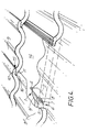
- the clip 1 is hammered into the roof batten in the region of the join 15 between the tiles.
- Portion 5 extends along the top of a tile 9′ in the row below the space 14, along the line of the groove 16 that will be formed at the join between the tile 9 ⁇ to the left of the space 14, and the replacement tile to be pushed into space 15.
- the clip is driven into the batten so that the end of portion 5 is at the overlap position.
- FIG. 5 shows a replacement tile 17 in place. As can be seen, only the small part 7 of clip 1 is visible. This part restrains the tile 17 from sliding down the roof, whilst part 8 holds the tile 17 down.
Landscapes
- Engineering & Computer Science (AREA)
- Mechanical Engineering (AREA)
- Architecture (AREA)
- Civil Engineering (AREA)
- Structural Engineering (AREA)
- Roof Covering Using Slabs Or Stiff Sheets (AREA)
- Buildings Adapted To Withstand Abnormal External Influences (AREA)
- Finishing Walls (AREA)
- Joining Of Building Structures In Genera (AREA)
- Geophysics And Detection Of Objects (AREA)
- Surgical Instruments (AREA)
- Burglar Alarm Systems (AREA)
- Vehicle Interior And Exterior Ornaments, Soundproofing, And Insulation (AREA)
- Saccharide Compounds (AREA)
Claims (5)
- Crochet pour tuile pour un toit incliné de tuiles (3) en vue de retenir une tuile (17) contre tout échappement et mouvement descendant du toit, le crochet (1) étant fixé à un liteau (13) adjacent à l'extrémité inférieure de la dite tuile (17), sur lequel liteau (13) reposent les tuiles (9') en une rangée au-dessous de la rangée contenant la tuile (17), qui sont chevauchées par la dite tuile (17); dans lequel le crochet (1) comprend des première (2), deuxième (4) et troisième (5) zones; la première zone (2) étant fixable au liteau (13) sans ôter les tuiles (9') reposant dessus, et s'étendant jusqu'à l'extrémité de telles tuiles (9'); la deuxième zone (4) faisant saillie au-dessus de la première zone (2) jusqu'à la surface supérieure des tuiles (9') reposant sur le liteau (13); la troisième zone (5) étant rectiligne et s'étendant longitudinalement à partir de la deuxième zone (4) au bas des tuiles (9') reposant sur le liteau (13), et dans lequel la troisième zone (5) se termine en forme de griffe (6) ayant une première partie (7) qui fait saillie vers le haut à partir de l'extrémité de la troisième zone (5) et une deuxième partie (8) qui fait saillie parallèlement à la troisième zone (5), de manière à s'accrocher au-dessus de l'extrémité inférieure de la tuile (17), caractérisé en ce que le crochet (1) est à utiliser avec des tuiles qui se verrouillent latéralement dans un arrangement selon lequel la troisième zone (5) du crochet s'étend le long de la jointure entre la tuile (17) et une tuile (9'') qui lui est latéralement adjacente, et en ce que la première partie (7) de la griffe (6) fait saillie également de l'extrémité de la troisième zone (5), de manière que la deuxième partie (8) de la griffe s'étende dans la région de verrouillage (10, 11) de la tuile (17) et de la tuile (9'') qui lui est latéralement adjacente.
- Crochet pour tuile selon la revendication 1 dans lequel les première, deuxième et troisième zones (2, 4, 5) reposent toutes dans un plan unique et affectent une forme générale en U, la troisième zone (5) étant plus longue que la dite première zone (2).
- Crochet pour tuile selon la revendication 2 dans lequel la dite zone en griffe (6) comprend une première partie (7) qui s'étend perpendiculairement à l'axe de la troisième zone (5), mais fait un angle par rapport au plan contenant les première, deuxième et troisième zones (2, 4, 5), et une deuxième partie (8) qui s'étend parallèlement au dit plan.
- Crochet pour tuile selon la revendication 3 dans lequel le dit angle est de 45°.
- Toit incliné comprenant des rangées de tuiles se verrouillant latéralement (9) au contact de liteaux latéraux de toit, les tuiles (9) en une rangée chevauchant les tuiles (9) dans une rangée adjacente inférieure du toit, dans lequel au moins une telle tuile est fixée à un liteau au moyen d'un crochet pour tuile tel que revendiqué dans n'importe quelle revendication précédente.
Applications Claiming Priority (2)
| Application Number | Priority Date | Filing Date | Title |
|---|---|---|---|
| GB888829600A GB8829600D0 (en) | 1988-12-19 | 1988-12-19 | Roof tile fixing clip |
| GB8829600 | 1988-12-19 |
Publications (2)
| Publication Number | Publication Date |
|---|---|
| EP0375362A1 EP0375362A1 (fr) | 1990-06-27 |
| EP0375362B1 true EP0375362B1 (fr) | 1994-08-03 |
Family
ID=10648739
Family Applications (1)
| Application Number | Title | Priority Date | Filing Date |
|---|---|---|---|
| EP89313283A Expired - Lifetime EP0375362B1 (fr) | 1988-12-19 | 1989-12-19 | Crochet pour la fixation de tuiles |
Country Status (9)
| Country | Link |
|---|---|
| US (1) | US5079889A (fr) |
| EP (1) | EP0375362B1 (fr) |
| AT (1) | ATE109538T1 (fr) |
| CA (1) | CA2005824A1 (fr) |
| DE (1) | DE68917276T2 (fr) |
| DK (1) | DK640789A (fr) |
| FI (1) | FI896081A7 (fr) |
| GB (1) | GB8829600D0 (fr) |
| IE (1) | IE64982B1 (fr) |
Families Citing this family (13)
| Publication number | Priority date | Publication date | Assignee | Title |
|---|---|---|---|---|
| US5921045A (en) * | 1995-03-23 | 1999-07-13 | Newport Fastener Company | Tile roof construction |
| DE19854771C1 (de) * | 1998-11-27 | 2000-02-17 | Ossenberg Schule & Soehne | Vorrichtung zur Befestigung von Dacheindeckungsteilen an der Lattung eines Daches |
| AUPQ013499A0 (en) * | 1999-05-03 | 1999-05-27 | Nu-Lok Roofing Systems Pty Ltd | Securing and weatherproofing roof tiles |
| ITBO20030625A1 (it) * | 2003-10-23 | 2005-04-24 | Gambale Srl | "coppo con maggiore capacita' di tenuta pluviale ed eolica". |
| US7444792B2 (en) * | 2005-02-10 | 2008-11-04 | M&O Products, Inc. | H clip |
| WO2007044775A1 (fr) * | 2005-10-07 | 2007-04-19 | Damon Stone | Systeme de carreaux en beton et son procede de fabrication |
| JP6216613B2 (ja) * | 2013-11-05 | 2017-10-18 | 株式会社鶴弥 | 瓦保持方法及び瓦保持クリップ |
| US9976778B2 (en) * | 2014-10-13 | 2018-05-22 | Solarcity Corporation | Integrated hook and flashing for photovoltaic module installation on tile roofs |
| US9322174B1 (en) * | 2015-02-12 | 2016-04-26 | John M. Williams | Roofing tile fastener and locking system |
| USD867122S1 (en) * | 2018-05-03 | 2019-11-19 | Israel Jimenez | Roof tile clip |
| US11598100B1 (en) | 2021-09-10 | 2023-03-07 | Vicki Lepior | Roof sheath connecting apparatus and associated method of use |
| USD1065609S1 (en) | 2022-06-09 | 2025-03-04 | Vicki Lepior | Roof sheathing connector |
| USD1048471S1 (en) | 2022-06-09 | 2024-10-22 | Pat Lepior | Roof sheathing connector |
Family Cites Families (8)
| Publication number | Priority date | Publication date | Assignee | Title |
|---|---|---|---|---|
| US757285A (en) * | 1903-10-21 | 1904-04-12 | Paul Duchemin | Support for slates or tiles on roofs. |
| GB191313818A (en) * | 1912-06-14 | 1914-03-12 | Charles Pierre Durand | Improvements in Hooks for Securing Roofing Tiles. |
| US1579715A (en) * | 1923-02-09 | 1926-04-06 | Shingle Lock Company | Shingle clip |
| GB308428A (en) * | 1928-02-20 | 1929-03-28 | William Small | Improvements in or relating to roofing tiles |
| GB1174891A (en) * | 1965-10-05 | 1969-12-17 | Redland Tiles Ltd | Improvements in or relating to the Securing of Roofing Tiles on a Roof |
| AU495578B2 (en) * | 1973-05-31 | 1975-12-04 | Vincent Higgins John | Tile holding device |
| AU520403B2 (en) * | 1979-07-03 | 1982-01-28 | Monier Colourtile Pty. Ltd. | Tile clip |
| GB2101172B (en) * | 1981-07-07 | 1985-08-21 | Marley Tile Company Limited Th | Tile clips |
-
1988
- 1988-12-19 GB GB888829600A patent/GB8829600D0/en active Pending
-
1989
- 1989-12-18 DK DK640789A patent/DK640789A/da not_active Application Discontinuation
- 1989-12-18 CA CA002005824A patent/CA2005824A1/fr not_active Abandoned
- 1989-12-18 IE IE406189A patent/IE64982B1/en not_active IP Right Cessation
- 1989-12-19 US US07/452,310 patent/US5079889A/en not_active Expired - Fee Related
- 1989-12-19 DE DE68917276T patent/DE68917276T2/de not_active Expired - Fee Related
- 1989-12-19 AT AT89313283T patent/ATE109538T1/de not_active IP Right Cessation
- 1989-12-19 EP EP89313283A patent/EP0375362B1/fr not_active Expired - Lifetime
- 1989-12-19 FI FI896081A patent/FI896081A7/fi not_active IP Right Cessation
Also Published As
| Publication number | Publication date |
|---|---|
| FI896081A0 (fi) | 1989-12-19 |
| DE68917276D1 (de) | 1994-09-08 |
| DE68917276T2 (de) | 1995-03-23 |
| GB8829600D0 (en) | 1989-02-08 |
| FI896081A7 (fi) | 1990-06-20 |
| IE64982B1 (en) | 1995-09-20 |
| ATE109538T1 (de) | 1994-08-15 |
| DK640789A (da) | 1990-06-20 |
| DK640789D0 (da) | 1989-12-18 |
| CA2005824A1 (fr) | 1990-06-19 |
| US5079889A (en) | 1992-01-14 |
| EP0375362A1 (fr) | 1990-06-27 |
Similar Documents
| Publication | Publication Date | Title |
|---|---|---|
| EP0375362B1 (fr) | Crochet pour la fixation de tuiles | |
| US4876827A (en) | Gutter assembly | |
| EP0710314B1 (fr) | Ameliorations apportees a un assemblage de toiture par bardeaux | |
| US5077952A (en) | Roof tile clip | |
| US2365845A (en) | Roof gutter protecting device | |
| US4322924A (en) | Roof ridge capping | |
| US4648218A (en) | Interlocking roof edge fascia system | |
| GB2101172A (en) | Tile clips | |
| US20040148898A1 (en) | Weather strips | |
| US4716701A (en) | Roof system based on two tile elements having means of attachment | |
| US4239414A (en) | Bracket for attaching rails to steel fence posts | |
| US20080236087A1 (en) | Weather strips | |
| US1648692A (en) | Roofing shingle | |
| US5542226A (en) | Roofer's grid apparatus | |
| EP0040619B1 (fr) | Organe de rive pour toit a deux pans et systeme de couverture pour toitures utilisant celui-ci | |
| US4442641A (en) | Verge member for a pitched roof and roofing system incorporating the same | |
| US5341617A (en) | Roof tile fastening arrangement | |
| EP0987379B1 (fr) | Dispositif de montage d'un élément de toiture sur une charpente de toit et méthode relative | |
| DK143771B (da) | Stormklamme til fastgoerelse af tagsten | |
| JPH0581697B2 (fr) | ||
| GB2249565A (en) | Tongue-and-groove roof tiles | |
| CA2467494C (fr) | Bandes d'etancheite | |
| EP1905917B1 (fr) | Toiture inclinée et procédé de couverture d'une toiture inclinée | |
| AU600204B2 (en) | Roof tile securing means | |
| EP0489499A1 (fr) | Crochet pour tuiles |
Legal Events
| Date | Code | Title | Description |
|---|---|---|---|
| PUAI | Public reference made under article 153(3) epc to a published international application that has entered the european phase |
Free format text: ORIGINAL CODE: 0009012 |
|
| AK | Designated contracting states |
Kind code of ref document: A1 Designated state(s): AT BE DE FR GB LU NL SE |
|
| 17P | Request for examination filed |
Effective date: 19900824 |
|
| 17Q | First examination report despatched |
Effective date: 19910611 |
|
| GRAA | (expected) grant |
Free format text: ORIGINAL CODE: 0009210 |
|
| AK | Designated contracting states |
Kind code of ref document: B1 Designated state(s): AT BE DE FR GB LU NL SE |
|
| PG25 | Lapsed in a contracting state [announced via postgrant information from national office to epo] |
Ref country code: AT Effective date: 19940803 |
|
| REF | Corresponds to: |
Ref document number: 109538 Country of ref document: AT Date of ref document: 19940815 Kind code of ref document: T |
|
| REF | Corresponds to: |
Ref document number: 68917276 Country of ref document: DE Date of ref document: 19940908 |
|
| PG25 | Lapsed in a contracting state [announced via postgrant information from national office to epo] |
Ref country code: SE Effective date: 19941103 |
|
| ET | Fr: translation filed | ||
| PG25 | Lapsed in a contracting state [announced via postgrant information from national office to epo] |
Ref country code: LU Free format text: LAPSE BECAUSE OF NON-PAYMENT OF DUE FEES Effective date: 19941231 |
|
| PLBE | No opposition filed within time limit |
Free format text: ORIGINAL CODE: 0009261 |
|
| STAA | Information on the status of an ep patent application or granted ep patent |
Free format text: STATUS: NO OPPOSITION FILED WITHIN TIME LIMIT |
|
| 26N | No opposition filed | ||
| REG | Reference to a national code |
Ref country code: GB Ref legal event code: IF02 |
|
| PGFP | Annual fee paid to national office [announced via postgrant information from national office to epo] |
Ref country code: GB Payment date: 20061211 Year of fee payment: 18 |
|
| PGFP | Annual fee paid to national office [announced via postgrant information from national office to epo] |
Ref country code: DE Payment date: 20061218 Year of fee payment: 18 |
|
| PGFP | Annual fee paid to national office [announced via postgrant information from national office to epo] |
Ref country code: FR Payment date: 20061219 Year of fee payment: 18 |
|
| PGFP | Annual fee paid to national office [announced via postgrant information from national office to epo] |
Ref country code: NL Payment date: 20061229 Year of fee payment: 18 |
|
| PGFP | Annual fee paid to national office [announced via postgrant information from national office to epo] |
Ref country code: BE Payment date: 20070105 Year of fee payment: 18 |
|
| BERE | Be: lapsed |
Owner name: *MARLEY TILE A.G. Effective date: 20071231 |
|
| GBPC | Gb: european patent ceased through non-payment of renewal fee |
Effective date: 20071219 |
|
| NLV4 | Nl: lapsed or anulled due to non-payment of the annual fee |
Effective date: 20080701 |
|
| PG25 | Lapsed in a contracting state [announced via postgrant information from national office to epo] |
Ref country code: BE Free format text: LAPSE BECAUSE OF NON-PAYMENT OF DUE FEES Effective date: 20071231 |
|
| PG25 | Lapsed in a contracting state [announced via postgrant information from national office to epo] |
Ref country code: DE Free format text: LAPSE BECAUSE OF NON-PAYMENT OF DUE FEES Effective date: 20080701 |
|
| REG | Reference to a national code |
Ref country code: FR Ref legal event code: ST Effective date: 20081020 |
|
| PG25 | Lapsed in a contracting state [announced via postgrant information from national office to epo] |
Ref country code: NL Free format text: LAPSE BECAUSE OF NON-PAYMENT OF DUE FEES Effective date: 20080701 |
|
| PG25 | Lapsed in a contracting state [announced via postgrant information from national office to epo] |
Ref country code: GB Free format text: LAPSE BECAUSE OF NON-PAYMENT OF DUE FEES Effective date: 20071219 |
|
| PG25 | Lapsed in a contracting state [announced via postgrant information from national office to epo] |
Ref country code: FR Free format text: LAPSE BECAUSE OF NON-PAYMENT OF DUE FEES Effective date: 20071231 |