EP0375441B1 - Appareil pour la détection des vitesses d'écoulement du sang par effet Doppler à ultrasons - Google Patents
Appareil pour la détection des vitesses d'écoulement du sang par effet Doppler à ultrasons Download PDFInfo
- Publication number
- EP0375441B1 EP0375441B1 EP89313468A EP89313468A EP0375441B1 EP 0375441 B1 EP0375441 B1 EP 0375441B1 EP 89313468 A EP89313468 A EP 89313468A EP 89313468 A EP89313468 A EP 89313468A EP 0375441 B1 EP0375441 B1 EP 0375441B1
- Authority
- EP
- European Patent Office
- Prior art keywords
- doppler
- ultrasonic
- sampling clock
- responsive
- signal
- Prior art date
- Legal status (The legal status is an assumption and is not a legal conclusion. Google has not performed a legal analysis and makes no representation as to the accuracy of the status listed.)
- Expired - Lifetime
Links
Images


Classifications
-
- G—PHYSICS
- G01—MEASURING; TESTING
- G01S—RADIO DIRECTION-FINDING; RADIO NAVIGATION; DETERMINING DISTANCE OR VELOCITY BY USE OF RADIO WAVES; LOCATING OR PRESENCE-DETECTING BY USE OF THE REFLECTION OR RERADIATION OF RADIO WAVES; ANALOGOUS ARRANGEMENTS USING OTHER WAVES
- G01S15/00—Systems using the reflection or reradiation of acoustic waves, e.g. sonar systems
- G01S15/02—Systems using the reflection or reradiation of acoustic waves, e.g. sonar systems using reflection of acoustic waves
- G01S15/50—Systems of measurement, based on relative movement of the target
- G01S15/58—Velocity or trajectory determination systems; Sense-of-movement determination systems
- G01S15/582—Velocity or trajectory determination systems; Sense-of-movement determination systems using transmission of interrupted pulse-modulated waves and based upon the Doppler effect resulting from movement of targets
- G01S15/584—Velocity or trajectory determination systems; Sense-of-movement determination systems using transmission of interrupted pulse-modulated waves and based upon the Doppler effect resulting from movement of targets with measures taken for suppressing velocity ambiguities, i.e. anti-aliasing
-
- A—HUMAN NECESSITIES
- A61—MEDICAL OR VETERINARY SCIENCE; HYGIENE
- A61B—DIAGNOSIS; SURGERY; IDENTIFICATION
- A61B8/00—Diagnosis using ultrasonic, sonic or infrasonic waves
- A61B8/06—Measuring blood flow
-
- G—PHYSICS
- G01—MEASURING; TESTING
- G01S—RADIO DIRECTION-FINDING; RADIO NAVIGATION; DETERMINING DISTANCE OR VELOCITY BY USE OF RADIO WAVES; LOCATING OR PRESENCE-DETECTING BY USE OF THE REFLECTION OR RERADIATION OF RADIO WAVES; ANALOGOUS ARRANGEMENTS USING OTHER WAVES
- G01S15/00—Systems using the reflection or reradiation of acoustic waves, e.g. sonar systems
- G01S15/02—Systems using the reflection or reradiation of acoustic waves, e.g. sonar systems using reflection of acoustic waves
- G01S15/50—Systems of measurement, based on relative movement of the target
- G01S15/58—Velocity or trajectory determination systems; Sense-of-movement determination systems
- G01S15/582—Velocity or trajectory determination systems; Sense-of-movement determination systems using transmission of interrupted pulse-modulated waves and based upon the Doppler effect resulting from movement of targets
Definitions
- This invention relates to an ultrasonic Doppler blood flow velocity detection apparatus.
- An ultrasonic Doppler blood flow velocity detection apparatus is used for detecting blood flow velocity which can be used in diagnoses.
- Doppler blood flow detection apparatus utilizing Doppler effect through reflection of ultrasonic waves.
- the ultrasonic Doppler blood flow velocity detector can select a portion where blood flow is to be detected with respect to distance and direction.
- the most popular ultrasonic Doppler blood flow velocity detection apparatus detects blood flow velocity as follows: Such an ultrasonic Doppler blood flow velocity detection apparatus transmits an ultrasonic-wave pulse whose center frequency is "f", at a predetermined interval into the human body by a transducer; then it receives a reflected signal, i.e., an echo signal, from a moving reflective object, such as a blood corpuscle; and detects the amount of phase shift of the echo signal, i.e., Doppler shift. An output signal of the phase shift amount, i.e. Doppler signal, indicates blood flow velocity.
- fd (2V/c)fc ⁇ cos ⁇ (1)
- fc is a frequency of ultrasonic waves
- c is a sound velocity in the human body
- ⁇ is an angle made between the ultrasonic transmitting direction and the direction of blood flow.
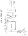
- Fig. 12 is a block diagram showing structure of a prior art ultrasonic Doppler blood flow velocity detecting apparatus.
- numeral 1 is an ultrasonic-wave probe generally comprising a piezoelectric device for transmitting ultrasonic waves into a human body 2 and for receiving an echo signal from the human body 2, which is used for obtaining blood-flow information of the blood flowing in vessel 3 at velocity V.
- Numeral 4 is a driving circuit for producing transmission signal Tx for generating ultrasonic wave by the ultrasonic-wave probe 1.
- Numeral 5 is a Doppler signal detecting circuit for quadrature-detecting the echo signal Rx received by the ultrasonic-wave probe 1 to output quadrature Doppler signals Vdx and Vdy.
- Numerals 6 and 7 are A/D converters respectively for A/D converting the quadrature Doppler signals Vdx and Vdy into quadrature Doppler signals Ddx and Ddy of the form of numerical value.
- Numeral 12 is frequency analyzer for frequency analyzing the quadrature Doppler signals Ddx and Ddy through a calculating method, for example, fast Fourier transformation method (FFT).
- Numeral 13 is a display for indicating frequency of Doppler signals in the form of sonogram.
- Numeral 15 is a control circuit for controlling the drive circuit 4, Doppler signal detection circuit 5, and A/D converters 6 and 7.
- the drive circuit 4 generates transmission signal Tx in response to a control signal from the control circuit 15, which transmits ultrasonic waves into the human body 2 through the ultrasonic-wave probe 1.
- the ultrasonic waves propagating through the human body 2 is reflected at the blood and reaches the piezoelectric device of the ultrasonic probe 1 with delay time proportional to depth of the portion where ultrasonic waves are reflected. If the reflective object moves, the echo signal is subjected to Doppler effect with Doppler shift frequency fd in accordance with the relation of the above-mentioned Eq. (1).
- Frequency of the echo signal received by the ultrasonic-wave probe 31 is fc+fd by Doppler effect.
- the echo signal is quadrature-detected with a quadrature reference signals R of frequency fc by the Doppler signal detecting circuit 5 to output Doppler signals Vdx and Vdy.
- These Doppler signals Vdx and Vdy have quadrature relation each other and are of frequency fd which is obtained from difference between frequency fc + fd of the echo signal Ec and frequency fc of the quadrature reference signal.
- the A/D converters 6 and 7 sample in response to a sampling clock Sp sent from the control circuit 40 and A/D-converts the Doppler signals Vdx and Vdy to send digital values Ddx and Ddy to the frequency analyzer 12.
- the frequency analyzer 38 performs frequency analyzing plural values of equally spaced points of the Doppler signals Ddx and Ddy through FFT method, etc. and indicates the result on display 13, such as television display to provide diagnosis data.
- resolution of low frequency components is increased by lowering sampling frequency of Doppler signal.
- lowering the sampling frequency decreases Nyquist frequency fnq so that overlap occurs if Doppler frequency fd exceeds Nyquist frequency fnq. Therefore, when components of low velocity out of various velocity component of a blood flow is tried to be observed, observation of low velocity components is disturbed due to overlap caused by high velocity components.
- the present invention has been developed in order to remove the above-described drawbacks inherent to the conventional ultrasonic Doppler blood flow velocity detection apparatus.
- an ultrasonic Doppler blood flow velocity detection apparatus comprising: signal producing means for producing trigger pulses, sampling clock pulses having a given phase relation with said trigger pulses, and a pair of quadrature signals of a given frequency; transducing means for transmitting ultrasonic waves in response to said trigger pulses and for receiving ultrasonic waves reflected at an ultrasonic-wave reflective object and converting the received ultrasonic waves into an electric echo signal; Doppler shift detection means responsive to said pair of quadrature signals and said echo signal for detecting Doppler shift and outputting Doppler signals; sampling means for sampling said Doppler signals in response to said sampling pulses averaging means responsive to said sampling clock pulses and an output of said sampling means for averaging plural consecutive samples of said Doppler shift, thereby producing a signal indicative of flow velocity of said ultrasonic-wave reflective object.
- a second apparatus further comprises a weighting circuit responsive to the output of the Doppler detection circuit, and the sampling clock for weighting every value of the plural time-different values in accordance with predetermined weighting coefficients.
- Fig. 1 is a block diagram of an ultrasonic Doppler blood flow meter.
- numeral 1 is an ultrasonic-wave probe generally comprising an unshown piezoelectric transducer for transmitting ultrasonic waves into a human body 2 and for receiving an echo signal from the human body 2, which is used for obtaining information of blood flowing in a vessel 3 at velocity V.
- Numeral 4 is a driving circuit for producing transmission signal Tx.
- the transmission signal Tx is sent to an ultrasonic-wave probe 1 which generates ultrasonic waves in response to the transmission signal Tx.
- the ultrasonic waves transmitted from the probe 1 are reflected by the blood in the human body 2.
- the probe 1 receives reflected ultrasonic waves as echo signal.
- Numeral 5 is a Doppler signal detecting circuit for performing quadrature-detection of the echo signal Ec received by the ultrasonic-wave probe 1 to output quadrature Doppler signals Vdx and Vdy.
- Numerals 6 and 7 are A/D converters respectively for A/D-converting quadrature Doppler signals Vdx and Vdy into quadrature Doppler signals Ddx and Ddy of numerical forms.
- Numerals 8 and 9 are adding circuits for accumulating plural sets of sampled values of Doppler signals Ddx and Ddy to determine a mean value or average value, the number of the sets being predetermined.
- Numerals 10 and 11 are latches for holding added results from adding circuits 8 and 9.
- Numeral 12 is a frequency analyzer for frequency-analyzing the averaged Doppler signals Mdx and Mdy.
- Numeral 13 is a display for indicating the result of frequency analyzing in the form of sonograph.
- Numeral 14 is a frequency divider for dividing a first sampling clock SP1 generated by a signal generator 15 to produce a second sampling clocks SP2.
- the signal generator 15 produces repetition trigger pulses, quadrature reference signals rx and ry, and a first sampling clock SP1.
- the trigger pulses are sent to the drive circuit 4 to produce the transmission signal Tx.
- the quadrature reference signals rx and ry are sent to the Doppler signal detection circuit 5.
- the first sampling clock SP1 is sent to A/D converters 6 and 7, adding circuits 8 and 9, and divider 14.
- the drive circuit 4 generates the transmission signal Tx in response to the repetition trigger pulses from the signal generator 15.
- the transmission signal Tx is sent to the ultrasonic-wave probe 1 which transmits ultrasonic waves into the human body 2 by the unshown piezoelectric transducer of the ultrasonic-wave probe 1.
- the ultrasonic waves are reflected at the blood in the blood vessel of the human body 2.
- the reflected ultrasonic waves returns to the piezoelectric transducer of the ultrasonic probe 1, as an echo signal. If the echo signal received by piezoelectric device is subjected to Doppler effect, its frequency becomes fc+fd.
- the echo signal is converted into electric echo signal Ec which is sent to the Doppler signal detection apparatus.
- the echo signal Ec is quadrature-detected with a quadrature reference signals rx and ry of frequency fc by the Doppler signal detection circuit 5 which outputs Doppler signals Vdx and Vdy. These Doppler signals Vdx and Vdy have quadrature relationship each other. Therefore, the Doppler signal detection circuit 5 produces a difference frequency signal of frequency fd between the echo signal Ec, i.e., of frequency fc+fd and the quadrature reference signal of frequency fc.
- the A/D converters 6 and 7 sample Doppler signals Vdx and Vdy in response to the first sampling clock SP1 sent from the signal generator 15 and converts the Doppler signals Vdx and Vdy into digital values.
- the frequency divider 14 divides the first sampling clock SP1 to send the second sampling clock SP2 to reset inputs R of adding circuit 8 and 9 and latch clock inputs of the latches 10 and 11.
- the adding circuits 8 and 9 add A-input value to B-input value to output an added value at M output in response to the first sampling clock SP1 incoming to C input. These added values are latched by the latches 10 and 11 in response to the second sampling clock SP2.
- the latched signals are sent to the frequency analyzer 12.
- the frequency analyzer 12 performs frequency analyzing the Doppler signals Mdx and Mdy through FFT (fast Fourier transformation). The analyzed result is displayed on the display 13.
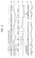
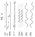
- waveform 20 shows the sampling clock SP1; waveform 21, Doppler signal Ddx or Ddy outputted from the A/D converters 6 and 7; waveform 22, the sampling clock SP2; waveform 23, Doppler signal mean values Mdx or Mdy outputted from the latches 10 and 11; waveform 24, a clock obtained from the second sampling clock SP2 by time-contraction; waveform 25, Doppler signal mean values Mdy or Mdy where waveforms 24 and 25 are indicated with time base contracted for convenience.
- Doppler signals Ddx(n) and Ddy(n) obtained at n th pulse of the first sampling clock SP1 are applied to A-inputs of the adding circuits 8 and 9 and added to the value of B-input value respectively.
- the result of each adding circuit is outputted from M output in response to (n+1) th pulse of the first sampling clock SP1 applied to C-input.
- the initial value of B-input is zero.
- subsequent Doppler signals Ddx(n+1) and Ddy(n+1) are outputted from the A/D converters 6 and 7 in response to (n+1) th pulse of the first sampling clock SP1 and applied to A-input of the adding circuits 8 and 9 respectively.
- next (n+1) th data are added to the result of n th data.
- A-input and B-input values of the adding circuits 8 and 9 are added to output at M-output and to be applied to B-input.
- P th pulse M-output is latched and the adding circuits 8 and 9 are reset. Therefore, all Doppler signals of n th to (n+3) th pulse of the first sampling clock SP2 are added and the result is outputted at M-output and held at p th pulse of the divided second sampling clock SP2 by the latches 10 and 11.
- lowering sampling frequency increases frequency of limit where overlap begins to occur.
- the first limit lies in the second sampling clock SP2 of frequency f2, given by: fd ⁇ f2/2 Therefore, Doppler signal higher than this frequency cannot be indicated. Under this condition, no overlap occurs.
- the second limit of frequency f1 of the first sampling clock SP2 is given by: fd ⁇ f1/2 Therefore, Doppler signal frequency higher than this frequency produces overlap and thus disturbs the observation. Accordingly, sufficiently higher frequency of the frequency f1 of the first sampling clock SP1 increases advantageous effect of the invention.
- the first sampling clock SP1 In the ultrasonic Doppler blood flow velocity detection apparatus using continuous waves, because Doppler signal is obtained continuously, it is possible to set the first sampling clock SP1 extremely high.
- the second sampling clock SP2 is selected in accordance with flow velocity.
- frequency of the first sampling clock SP1 is equal to repetition frequency of transmitting and receiving of ultrasonic-wave pulses, which is determined by distance to the portion to be measured and propagation velocity of ultrasonic waves.
- the frequency of the second sampling clock SP2 is determined in accordance with blood flow velocity.
- the Doppler signal detected by the Doppler detection circuit 5 is sampled at A/D converters 6 and 7; a mean value is determined from data of n th to (n+m) th sampling by the averaging circuit comprising a divider 14, adding circuits 8 and 9, latches 10 and 11 as P th mean value, as shown in the waveforms 21-23; and the frequency analyzer 12 performs frequency analyzing using from P th to P+ l th mean values determined similarly.
- averaging adjacent plural data can suppress noise components and thus provide high SN ratio.
- low-velocity blood flow can be observed clearly with high SN ratio because overlap does not adversely affect low-velocity blood flow measuring, for it is possible to attenuate a Doppler signal whose cycle is shorter than that of two sets of data respectively sampled at n th and (n+m) th pulses. More specifically, noise components are cancelled each other when these components are accumulated by the adding circuits 8 and 9 because noise components occur at random and are sinusoidal components. On the other hand, low-velocity components of Doppler signal whose frequency is lower than f1 but higher f2, does not decrease when accumulating.
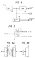
- Fig. 4 is a block diagram of the signal generator 15.
- a pulse generator 51 generates trigger pulses applied to the drive circuit 4, a timer 52, and reference signal generator. As shown in Fig. 3, the trigger pulse is generated at every interval T.
- the timer 52 generates the first sampling clocks SP1 in response to trigger pulse with time delay Td.
- the reference signal generator 53 generates quadrature reference signals rx and ry in response to the trigger pulse, the quadrature reference signals having phase difference of 90° each other, as shown in waveforms 29.
- Fig. 5 is a block diagrams of the Doppler signal detection circuit 5. In Fig.
- Fig.6 is a block diagram of the adding circuits 8 and 9.
- a full adder 8a adds A-input value to B-input value.
- A-input is responsive to an output of A/D converter 6 or 7.
- B-input responses to Q-output of a data latch 8b which is reset by the second sampling clock SP2 to zero at first.
- the data latch 8b stores D-input value from the adder 8a in response to the sampling clock SP1 through terminal C.
- the adder 8a adds the firstly added data to new coming data from the A/D converter 6 or 7. This operation is repeated until next sampling clock SP2 arrives at the CL input of the latch 8b, so that values of Doppler signal are accumulated in the latch 8b until the second sampling clock SP2 reaches CL-input.
- the latch 8b is reset.
- the mean value M is obtained from Q-output of the latch 8b, the number of averaging original sampling data of Doppler signal Vdx or Vdy being determined by frequency relationship between the sampling clocks SP1 and SP2, i.e., dividing ratio of the divider 14.
- Fig. 7 is a block diagram of an adding circuit 8′ which produces weighted mean values M′.
- an adder 8a adds A-input value to B-input value.
- A-input is responsive to an output of A/D converter 6 or 7.
- a multiplier 8c sends a signal whose value is the same as the value applied therein, the signal being sent to the adder 8a.
- the adder 8a adds Doppler signal to an output of the latch 8b in the same way as first embodiment.
- the data latch 8b stores D-input value from the adder 8a in response to the sampling clock SP1 through terminal C and is reset by the second Sampling pulse SP2 applied to CL-input thereof. Therefore, the added data is once held in the data latch 8b. The held data is applied to the B-input of the adder 8a, so that values of Doppler signal are accumulated in the latch 8b until the second sampling clock SP2 reaches CL-input.
- a counter 8d counts up the first sampling clocks SP1 and is reset by the second sampling clock SP2. The count indicates which data incoming to the adder 8b with respect to the second sampling clock SP2.
- an output of the counter 8d is used as an address signal of the ROM table 8e which stores coefficients and outputs respective coefficients in accordance with count of the counter 8d.
- the ROM table 8e stores coefficients 0.5, 1.0, 1.0, and 0.5.
- the coefficient from the ROM table is applied to the multiplier 8c.
- coefficients 0.5, 1.0, 1.0, and 0.5 are successively outputted in response to the sampling clock SP1 or address signal from the counter 8d.
- the multiplier 8d multiplies Doppler signal by the coefficient which varies with count of the address signal from the counter 8d.
- an weight mean value M′ is obtained from Q-output of the latch 8b, the number of coefficients is the same as that of averaging original sampling data of Doppler signal Vdx or Vdy.
- the divider can be replace with the counter 8d. More over CL-input of the counter 8d can be omitted if initial condition of the counter 8d is consistent with that of divider 14 and the full count of the counter is consistent with the dividing ratio of the divider 14.
- Weighting as shown in Fig. 7 has an effect equivalently obtained by a digital pass filter.
- a Doppler signal whose shift frequency exceeds ⁇ 1/2 ⁇ f2(frequency of sampling clock SP2) cannot be analyzed by the frequency analyzer 12 or displayed on the display 13.
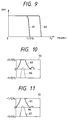
- weighting enables analyzing and displaying such Doppler signal which causes overlapping, as shown in Figs 9-11.
- curve 61 shows a frequency characteristic of weighting circuit when all weighting coefficients are 1.0.
- a Doppler signal is indicated up to a half of second sampling clock frequency f2.
- weighting coefficients are 0.5, 1.0 ,1.0, and 0.5, the frequency characteristic is expanded as shown by curve 62.
- Frequncy components of the Doppler signal exceeds 1/2 ⁇ f2 are indicated or not indiceted on the display 13, as shown Figs. 10 and 11. Such components are indicated on the display 13, as shown by curve 67 of a solid line.
- the curve 67 is indicated a range between 0 to -1/2 ⁇ f2. However, actual range is over 1/2 ⁇ f2.
- curve 64 of a dot line When all coefficients are 1.0, such components are not indicated on the display 13, as shown by curve 64 of a dot line. Therefore, various display ranges necessary for diagnosis can be selected from several sets of coefficient tables.
Landscapes
- Engineering & Computer Science (AREA)
- Physics & Mathematics (AREA)
- Radar, Positioning & Navigation (AREA)
- Remote Sensing (AREA)
- Health & Medical Sciences (AREA)
- Life Sciences & Earth Sciences (AREA)
- Acoustics & Sound (AREA)
- Computer Networks & Wireless Communication (AREA)
- General Physics & Mathematics (AREA)
- Pathology (AREA)
- Medical Informatics (AREA)
- Nuclear Medicine, Radiotherapy & Molecular Imaging (AREA)
- Hematology (AREA)
- Radiology & Medical Imaging (AREA)
- Biomedical Technology (AREA)
- Heart & Thoracic Surgery (AREA)
- Biophysics (AREA)
- Molecular Biology (AREA)
- Surgery (AREA)
- Animal Behavior & Ethology (AREA)
- General Health & Medical Sciences (AREA)
- Public Health (AREA)
- Veterinary Medicine (AREA)
- Ultra Sonic Daignosis Equipment (AREA)
Claims (5)
- Appareil à ultrasons pour détecter la vitesse d'écoulement du sang par effet Doppler, comprenant :
un moyen (15) de production de signaux pour produire des impulsions de déclenchement, des impulsions d'horloge d'échantillonnage présentant une relation de phase donnée avec lesdites impulsions de déclenchement, et une paire de signaux en quadrature d'une fréquence donnée;
un moyen transducteur (1) pour émettre des ondes ultrasonores en réponse auxdites impulsions de déclenchement et pour recevoir les ondes ultrasonores réfléchies par un objet réfléchissant les ondes ultrasonores et transformer les ondes ultrasonores reçues en signaux d'écho électriques;
un moyen (5) de détection de décalage Doppler réagissant à ladite paire de signaux en quadrature et audit signal d'écho pour détecter le décalage Doppler et les signaux Doppler sortants (Vdx, Vdy);
des moyens d'échantillonnage (6, 7) pour échantillonner lesdits signaux Doppler en réponse auxdites impulsions d'échantillonnage,
des moyens (8, 9, 14) de calcul de moyenne réagissant auxdites impulsions d'horloge d'échantillonnage et à un signal de sortie dudit moyen d'échantillonnage pour effectuer la moyenne d'une pluralité d'échantillons consécutifs du décalage Doppler, de manière à produire ainsi un signal indicatif de la vitesse d'écoulement dudit objet réfléchissant les ondes ultrasonores. - Appareil à ultrasons pour détecter la vitesse d'écoulement du sang par effet Doppler selon la revendication 1, dans lequel lesdits moyens de calcul de moyenne comprennent :(a) un moyen (14) de division de fréquence réagissant à ladite impulsion d'horloge d'échantillonnage pour une division de fréquence de ladite impulsion d'horloge d'échantillonnage;(b) des moyens de verrouillage (10, 11) réagissant à ladite impulsion d'horloge d'échantillonnage et audit signal de sortie dudit moyen de division pour en maintenir la valeur d'entrée; et(c) des moyens d'addition (8, 9) sensibles audit décalage Doppler et destinés à additionner ledit décalage Doppler à un signal de sortie desdits moyens de verrouillage de manière que la valeur totale de ladite pluralité de valeurs dont le nombre est déterminé par la relation entre lesdites impulsions et ledit signal de sortie du moyen de division soit déterminée.
- Appareil à ultrasons pour détecter la vitesse d'écoulement du sang par effet Doppler selon la revendication 2, comprenant, en outre, des moyens (10, 11) de décalage de bits réagissant audit signal de sortie desdits moyens de verrouillage pour obtenir la valeur moyenne de ladite pluralité de valeurs à partir de ladite valeur totale.
- Appareil à ultrasons pour détecter la vitesse d'écoulement du sang selon les revendications 1, 2 ou 3, comprenant, en outre :(e) un moyen de pondération (84) réagissant audit signal de sortie dudit moyen de détection Doppler et à ladite impulsion d'horloge d'échantillonnage pour peser chaque valeur de ladite pluralité de valeurs différentes dans le temps en fonction de coefficients de pondération prédéterminés.
- Appareil à ultrasons pour détecter la vitesse d'écoulement du sang par effet Doppler selon la revendication 4, dans lequel ledit moyen de pondération comprend :(a) un moyen de comptage (8d) réagissant auxdites impulsions d'horloge d'échantillonnage pour compter lesdites impulsions d'horloge d'échantillonnage;(b) un moyen de stockage (8e) réagissant à un signal de sortie dudit moyen de comptage pour générer lesdits coefficients de pondération; et(c) un moyen de multiplication (8c) réagissant audit décalage Doppler et à un signal de sortie dudit moyen de stockage pour multiplier ledit signal Doppler par ledit coefficient.
Applications Claiming Priority (2)
| Application Number | Priority Date | Filing Date | Title |
|---|---|---|---|
| JP322655/88 | 1988-12-21 | ||
| JP63322655A JPH07106202B2 (ja) | 1988-12-21 | 1988-12-21 | 超音波ドップラ血流計 |
Publications (2)
| Publication Number | Publication Date |
|---|---|
| EP0375441A1 EP0375441A1 (fr) | 1990-06-27 |
| EP0375441B1 true EP0375441B1 (fr) | 1995-05-10 |
Family
ID=18146120
Family Applications (1)
| Application Number | Title | Priority Date | Filing Date |
|---|---|---|---|
| EP89313468A Expired - Lifetime EP0375441B1 (fr) | 1988-12-21 | 1989-12-21 | Appareil pour la détection des vitesses d'écoulement du sang par effet Doppler à ultrasons |
Country Status (4)
| Country | Link |
|---|---|
| US (1) | US5065764A (fr) |
| EP (1) | EP0375441B1 (fr) |
| JP (1) | JPH07106202B2 (fr) |
| DE (1) | DE68922595T2 (fr) |
Families Citing this family (13)
| Publication number | Priority date | Publication date | Assignee | Title |
|---|---|---|---|---|
| US5198989A (en) * | 1980-09-23 | 1993-03-30 | Ads Environmental Services, Inc. | Sewer flow measurement control system |
| JPH04336056A (ja) * | 1991-05-10 | 1992-11-24 | Matsushita Electric Ind Co Ltd | 超音波ドプラ映像装置 |
| US5287753A (en) * | 1992-05-02 | 1994-02-22 | Advanced Technology Laboratories, Inc. | Continuous display of peak and mean blood flow velocities |
| US5463905A (en) * | 1993-02-23 | 1995-11-07 | Baird; James D. | Portable non-invasive flowmeter for partially filled pipe |
| US5550537A (en) * | 1994-05-06 | 1996-08-27 | Endress + Hauser, Inc. | Apparatus and method for measuring mass flow rate of a moving medium |
| US5634465A (en) * | 1995-06-09 | 1997-06-03 | Advanced Technology Laboratories, Inc. | Continuous display of cardiac blood flow information |
| JP3177677B2 (ja) * | 1996-05-14 | 2001-06-18 | 松下電器産業株式会社 | 超音波連続波ドプラ血流計 |
| US5868676A (en) * | 1996-10-25 | 1999-02-09 | Acuson Corporation | Interactive doppler processor and method |
| US5844144A (en) * | 1997-03-04 | 1998-12-01 | Jennings; Gordon H. | Method for estimating flow velocity |
| US5808195A (en) * | 1997-05-21 | 1998-09-15 | Ads Environmental Services | Arrangement for determining liquid velocity versus depth utilizing historical data |
| CN110596713A (zh) * | 2019-09-19 | 2019-12-20 | 电子科技大学 | 一种声学多普勒测流系统 |
| KR102704750B1 (ko) * | 2021-02-09 | 2024-09-11 | 한국전자통신연구원 | 복수 단계의 다운 샘플링을 수행하는 유속 센서 및 이의 동작 방법 |
| CN114796867B (zh) * | 2022-05-25 | 2024-12-31 | 深圳市本尚医疗科技有限公司 | 一种预防下肢深静脉血栓的系统及其使用方法 |
Family Cites Families (9)
| Publication number | Priority date | Publication date | Assignee | Title |
|---|---|---|---|---|
| US3798590A (en) * | 1968-09-12 | 1974-03-19 | Us Navy | Signal processing apparatus including doppler dispersion correction means |
| CA1135827A (fr) * | 1978-12-04 | 1982-11-16 | Rainer Fehr | Methode de mesure de vitesses de debit en mesurant la difference de phase entre signaux doppler |
| US4265126A (en) * | 1979-06-15 | 1981-05-05 | General Electric Company | Measurement of true blood velocity by an ultrasound system |
| US4612937A (en) * | 1983-11-10 | 1986-09-23 | Siemens Medical Laboratories, Inc. | Ultrasound diagnostic apparatus |
| JPH0693890B2 (ja) * | 1985-04-30 | 1994-11-24 | 株式会社東芝 | 超音波診断装置 |
| JP2544342B2 (ja) * | 1986-01-22 | 1996-10-16 | 株式会社日立製作所 | 超音波ドップラ―診断装置 |
| JPS6395037A (ja) * | 1986-10-09 | 1988-04-26 | アロカ株式会社 | 超音波パルスドプラ装置 |
| US4790323A (en) * | 1986-11-03 | 1988-12-13 | Hewlett-Packard Company | Flow imaging detector |
| FR2617982B1 (fr) * | 1987-07-09 | 1989-10-27 | Labo Electronique Physique | Dispositif d'elimination d'echos fixes pour echographe ultrasonore |
-
1988
- 1988-12-21 JP JP63322655A patent/JPH07106202B2/ja not_active Expired - Fee Related
-
1989
- 1989-12-19 US US07/452,653 patent/US5065764A/en not_active Expired - Lifetime
- 1989-12-21 EP EP89313468A patent/EP0375441B1/fr not_active Expired - Lifetime
- 1989-12-21 DE DE68922595T patent/DE68922595T2/de not_active Expired - Fee Related
Also Published As
| Publication number | Publication date |
|---|---|
| US5065764A (en) | 1991-11-19 |
| EP0375441A1 (fr) | 1990-06-27 |
| DE68922595T2 (de) | 1995-09-28 |
| JPH07106202B2 (ja) | 1995-11-15 |
| DE68922595D1 (de) | 1995-06-14 |
| JPH02167146A (ja) | 1990-06-27 |
Similar Documents
| Publication | Publication Date | Title |
|---|---|---|
| US4803990A (en) | Examining moving objects by ultrasound echograpy | |
| US5662115A (en) | Method for determining the velocity-time spectrum of blood flow | |
| Brandestini | Topoflow-A digital full range Doppler velocity meter | |
| US5065764A (en) | Ultrasonic doppler blood flow velocity detection apparatus | |
| US4790323A (en) | Flow imaging detector | |
| US20020019590A1 (en) | Ultrasound diagnostic apparatus and method for measuring blood flow velocity using doppler effect | |
| US20020016547A1 (en) | Ultrasound diagnostic apparatus and method for measuring blood flow velocity using doppler effect | |
| KR100459616B1 (ko) | 도플러 효과를 이용하여 인체 조직 속도를 측정하기 위한초음파 진단 장치 및 방법 | |
| US5818735A (en) | Method and system for high resolution time-of-flight measurements | |
| EP0228070A2 (fr) | Dispositif diagnostique ultrasonique à effet Doppler | |
| US4799490A (en) | Doppler ultrasonic diagnostic apparatus | |
| US4809249A (en) | Apparatus for ultrasound flow mapping | |
| JP2640657B2 (ja) | 超音波ドプラ計 | |
| EP0807825B1 (fr) | Débitmètre ultrasonique sanguin à effet Doppler et émission continue | |
| US4713971A (en) | Device for determining the velocity in a flowing fluid by use of the acoustic Doppler-effect | |
| US5062430A (en) | Device for measuring the speed of blood flows by ultrasonic echography at an increased measuring speed | |
| JP3281435B2 (ja) | 超音波ドプラ診断装置 | |
| JPS6096232A (ja) | 超音波血流測定装置 | |
| JP2563656B2 (ja) | 超音波ドプラ映像装置 | |
| EP0474867B1 (fr) | Procede de traitement d'un signal doppler | |
| JP3642834B2 (ja) | 超音波ドプラ診断装置 | |
| JP2594994B2 (ja) | パルスドプラ計測装置 | |
| US5216639A (en) | Method for processing a doppler signal | |
| EP0430094A1 (fr) | Méthode et appareil d'imagerie du débit sanguin dans un corps vivant | |
| JP3391578B2 (ja) | 相関装置および流れ情報表示装置 |
Legal Events
| Date | Code | Title | Description |
|---|---|---|---|
| PUAI | Public reference made under article 153(3) epc to a published international application that has entered the european phase |
Free format text: ORIGINAL CODE: 0009012 |
|
| 17P | Request for examination filed |
Effective date: 19900108 |
|
| AK | Designated contracting states |
Kind code of ref document: A1 Designated state(s): DE FR GB |
|
| 17Q | First examination report despatched |
Effective date: 19920730 |
|
| GRAA | (expected) grant |
Free format text: ORIGINAL CODE: 0009210 |
|
| AK | Designated contracting states |
Kind code of ref document: B1 Designated state(s): DE FR GB |
|
| ET | Fr: translation filed | ||
| REF | Corresponds to: |
Ref document number: 68922595 Country of ref document: DE Date of ref document: 19950614 |
|
| PLBE | No opposition filed within time limit |
Free format text: ORIGINAL CODE: 0009261 |
|
| STAA | Information on the status of an ep patent application or granted ep patent |
Free format text: STATUS: NO OPPOSITION FILED WITHIN TIME LIMIT |
|
| 26N | No opposition filed | ||
| REG | Reference to a national code |
Ref country code: GB Ref legal event code: IF02 |
|
| PGFP | Annual fee paid to national office [announced via postgrant information from national office to epo] |
Ref country code: FR Payment date: 20051208 Year of fee payment: 17 |
|
| PGFP | Annual fee paid to national office [announced via postgrant information from national office to epo] |
Ref country code: DE Payment date: 20051215 Year of fee payment: 17 |
|
| PGFP | Annual fee paid to national office [announced via postgrant information from national office to epo] |
Ref country code: GB Payment date: 20051221 Year of fee payment: 17 |
|
| PG25 | Lapsed in a contracting state [announced via postgrant information from national office to epo] |
Ref country code: DE Free format text: LAPSE BECAUSE OF NON-PAYMENT OF DUE FEES Effective date: 20070703 |
|
| GBPC | Gb: european patent ceased through non-payment of renewal fee |
Effective date: 20061221 |
|
| REG | Reference to a national code |
Ref country code: FR Ref legal event code: ST Effective date: 20070831 |
|
| PG25 | Lapsed in a contracting state [announced via postgrant information from national office to epo] |
Ref country code: GB Free format text: LAPSE BECAUSE OF NON-PAYMENT OF DUE FEES Effective date: 20061221 |
|
| PG25 | Lapsed in a contracting state [announced via postgrant information from national office to epo] |
Ref country code: FR Free format text: LAPSE BECAUSE OF NON-PAYMENT OF DUE FEES Effective date: 20070102 |