EP0375855A1 - Mandrin à mâchoires actionné mécaniquement pour serrage des pièces, en particulier des vilebrequins - Google Patents
Mandrin à mâchoires actionné mécaniquement pour serrage des pièces, en particulier des vilebrequins Download PDFInfo
- Publication number
- EP0375855A1 EP0375855A1 EP89118843A EP89118843A EP0375855A1 EP 0375855 A1 EP0375855 A1 EP 0375855A1 EP 89118843 A EP89118843 A EP 89118843A EP 89118843 A EP89118843 A EP 89118843A EP 0375855 A1 EP0375855 A1 EP 0375855A1
- Authority
- EP
- European Patent Office
- Prior art keywords
- axis
- clamping
- clamping head
- chuck
- rotation
- Prior art date
- Legal status (The legal status is an assumption and is not a legal conclusion. Google has not performed a legal analysis and makes no representation as to the accuracy of the status listed.)
- Withdrawn
Links
- 125000006850 spacer group Chemical group 0.000 description 2
- 230000001154 acute effect Effects 0.000 description 1
- 238000006073 displacement reaction Methods 0.000 description 1
- 230000000694 effects Effects 0.000 description 1
- 238000000034 method Methods 0.000 description 1
Images


Classifications
-
- B—PERFORMING OPERATIONS; TRANSPORTING
- B23—MACHINE TOOLS; METAL-WORKING NOT OTHERWISE PROVIDED FOR
- B23B—TURNING; BORING
- B23B31/00—Chucks; Expansion mandrels; Adaptations thereof for remote control
- B23B31/02—Chucks
- B23B31/10—Chucks characterised by the retaining or gripping devices or their immediate operating means
- B23B31/12—Chucks with simultaneously-acting jaws, whether or not also individually adjustable
- B23B31/16—Chucks with simultaneously-acting jaws, whether or not also individually adjustable moving radially
- B23B31/16233—Jaws movement actuated by oblique surfaces of a coaxial control rod
-
- B—PERFORMING OPERATIONS; TRANSPORTING
- B23—MACHINE TOOLS; METAL-WORKING NOT OTHERWISE PROVIDED FOR
- B23B—TURNING; BORING
- B23B31/00—Chucks; Expansion mandrels; Adaptations thereof for remote control
- B23B31/02—Chucks
- B23B31/36—Chucks with means for adjusting the chuck with respect to the working-spindle
Definitions
- the invention relates to a power-operated jaw chuck for workpieces to be eccentrically clamped, in particular crankshafts, the clamping axis running parallel and eccentrically to the axis of rotation of the chuck, with a chuck base which can be fastened coaxially to the axis of rotation on a lathe spindle, a chuck which is held on the chuck base and the setting of the eccentricity of the clamping axis
- the clamping head in which radially centrally adjustable force-actuated clamping jaws are guided and on which, in the region of the axis of rotation, a workpiece holder aligning the workpiece before its clamping with a pair of at least one movable force-actuated directional jaw is provided, the workpiece holder being radial opens towards the chuck edge in the direction through the clamping axis for inserting the workpiece and the movable straightening jaw is also guided on the clamping head.
- Chucks of this type are described in DE 34 46 687 A1.
- the chuck base is, in principle, a chuck flange that enables connection to the lathe spindle, on which the clamping head is slidably guided and can be locked in its guidance by being clamped against the chuck base by means of an adjusting spindle via a spacer that determines its position.
- the clamping jaws and wedge rods actuating them are guided in the clamping head and are axially positively, but displaceably suspended in the adjustment direction of the clamping head on a clamping plate connecting them with a driving piston and fixed on the driving piston.
- a separate axially movable wedge rod is also used to actuate the movable straightening jaw, which, like the wedge rods for the clamping jaws, is slidably suspended on a second clamping plate, which is firmly connected to a second driving piston provided for driving only the straightening jaw, which is coaxial with the clamping piston for the clamping jaws and is guided to the axis of rotation of the feed base in the latter.
- the clamping head apart from the clamping plates and the driving pistons, forms a complete jaw chuck that is adjustable according to the crank stroke of the workpiece on the chuck base.
- unbalance balancing weights are slidably guided on the clamping head in the same adjustment direction as the clamping head. They are adjusted on the clamping head in the opposite direction to its own displacement and, in their respective position, are clamped against the clamping head by means of a spindle using suitable spacers.
- the invention has for its object to design a jaw chuck of the type mentioned so that the masses of the clamping head and the balancing weights and thus the residual unbalance, but also the mass of the jaw chuck as a whole, are as small as possible.
- the force actuators for the clamping jaws and the movable straightening jaw are arranged in the clamping head, which is rotatably mounted on the chuck base about an axis of rotation parallel to the axis of rotation and to the axis of rotation, which is at a radial distance from the axis of rotation , which is equal to half the length dimension by which the eccentricity of the clamping axis should be maximally adjustable with respect to the axis of rotation, that furthermore the clamping head can be adjusted by an angle adjustable size by a power drive acting between the chuck base and clamping head and can be locked in its respective rotational positions on the chuck base , and that the chuck base with the clamping head about the axis of rotation and the clamping head are balanced around the turning axis.
- the axis of rotation and the turning axis have a position fixed to the body with respect to the chuck base and the turning axis and the clamping axis.
- the distance between the axis of rotation and the axis of clamping changes, by a maximum of twice the distance between the turning axis and the axis of rotation.
- the distance between the axis of rotation and the clamping axis determines the eccentricity, which can thus be adjusted by turning the clamping head relative to the chuck base.
- the orientation of the workpiece holder and the straightening jaws also change in relation to the loading direction specified by the workpiece loading devices for inserting the workpieces into the workpiece holder.
- the chuck In order to be able to continue inserting the workpieces, after turning the clamping head relative to the chuck base, the chuck must be turned back by the same angle or by the additional angle to 360 ° so that the direction of the workpiece holder in which the workpieces are inserted into the workpiece holder can again correspond to the loading direction of the workpiece loading devices provided for this purpose.
- This adjustment of the standstill position of the chuck can be easily mastered in modern lathes with a C axis controlled with respect to the angle of rotation of the lathe spindle. As a result, the idle position of the lathe spindle becomes counter to or co-rotating with the rotation of the clamping head about the same or that Additional angle changed to 360 °.
- a particularly preferred embodiment of the invention is characterized in that the clamping head can be rotated through an angle of 180 ° between two end positions in which the clamping axis, the turning axis and the axis of rotation lie in a common plane.
- the workpiece is aligned with respect to the plane corresponding in both end positions of the clamping head rotation through the three axes mentioned.
- the straightening jaws coordinated with this level as the straightening level therefore do not require any changes in order to be adapted to both end positions. Only the effective depth of the workpiece holder is to be adapted to the changed workpiece dimensions, which is easily possible by changing suitable depth stops or the like.
- the straightening jaws must, however, be adapted to the plane through the axis of rotation and the clamping axis as a straightening plane, which, however, is not rigid with respect to the clamping head, so that the straightening jaws in each case require different top jaws that are adapted to the course of the straightening plane.
- the clamping head has a pin coaxial with the turning axis, which is mounted in a bore in the chuck base and has circumferential teeth that mesh with oppositely moving toothed racks on the pin, which are driven by the power drive for the clamping head rotation forming cylinder piston units arranged in the chuck base.
- This arrangement has the advantage that the opposing movement of the toothed racks and the pistons driving them does not produce any imbalances.
- an arrangement is preferably recommended in which an imbalance balancing weight is guided radially in a recess in the chuck base, which is adjustable with the rotation of the clamping head and with a control projection in a circumferential direction on the clamping head extending tax groove.
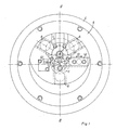
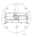
- the jaw chuck is used for eccentric clamping of crankshafts, the axially seen outline of which is indicated by dashed lines in FIGS. 1 and 2.
- the jaw chuck consists in its basic structure of a chuck which can be fastened coaxially on a lathe spindle with an axis of rotation 3, not shown, and a clamping head, generally designated 5, with clamping jaws 6, which are radial to one with the
- the axis of rotation 3 is guided parallel to the clamping axis 7 and is connected via axially movable wedge rods 8 via a clamping plate 10 to an annular driving piston 9 which is axially adjustable in the clamping head 5.
- the clamping head 5 is equipped in the region of the axis of rotation 3 with a workpiece holder 11 aligning the workpiece 1 before its clamping and with a pair of straightening jaws 12, 12 ', of which in the exemplary embodiment the straightening jaw 12 is movable and can be adjusted in a force-actuated manner.
- the workpiece holder 11 opens radially towards the chuck edge in the direction through the clamping axis 7 for inserting the workpiece.
- the movable straightening jaw 12 is also guided radially in the direction of arrow 13 to a turning axis 14, which is still to be described in detail, on the clamping head 5 and, like the clamping jaws 6, can be adjusted via a wedge bar by a power drive arranged in the clamping head 5, as shown in the drawing known, is not shown.
- the clamping head 5 is rotatably mounted on the chuck base 4 about the turning axis 14 already mentioned, which is parallel to the rotation axis 3 and the clamping axis 7.
- This turning axis 14 has a radial distance a from the axis of rotation 3, which is equal to half the length dimension b (FIG. 4), by which the eccentricity of the clamping axis 7 with respect to the axis of rotation 3 should be maximally adjustable.
- the clamping head 5 can be adjusted by an angle adjustable size by a force drive acting between chuck base 1 and clamping head 5, generally designated 15, and can be locked in its respective rotational positions on the chuck base 1 by a locking device, generally designated 16.
- the feed base 1 with the clamping head 5 is balanced about the axis of rotation 3 and the clamping head 5 for itself about the turning axis 14.
- the clamping head 5 can be rotated through an angle of 180 ° between two end positions A, B, in which the clamping axis 7, the turning axis 14 and the axis of rotation 5 lie in a common plane.
- 4 shows the mutual position of these axes 5, 7, 14 in the end positions A and B in a body-fixed reference system related to the clamping head 5. If the distance between the clamping axis 7 and the turning axis 14, there is a change in the distance h between the clamping axis 7 and the axis of rotation 3 and thus the change in eccentricity between the two end positions, A, B to twice the distance a between the axis of rotation 3 and the turning axis 14. In principle, intermediate layers C, D, ... be realized.
- the axis of rotation 3, the turning axis 14 and the clamping axis 7 then no longer lie in a common plane. Rather, the plane 18 through the clamping axis 7 and the turning axis 14 on the one hand and the plane 17 through the clamping axis 7 and the axis of rotation 3 on the other enclose an angle G, the maximum size of which tang G a / given is.
- the straightening jaws 12 must be matched to the plane 17 by the clamping axis 7 and the axis of rotation 3. However, this level is not rigid, so that for each setting C, D, ... the straightening jaws 12 must be adapted to the different positions of the level 17 as a straightening level by means of suitable top jaws. Only in the end positions A and B does the leveling plane 17 for the straightening jaws 12 coincide with the plane 18 common to all three axes, so that the straightening jaws 12 12, when only the end positions A and B are set, do not require any changes.
- a centering tip 21, which is force-actuated by a piston 20 in the clamping head 5, is provided concentrically with the clamping axis 7.
- the clamping head 5 is supported on the chuck base 1 via bearings 21.
- the clamping head 5 has a pin 22 coaxial with the turning axis 14, which is mounted in a bore 23 of the chuck base 1.
- the pin 22 has a circumferential toothing 24 which mesh with toothed racks 25 located opposite one another on the pin 22 and moving in opposite directions.
- the toothed racks 25 can be acted upon on both sides by cylinder piston units 26 which are arranged in the chuck base 1 and which form the power drive for the clamping head rotation.
- An axial extension of the pin 22 is designed as a pressure medium distribution system 23, via which channels of the chuck base acted upon by the pressure medium in a known manner, with corresponding channels in the pin 22 in Are connected, which supply the various cylinder spaces in the clamping head 5 with pressure medium.
- an imbalance compensation weight 30 is guided radially in a recess 29 in the chuck base 1.
- This unbalance balance weight 30 is automatically adjustable with the rotation of the clamping head 5.
- the unbalance compensation weight 30 is provided in the exemplary embodiment with a control projection 31 which engages in a control groove 32 which extends in the circumferential direction on the clamping head 5 and which essentially represents a spiral groove around the turning axis 14, so that when the clamping head 5 is rotated the unbalance compensation weight 30 is applied Control groove 32 is adjusted radially in the desired manner.
- Hirth-toothed lower rings 16.1, 16.2 on the clamping head 5 and on the chuck base 1 and an upper ring 16.3 engaging on the lower rings with corresponding counter teeth serve to lock the clamping head 5.
- the upper ring 16.3 is axially adjustable against the lower rings 16.1, 16.2 with a cylinder piston unit 33.
- the locking state is monitored by a control linkage consisting of the rods 34 and 35 and a two-armed lever 36 connecting them.
- a control of the rotational position of the clamping head 5 is possible in that a rod 37 guided centrally in the lathe spindle is articulated via a sleeve 38 with the pin 22 is connected and the sleeve 38 or the rod 37 is assigned a sensor, not shown, which detects the rotational position at a suitable position.
Landscapes
- Engineering & Computer Science (AREA)
- Mechanical Engineering (AREA)
- Gripping On Spindles (AREA)
Applications Claiming Priority (2)
| Application Number | Priority Date | Filing Date | Title |
|---|---|---|---|
| DE3844343 | 1988-12-30 | ||
| DE19883844343 DE3844343C2 (de) | 1988-12-30 | 1988-12-30 | Kraftbetätigtes Backenspannfutter für exzentrisch zu spannende Werkstücke, insbesondere Kurbelwellen |
Publications (1)
| Publication Number | Publication Date |
|---|---|
| EP0375855A1 true EP0375855A1 (fr) | 1990-07-04 |
Family
ID=6370543
Family Applications (1)
| Application Number | Title | Priority Date | Filing Date |
|---|---|---|---|
| EP89118843A Withdrawn EP0375855A1 (fr) | 1988-12-30 | 1989-10-11 | Mandrin à mâchoires actionné mécaniquement pour serrage des pièces, en particulier des vilebrequins |
Country Status (3)
| Country | Link |
|---|---|
| EP (1) | EP0375855A1 (fr) |
| JP (1) | JPH02212004A (fr) |
| DE (1) | DE3844343C2 (fr) |
Cited By (5)
| Publication number | Priority date | Publication date | Assignee | Title |
|---|---|---|---|---|
| CN101804469A (zh) * | 2010-04-28 | 2010-08-18 | 南车戚墅堰机车有限公司 | 车偏心孔夹具 |
| JP2013208690A (ja) * | 2012-03-30 | 2013-10-10 | Komatsu Ntc Ltd | チャック装置及び切削装置 |
| CN109352509A (zh) * | 2018-11-27 | 2019-02-19 | 无锡机床股份有限公司 | 超精机的偏心轴调节机构 |
| CN114985546A (zh) * | 2022-04-29 | 2022-09-02 | 沈阳飞机工业(集团)有限公司 | 带自锁导管端头校形装置及其方法 |
| CN118875950A (zh) * | 2024-09-30 | 2024-11-01 | 南通聚灿电动工具有限公司 | 一种铝合金轮毂的抛光设备 |
Families Citing this family (2)
| Publication number | Priority date | Publication date | Assignee | Title |
|---|---|---|---|---|
| JP2004174676A (ja) * | 2002-11-28 | 2004-06-24 | Toyo Advanced Technologies Co Ltd | 工作物の加工方法および工作機械の主軸 |
| EP3344411B1 (fr) * | 2015-09-02 | 2023-06-07 | Wielandts UPMT | Mandrin pour une machine-outil de haute précision |
Citations (3)
| Publication number | Priority date | Publication date | Assignee | Title |
|---|---|---|---|---|
| GB1040192A (en) * | 1965-01-07 | 1966-08-24 | Fischer Walter | Improvements in and relating to a chuck |
| DE3446687A1 (de) * | 1984-12-21 | 1986-07-03 | Günter Horst 7927 Sontheim Röhm | Kraftbetaetigtes backenspannfutter fuer exzentrisch zu spannende werkstuecke |
| EP0250724A2 (fr) * | 1986-07-04 | 1988-01-07 | Günter Horst Röhm | Mandrin de serrage concentrique pour machines à tourner |
-
1988
- 1988-12-30 DE DE19883844343 patent/DE3844343C2/de not_active Expired - Fee Related
-
1989
- 1989-10-11 EP EP89118843A patent/EP0375855A1/fr not_active Withdrawn
- 1989-12-20 JP JP33245089A patent/JPH02212004A/ja active Pending
Patent Citations (3)
| Publication number | Priority date | Publication date | Assignee | Title |
|---|---|---|---|---|
| GB1040192A (en) * | 1965-01-07 | 1966-08-24 | Fischer Walter | Improvements in and relating to a chuck |
| DE3446687A1 (de) * | 1984-12-21 | 1986-07-03 | Günter Horst 7927 Sontheim Röhm | Kraftbetaetigtes backenspannfutter fuer exzentrisch zu spannende werkstuecke |
| EP0250724A2 (fr) * | 1986-07-04 | 1988-01-07 | Günter Horst Röhm | Mandrin de serrage concentrique pour machines à tourner |
Cited By (6)
| Publication number | Priority date | Publication date | Assignee | Title |
|---|---|---|---|---|
| CN101804469A (zh) * | 2010-04-28 | 2010-08-18 | 南车戚墅堰机车有限公司 | 车偏心孔夹具 |
| JP2013208690A (ja) * | 2012-03-30 | 2013-10-10 | Komatsu Ntc Ltd | チャック装置及び切削装置 |
| CN109352509A (zh) * | 2018-11-27 | 2019-02-19 | 无锡机床股份有限公司 | 超精机的偏心轴调节机构 |
| CN109352509B (zh) * | 2018-11-27 | 2023-05-12 | 无锡机床股份有限公司 | 超精机的偏心轴调节机构 |
| CN114985546A (zh) * | 2022-04-29 | 2022-09-02 | 沈阳飞机工业(集团)有限公司 | 带自锁导管端头校形装置及其方法 |
| CN118875950A (zh) * | 2024-09-30 | 2024-11-01 | 南通聚灿电动工具有限公司 | 一种铝合金轮毂的抛光设备 |
Also Published As
| Publication number | Publication date |
|---|---|
| DE3844343C2 (de) | 1998-06-04 |
| JPH02212004A (ja) | 1990-08-23 |
| DE3844343A1 (de) | 1990-07-05 |
Similar Documents
| Publication | Publication Date | Title |
|---|---|---|
| DE3510259C2 (fr) | ||
| EP3760352A1 (fr) | Mandrin á compensation pour le serrage de pièces dans centres d'usinage | |
| DE2102412C3 (de) | Verstellvorrichtung an Kurbelwellenschleifmaschinen zum Ausrichten der zu schleifenden Kurbelzapfen | |
| EP0185883B1 (fr) | Mandrin à mors actionné mécaniquement | |
| DE3238442C2 (de) | Fräsvorrichtung zum Erzeugen von Polygonprofilen | |
| EP0013908A1 (fr) | Mandrin à mâchoires pivotantes pour machines à tourner | |
| DE3701446C2 (de) | Innenrundschleifmaschine | |
| DE3844343C2 (de) | Kraftbetätigtes Backenspannfutter für exzentrisch zu spannende Werkstücke, insbesondere Kurbelwellen | |
| EP1238730B1 (fr) | Mandrin de serrage | |
| EP0250724B1 (fr) | Mandrin de serrage concentrique pour machines à tourner | |
| EP0355256B1 (fr) | Mandrin de serrage excentrique de pièces | |
| EP1428612A1 (fr) | Dispositif et procédé de positionnement angulaire de pièces excentriques telles que des villebrequins, par l'intermédiaire de mâchoires montées sur une lunette de centrage | |
| DE2128618A1 (de) | Schwenkfutter zur bearbeitung von werkstuecken unter mehreren sich kreuzenden achsen | |
| DE2346111C3 (de) | An einer Schleifmaschine angeordnete Aufspann- und Teileinrichtung für Kugelnaben oder dergleichen zum Schleifen ihrer Zylinderringnuten | |
| DE3446826C2 (fr) | ||
| DE2627573A1 (de) | Spannfutterbetaetigungsmechanismus | |
| DE2648997A1 (de) | Spannwerkzeug mit einzelverstellung und zusaetzlicher zentralspannung | |
| DE2611923A1 (de) | Backenfutter | |
| DE2158427C3 (de) | Schwenkfutter für Werkzeugmaschinen | |
| DE1552745A1 (de) | Verzahnungsmaschine mit einer Teileinrichtung zum Ausrichten der Werkstueckzaehne fuer gleiche Spanabnahme an den gegenueberliegenden Zahnflanken | |
| DE186709C (fr) | ||
| DE4102975C2 (fr) | ||
| AT344471B (de) | Vorrichtung zum entfernen des aeusseren ringwulstes von im elektrischen widerstands-stumpfschweissverfahren hergestellten rohrstoessen | |
| DE667328C (de) | Einspannvorrichtung fuer Drehbaenke zur Bearbeitung von Achsen, Wellen o. dgl. | |
| DE2855964A1 (de) | Drehbank-schwenkfutter |
Legal Events
| Date | Code | Title | Description |
|---|---|---|---|
| PUAI | Public reference made under article 153(3) epc to a published international application that has entered the european phase |
Free format text: ORIGINAL CODE: 0009012 |
|
| 17P | Request for examination filed |
Effective date: 19900307 |
|
| AK | Designated contracting states |
Kind code of ref document: A1 Designated state(s): DE ES FR GB IT SE |
|
| 17Q | First examination report despatched |
Effective date: 19910524 |
|
| STAA | Information on the status of an ep patent application or granted ep patent |
Free format text: STATUS: THE APPLICATION HAS BEEN WITHDRAWN |
|
| 18W | Application withdrawn |
Withdrawal date: 19911121 |
|
| R18W | Application withdrawn (corrected) |
Effective date: 19911121 |