EP0375893A2 - Montage pour modifier la précision de fréquence d'un oscillateur de référence utilisé dans la radio-technique - Google Patents
Montage pour modifier la précision de fréquence d'un oscillateur de référence utilisé dans la radio-technique Download PDFInfo
- Publication number
- EP0375893A2 EP0375893A2 EP89120642A EP89120642A EP0375893A2 EP 0375893 A2 EP0375893 A2 EP 0375893A2 EP 89120642 A EP89120642 A EP 89120642A EP 89120642 A EP89120642 A EP 89120642A EP 0375893 A2 EP0375893 A2 EP 0375893A2
- Authority
- EP
- European Patent Office
- Prior art keywords
- frequency
- reference oscillator
- circuit arrangement
- converter
- data
- Prior art date
- Legal status (The legal status is an assumption and is not a legal conclusion. Google has not performed a legal analysis and makes no representation as to the accuracy of the status listed.)
- Withdrawn
Links
Images
Classifications
-
- H—ELECTRICITY
- H03—ELECTRONIC CIRCUITRY
- H03L—AUTOMATIC CONTROL, STARTING, SYNCHRONISATION OR STABILISATION OF GENERATORS OF ELECTRONIC OSCILLATIONS OR PULSES
- H03L7/00—Automatic control of frequency or phase; Synchronisation
- H03L7/06—Automatic control of frequency or phase; Synchronisation using a reference signal applied to a frequency- or phase-locked loop
- H03L7/16—Indirect frequency synthesis, i.e. generating a desired one of a number of predetermined frequencies using a frequency- or phase-locked loop
- H03L7/18—Indirect frequency synthesis, i.e. generating a desired one of a number of predetermined frequencies using a frequency- or phase-locked loop using a frequency divider or counter in the loop
-
- H—ELECTRICITY
- H03—ELECTRONIC CIRCUITRY
- H03L—AUTOMATIC CONTROL, STARTING, SYNCHRONISATION OR STABILISATION OF GENERATORS OF ELECTRONIC OSCILLATIONS OR PULSES
- H03L7/00—Automatic control of frequency or phase; Synchronisation
- H03L7/06—Automatic control of frequency or phase; Synchronisation using a reference signal applied to a frequency- or phase-locked loop
- H03L7/08—Details of the phase-locked loop
- H03L7/085—Details of the phase-locked loop concerning mainly the frequency- or phase-detection arrangement including the filtering or amplification of its output signal
- H03L7/093—Details of the phase-locked loop concerning mainly the frequency- or phase-detection arrangement including the filtering or amplification of its output signal using special filtering or amplification characteristics in the loop
Definitions
- the invention relates to a circuit arrangement for improving the frequency accuracy and reducing the circuit complexity of a reference oscillator used in radio technology, in particular for mobile telephones according to the preamble of the main claim.
- the base station prescribes a specific data rate which is demodulated at 5.28 kHz.
- the data frequency of 5.28 kHz accurate to ⁇ 10 ⁇ 8 for regulating the frequency of the free-swinging quartz-stabilized reference oscillator.
- the frequency of a free-running oscillator (6.758 MHz) is divided down in a microprocessor and with the data frequency compared.
- the output of the microprocessor, which affects the result of this comparison, and the frequency of the free-running oscillator is given to a difference former, so that an exact frequency of 6.584 MHz is present at its output.
- the reference oscillator is part of a PLL circuit which has a frequency divider connected to the oscillator, a phase comparison stage and a low-pass filter which is connected between the oscillator and the phase comparison stage.
- the phase comparison stage thus receives on the one hand a voltage with the frequency of 12.8 MHz of the oscillator divided by 1250 and on the other hand a voltage with the frequency of 67584 MHz divided by 66, ie a frequency of 102.4 kHz is settled.
- the output voltage of the phase comparison stage is fed to the reference oscillator as a control voltage or regulating voltage via the low-pass filter.
- Such a reference frequency control according to the prior art has a relatively complex control loop, the number of components being relatively large and, owing to the increased number of components, the power consumption is also relatively high.
- the present invention is therefore based on the object of providing a circuit arrangement for improving the frequency accuracy of a reference oscillator according to the preamble, which has a reduced number of components compared to the prior art and has a lower power consumption, with high frequency accuracy being to be ensured.
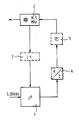
- the single figure shows a circuit configuration of the circuit arrangement according to the invention.
- the base station sends a data clock, which is demodulated in the mobile station at 5.2 kHz, this frequency having an accuracy of 10 ⁇ 8.
- the frequency of the data clock is used in a control loop as a comparison frequency for regulating the reference frequency of the reference oscillator of the mobile station.
- the received data clock is fed to a microprocessor 1, which is connected to a free-running, temperature-compensated, quartz-stabilized oscillator 2.
- the frequency of the reference oscillator is selected such that it is an integral multiple of the data frequency and is preferably 16.5 MHz in the exemplary embodiment.
- a prescaler 3 can be provided between the reference oscillator 2 and the microprocessor 1, but is only necessary for certain, slow types of microprocessor.
- the microprocessor divides the frequency of the reference oscillator 2 by 3125 (without prescaler) and compares this divided frequency with the frequency of the data clock.
- the voltage representing the result of this comparison is applied to a D / A converter 4 which is connected to the output of the microprocessor 1 and which is connected to the control input of the reference oscillator 2.
- the digital signal supplied by the microprocessor which represents a deviation from the reference frequency of the reference oscillator, is converted into an analog signal and supplied to the reference oscillator 2 as a control voltage or control voltage.
- a low-pass filter 5 can be connected between D / A converter 4 and reference oscillator 2, which suppresses interference.
- the D / A converter 4 can be designed as an 8-bit converter The accuracy can still be improved if, for example, a 12-bit converter, ie a converter with a higher number of bits is used.
- a microprocessor 1 is used as a divider and comparator.
- counters and comparison stages can be provided that perform the same function.
- a lower or a higher frequency can also be used as the frequency for the reference oscillator 2 if it is divisible by 5280.
- the microprocessor 1 and the digital / analog converter 4 can also be used for further functions in the mobile station, in which case a further control loop is formed, for example a common mode compensation can be carried out.
- switches for example a multiplexer, and a sample and hold circuit are connected between the D / A converter 4 and the reference oscillator, the sample and hold circuit being connected to the control input of the reference oscillator and having a further output for the common-mode control.
Landscapes
- Stabilization Of Oscillater, Synchronisation, Frequency Synthesizers (AREA)
- Superheterodyne Receivers (AREA)
- Transceivers (AREA)
Applications Claiming Priority (2)
| Application Number | Priority Date | Filing Date | Title |
|---|---|---|---|
| DE3843835 | 1988-12-24 | ||
| DE19883843835 DE3843835A1 (de) | 1988-12-24 | 1988-12-24 | Schaltungsanordnung zur verbesserung der frequenzgenauigkeit eines in der funktechnik verwendeten referenzoszillators |
Publications (2)
| Publication Number | Publication Date |
|---|---|
| EP0375893A2 true EP0375893A2 (fr) | 1990-07-04 |
| EP0375893A3 EP0375893A3 (fr) | 1990-09-05 |
Family
ID=6370222
Family Applications (1)
| Application Number | Title | Priority Date | Filing Date |
|---|---|---|---|
| EP19890120642 Withdrawn EP0375893A3 (fr) | 1988-12-24 | 1989-11-08 | Montage pour modifier la précision de fréquence d'un oscillateur de référence utilisé dans la radio-technique |
Country Status (2)
| Country | Link |
|---|---|
| EP (1) | EP0375893A3 (fr) |
| DE (1) | DE3843835A1 (fr) |
Families Citing this family (1)
| Publication number | Priority date | Publication date | Assignee | Title |
|---|---|---|---|---|
| DE19733079A1 (de) * | 1997-07-31 | 1999-02-04 | Techno Trend Systemtechnik Gmb | Verfahren zur Erzeugung einer Referenzfrequenz bei Frequenzumsetzern |
Family Cites Families (8)
| Publication number | Priority date | Publication date | Assignee | Title |
|---|---|---|---|---|
| US3913028A (en) * | 1974-04-22 | 1975-10-14 | Rca Corp | Phase locked loop including an arithmetic unit |
| US4316152A (en) * | 1979-09-24 | 1982-02-16 | Hewlett-Packard Company | Data tracking phase locked loop |
| US4322842A (en) * | 1979-10-23 | 1982-03-30 | Altran Electronics | Broadcast system for distribution automation and remote metering |
| US4528521A (en) * | 1984-02-09 | 1985-07-09 | At&T Information Systems Inc. | Precision control frequency synthesizer having an unstable, variable frequency input signal |
| DE3540178A1 (de) * | 1985-11-13 | 1987-05-21 | Telefonbau & Normalzeit Gmbh | Schaltungsanordnung zur phasenregelung |
| DE3604965C1 (de) * | 1986-02-17 | 1987-09-10 | Nixdorf Computer Ag | Verfahren und Schaltungsanordnung zum Synchronisieren eines insbesondere einer Vermittlungseinrichtung zugehoerigen spannungsgesteuerten Oszillators |
| DE3677606D1 (de) * | 1986-11-22 | 1991-03-28 | Ant Nachrichtentech | Verfahren zur synchronisation auf im zeitmultiplexbetrieb ausgesendete signale und zur taktgewinnung hieraus. |
| US4752748A (en) * | 1987-04-16 | 1988-06-21 | Amdahl Corporation | Intelligent phase-locked loop |
-
1988
- 1988-12-24 DE DE19883843835 patent/DE3843835A1/de not_active Ceased
-
1989
- 1989-11-08 EP EP19890120642 patent/EP0375893A3/fr not_active Withdrawn
Also Published As
| Publication number | Publication date |
|---|---|
| EP0375893A3 (fr) | 1990-09-05 |
| DE3843835A1 (de) | 1990-07-05 |
Similar Documents
| Publication | Publication Date | Title |
|---|---|---|
| DE68918857T2 (de) | Digitaler Empfänger mit Unter-Nyquistabtastrate. | |
| DE69635573T2 (de) | Frequenzsynthetisierer | |
| EP0406469B1 (fr) | Circuit de commande numérique pour des systèmes d'accord | |
| DE2455052C2 (de) | Signalübertragungsanlage | |
| DE3841512A1 (de) | Takthalteschaltung | |
| DE3147578C2 (fr) | ||
| EP1063766A2 (fr) | Modulateur pour moduler en phase et en fréquence utilisant une boucle à verrouillage de phase , et procédé | |
| DE2333851A1 (de) | Verfahren und anordnungen zur selbsttaetigen nachregelung der mit einer abstimmanordnunggeingestellten oszillatorfrequenz eines ueberlagerungsempfangsteils einer bild und/oder tonwiedergabeanordnung | |
| EP0119439A2 (fr) | Mélangeur à diode avec commande de tension de polarisation et son application | |
| EP0375893A2 (fr) | Montage pour modifier la précision de fréquence d'un oscillateur de référence utilisé dans la radio-technique | |
| EP1109319A2 (fr) | Dispositif de génération et transposition de signal d'horloge | |
| DE3943072C2 (fr) | ||
| EP0025876A1 (fr) | Radiotéléphone à plusieurs canaux | |
| EP0046835B1 (fr) | Appareil de radiotélécommunication à canaux multiples pour les modes de fonctionnement "intercommunication" et/ou "téléphonie bidirectionnelle alternative" | |
| EP0374374B1 (fr) | Procédé et dispositif pour réduire par un codage la largeur de bande utile d'un signal à largeur de bande limitée et procédé et dispositif pour décoder le signal à largeur de bande limitée | |
| DE3738124C2 (de) | Eine die Trägerwelle des FM-Synthesators für ein Telefonsystem steuernde Schaltung | |
| DE3707839A1 (de) | Elektronische abstimmeinrichtung | |
| DE3626792C2 (fr) | ||
| DE69310964T2 (de) | Verfahren und Vorrichtung zur automatischen Schleifensteuerung | |
| DE3411883A1 (de) | Einstellbarer, phasenverriegelter frequenzgenerator | |
| DE3146956A1 (de) | Automatische abstimmfrequenzsteuerung fuer einen empfaenger | |
| DE60021315T2 (de) | Funksender | |
| DE3025228C2 (de) | Generator mit digitaler Frequenzeinstellung | |
| DE2941712C2 (fr) | ||
| EP0182982A1 (fr) | Circuit oscillateur |
Legal Events
| Date | Code | Title | Description |
|---|---|---|---|
| PUAI | Public reference made under article 153(3) epc to a published international application that has entered the european phase |
Free format text: ORIGINAL CODE: 0009012 |
|
| AK | Designated contracting states |
Kind code of ref document: A2 Designated state(s): AT CH DE FR GB IT LI NL SE |
|
| PUAL | Search report despatched |
Free format text: ORIGINAL CODE: 0009013 |
|
| AK | Designated contracting states |
Kind code of ref document: A3 Designated state(s): AT CH DE FR GB IT LI NL SE |
|
| STAA | Information on the status of an ep patent application or granted ep patent |
Free format text: STATUS: THE APPLICATION IS DEEMED TO BE WITHDRAWN |
|
| 18D | Application deemed to be withdrawn |
Effective date: 19910306 |