EP0375926A2 - Entstörumhüllung, insbesondere für eine Zündverteilerkappe - Google Patents
Entstörumhüllung, insbesondere für eine Zündverteilerkappe Download PDFInfo
- Publication number
- EP0375926A2 EP0375926A2 EP19890121481 EP89121481A EP0375926A2 EP 0375926 A2 EP0375926 A2 EP 0375926A2 EP 19890121481 EP19890121481 EP 19890121481 EP 89121481 A EP89121481 A EP 89121481A EP 0375926 A2 EP0375926 A2 EP 0375926A2
- Authority
- EP
- European Patent Office
- Prior art keywords
- interference suppression
- cap
- ignition distributor
- interference
- distributor cap
- Prior art date
- Legal status (The legal status is an assumption and is not a legal conclusion. Google has not performed a legal analysis and makes no representation as to the accuracy of the status listed.)
- Granted
Links
Images
Classifications
-
- F—MECHANICAL ENGINEERING; LIGHTING; HEATING; WEAPONS; BLASTING
- F02—COMBUSTION ENGINES; HOT-GAS OR COMBUSTION-PRODUCT ENGINE PLANTS
- F02P—IGNITION, OTHER THAN COMPRESSION IGNITION, FOR INTERNAL-COMBUSTION ENGINES; TESTING OF IGNITION TIMING IN COMPRESSION-IGNITION ENGINES
- F02P7/00—Arrangements of distributors, circuit-makers or -breakers, e.g. of distributor and circuit-breaker combinations or pick-up devices
- F02P7/02—Arrangements of distributors, circuit-makers or -breakers, e.g. of distributor and circuit-breaker combinations or pick-up devices of distributors
- F02P7/021—Mechanical distributors
- F02P7/025—Mechanical distributors with noise suppression means specially adapted for the distributor
-
- H—ELECTRICITY
- H04—ELECTRIC COMMUNICATION TECHNIQUE
- H04B—TRANSMISSION
- H04B15/00—Suppression or limitation of noise or interference
- H04B15/02—Reducing interference from electric apparatus by means located at or near the interfering apparatus
Definitions
- the invention is based on an interference suppression envelope according to the preamble of claim 1.
- an interference suppression envelope known from DE-AS 23 14 460
- recesses are provided through which spring hooks engage, which come to rest on a detent recess of an ignition distributor cap and thus open the ignition distributor cap hold the distributor housing.
- This recess also serves to secure the interference suppression casing on the ignition distributor cap.
- the possibility is advantageously given to connect a ground cable to the interference suppression sheath as desired.
- a ground cable can be retrofitted at any time.
- the measures listed in the subclaims provide advantageous developments of the solution specified in claim 1.
- one element of the plug connection is embedded with its fastening end into the interference-suppression casing made of plastic. This is an advantageous manufacturing method. It is advantageous to use the flat plug connection customary in motor vehicle construction according to claim 3 and according to claim 4 to attach the element close to a possibility of grounding, so that the ground cable to be installed can be kept very short.
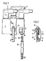
- FIG. 1 shows the view of an ignition distributor cap with interference suppression casing and FIG. 2 shows a partial section through the ignition distributor cap according to line II-II of FIG. 1.
- FIG. 1 a side view of an interference suppression sleeve made of conductive plastic in the form of an interference suppression cap 1 is placed on an ignition distributor cap 2 hidden underneath.
- the interference cap protruding connection dome 3 of the ignition distributor cap, on which dome cable connector 4 are placed.
- a spring hook 6 for fastening the ignition distributor cap can be seen in FIG. 1, which is shown in section in FIG. 2.
- This spring hook is enclosed at its one curved end 7 by a retaining clip 8 which is screwed to the ignition distributor housing 9 which carries the ignition distributor cap.
- This housing is made of metal, is electrically conductive and thus represents a ground connection.
- the other end 11 of the spring hook is bent in an S-shaped manner in a known manner and is suitable for snapping into a detent depression 12, which is provided at the foot 13 of the distributor cap 2.
- the interference-suppression cap made of electrically conductive plastic has a recess 15, so that the spring hook can reach through to the locking trough 12 without mechanically loading the interference-suppression cap.
- this can be secured by means of hooks 19 which engage behind the end face of the ignition distributor cap at its foot end.
- a sheet-shaped end 17 of a plug-in lug 18 is embedded in the wall of the interference-suppression cap 1 near the recess-side edge thereof, that is, it is encased with conductive plastic.
- This embedding can also be carried out by subsequent injection into a previously provided recess in the wall of the interference suppression cap.
- the plug-in lug is part of a plug-in connection, which can be attached to a correspondingly different part of a plug-in connection, here a flat plug 20 which is common in motor vehicle construction.
- This tab is located at the end of a ground strap 21, which is made in the usual way from copper wire mesh and on its other end has a second tab 22, which can be plugged onto a correspondingly connected grounding lug, which is not shown here.
Landscapes
- Engineering & Computer Science (AREA)
- Chemical & Material Sciences (AREA)
- Combustion & Propulsion (AREA)
- Mechanical Engineering (AREA)
- General Engineering & Computer Science (AREA)
- Computer Networks & Wireless Communication (AREA)
- Signal Processing (AREA)
- Connector Housings Or Holding Contact Members (AREA)
- Details Of Connecting Devices For Male And Female Coupling (AREA)
- Shielding Devices Or Components To Electric Or Magnetic Fields (AREA)
- Noise Elimination (AREA)
- Ignition Installations For Internal Combustion Engines (AREA)
Abstract
Description
- Die Erfindung geht aus von einer Entstörumhüllung gemäß der Gattung des Patentanspruchs 1. Bei einer solchen durch die DE-AS 23 14 460 bekannten Entstörumhüllung sind Ausnehmungen vorgesehen, durch die Federhaken greifen, die zur Auflage an einer Rastmulde einer Zündverteilerkappe kommen und somit die Zündverteilerkappe auf dem Zündverteilergehäuse halten. Diese Ausnehmung dient zugleich als Sicherung der Entstörumhüllung an der Zündverteilerkappe. Dabei ist es jedoch nicht gewährleistet, daß ein sicherer elektrisch leitender Kontakt zwischen Entstörumhüllung und Federhaken hergestellt ist, der selbst metallisch ausgeführt und elektrisch leitend eine Verbindung zur Masse darstellt. Es sind Ausführungen bekannt, bei denen in aufwendiger Weise zwischen der Auflage des Federhakens an der Zündverteilerkappe und dem Federhaken geformte Metallbleche eingelegt werden, die ihrerseits zur Herstellung eines elektrisch leitenden Kontakts zum Federhaken zwischen Zündverteilerkappe und Entstörumhüllung federnd eingespannt sind. Eine solche Kontaktierung der Entstörumhüllung mit einer Masseverbindung ist jedoch sehr aufwendig sowohl in der Herstellung als auch in der Montage. Zudem besteht die Gefahr, daß Gebrauch bei Wartungsarbeiten die Metalleinlegebleche verlorengehen und durch neue ersetzt werden müssen. Es sind auch Entstörumhüllungen bekannt, bei denen für die Masseverbindung das Ende eines Massekabels unlösbar, z. B. durch Löten mit der metallisch ausgeführten Entstörumhüllung verbunden ist. Andererseits ist es jedoch nicht immer notwendig, daß die Endstörumhüllung auch tatsächlich mit Hilfe eines Massebandes geerdet werden muß. Diese Erdung ist insbesondere bei der Nahentstörung der Zündanlage notwendig. In den überwiegenden Fällen von Neufahrzeugen kann deshalb auf ein Masseband verzichtet werden und dementsprechend Kosten eingespart werden.
- Mit der erfindungsgemäßen Entstorumhüllung mit den kennzeichnenden Merkmalen des Patentanspruchs 1 erhält man in vorteilhafter Weise die Möglichkeit ein Massekabel je nach Belieben mit der Entstörumhüllung zu verbinden. Insbesondere kann ein solches Massekabel jederzeit nachgerüstet werden. Durch die in den Unteransprüchen aufgeführten Maßnahmen sind vorteilhafte Weiterbildungen der im Anspruch 1 angegebenen Lösung wiedergegeben. In besonders vorteilhafter Weise wird das eine Element der Steckverbindung mit seinem Befestigungsende in die aus Kunststoff bestehende Entstörumhüllung eingebettet. Dies stellt ein vorteilhaftes Herstellungsverfahren dar. Dabei ist es vorteilhaft, sich der im Kfz-Bau üblichen Flachsteckerverbindung zu bedienen gemäß Anspruch 3 und gemäß Anspruch 4 das Element nahe einer Möglichkeit zur Erdung anzubringen, so daß das einzubauende Massekabel sehr kurz gehalten werden kann.
- Ein Ausführungsbeispiel ist in der Zeichnung dargestellt und wird in der nachfolgenden Beschreibung näher beschrieben. Es zeigt Figur 1 die Ansicht einer Zündverteilerkappe mit Entstörumhüllung und Figur 2 einen Teilschnitt durch die Zündverteilerkappe gemäß Linie II-II von Figur 1.
- In der Figur 1 ist in Seitenansicht eine aus leitfähigem Kunststoff bestehende Entstörumhüllung in Form einer Entstörkappe 1 auf eine darunter verborgene Zündverteilerkappe 2 aufgesetzt. Die Entstörkappe überragenden Anschlußdome 3 der Zündverteilerkappe, auf welche Dome Kabelstecker 4 aufgesetzt sind. Zur Befestigung der Zündverteilerkappe ist ein Federhaken 6 in Figur 1 erkennbar, der in Figur 2 im Schnitt dargestellt ist. Dieser Federhaken ist an seinem einen gekrümmten Ende 7 von einer Halteschelle 8 umschlossen, die mit dem die Zündverteilerkappe tragenden Zündverteilergehäuse 9 verschraubt ist. Dieses Gehäuse ist aus Metall, elektrisch leitend und stellt somit eine Masseverbindung dar. Das andere Ende 11 des Federhakens ist in bekannter Weise S-förmig gebogen und geeignet in eine Rastmulde 12, die am Fuße 13 der Zündverteilerkappe 2 vorgesehen ist, einzuschnappen. Im Bereich dieser Rastmulde weist die aus elektrisch leitfähigem Kunststoff bestehende Entstörkappe eine Ausnehmung 15 auf, so daß der Federhaken ohne die Entstörkappe mechanisch zu belasten zur Rastmulde 12 hindurchgreifen kann. Zur axialen Sicherung der Störkappe an der Zündverteilerkappe kann diese mittels Haken 19, die die Stirnseite der Zündverteilerkappe an ihrem fußseitigen Ende hintergreifen, gesichert werden.
- Wie nun Figur 1 entnehmbar, ist in die Wand der Entstörkappe 1 nahe dem ausnehmungsseitigen Rand derselben ein blattförmiges Ende 17 einer Steckfahne 18 eingebettet, d. h. mit leitfähigem Kunststoff umhüllt. Diese Einbettung kann auch durch nachträgliches Einspritzen in eine zuvor vorgesehene Ausnehmung in der Wand der Entstörkappe vorgenommen werden. Die Steckfahne ist Teil einer Steckverbindung, welches ein entsprechend anderes Teil einer Steckverbindung, hier ein im Kraftfahrzeugbau üblicher Flachstecker 20 aufsteckbar ist. Dieser Flachstecker befindet sich am Ende eines Massebandes 21, das in üblicher Weise aus Kupferdrahtgeflecht hergestellt ist und das an seinem anderen Ende einen zweiten Flachstecker 22 aufweist, der auf eine entsprechend mit Masse verbundene Steckfahne, die hier nicht weiter gezeigt ist, aufsteckbar ist.
- Die hier am Beispiel einer aus leitendem Kunststoff bestehenden Entstörkappe beschriebenen Ausgestaltung läßt sich auch an metallisch ausgeführten Entstörumhüllungen verwirklichen.
Claims (4)
Applications Claiming Priority (2)
| Application Number | Priority Date | Filing Date | Title |
|---|---|---|---|
| DE3843760A DE3843760A1 (de) | 1988-12-24 | 1988-12-24 | Entstoerumhuellung, insbesondere fuer eine zuendverteilerkappe |
| DE3843760 | 1988-12-24 |
Publications (3)
| Publication Number | Publication Date |
|---|---|
| EP0375926A2 true EP0375926A2 (de) | 1990-07-04 |
| EP0375926A3 EP0375926A3 (de) | 1991-06-05 |
| EP0375926B1 EP0375926B1 (de) | 1994-09-21 |
Family
ID=6370162
Family Applications (1)
| Application Number | Title | Priority Date | Filing Date |
|---|---|---|---|
| EP89121481A Expired - Lifetime EP0375926B1 (de) | 1988-12-24 | 1989-11-21 | Entstörumhüllung, insbesondere für eine Zündverteilerkappe |
Country Status (4)
| Country | Link |
|---|---|
| EP (1) | EP0375926B1 (de) |
| JP (1) | JPH02222232A (de) |
| DE (2) | DE3843760A1 (de) |
| ES (1) | ES2061895T3 (de) |
Cited By (1)
| Publication number | Priority date | Publication date | Assignee | Title |
|---|---|---|---|---|
| FR2700224A1 (fr) * | 1993-01-07 | 1994-07-08 | Sagem Allumage | Procédé d'antiparasitage et tête antiparasitée de distributeur de véhicule automobile. |
Families Citing this family (1)
| Publication number | Priority date | Publication date | Assignee | Title |
|---|---|---|---|---|
| DE19509793C2 (de) * | 1995-03-17 | 1997-04-30 | Audi Ag | Zündkerzenstecker |
Family Cites Families (8)
| Publication number | Priority date | Publication date | Assignee | Title |
|---|---|---|---|---|
| US1987755A (en) * | 1933-10-06 | 1935-01-15 | Moyle S Skaer | Radio static shield |
| GB573660A (en) * | 1940-11-29 | 1945-11-30 | Joseph Jacob Davis | Improvements in and relating to the screening of electrical devices to prevent interference with wireless signals |
| FR1029724A (fr) * | 1950-12-15 | 1953-06-05 | Tête de distributeur d'allumage pour moteurs à explosion | |
| US2987587A (en) * | 1959-07-16 | 1961-06-06 | Hallett Mfg Company | Electrically shielded cap for a unit of the ignition system of internal-combustion engines |
| FR1269219A (fr) * | 1960-06-29 | 1961-08-11 | Dba Sa | Dispositif pour l'antiparasitage des systèmes d'allumage des moteurs à explosion |
| US3292605A (en) * | 1964-04-24 | 1966-12-20 | Hallett Mfg Company | Sheathed ignition wire support and sheath connector |
| FR1534024A (fr) * | 1967-06-14 | 1968-07-26 | Citroen Sa Andre | Dispositif d'anti-parasitage pour allumeur |
| DE3101654A1 (de) * | 1981-01-20 | 1982-08-19 | Beru-Werk Albert Ruprecht Gmbh & Co Kg, 7140 Ludwigsburg | Abschirmring fuer zuendverteiler |
-
1988
- 1988-12-24 DE DE3843760A patent/DE3843760A1/de not_active Withdrawn
-
1989
- 1989-11-21 EP EP89121481A patent/EP0375926B1/de not_active Expired - Lifetime
- 1989-11-21 ES ES89121481T patent/ES2061895T3/es not_active Expired - Lifetime
- 1989-11-21 DE DE58908408T patent/DE58908408D1/de not_active Expired - Fee Related
- 1989-12-13 JP JP1321588A patent/JPH02222232A/ja active Pending
Cited By (1)
| Publication number | Priority date | Publication date | Assignee | Title |
|---|---|---|---|---|
| FR2700224A1 (fr) * | 1993-01-07 | 1994-07-08 | Sagem Allumage | Procédé d'antiparasitage et tête antiparasitée de distributeur de véhicule automobile. |
Also Published As
| Publication number | Publication date |
|---|---|
| EP0375926A3 (de) | 1991-06-05 |
| DE3843760A1 (de) | 1990-07-05 |
| EP0375926B1 (de) | 1994-09-21 |
| DE58908408D1 (de) | 1994-10-27 |
| ES2061895T3 (es) | 1994-12-16 |
| JPH02222232A (ja) | 1990-09-05 |
Similar Documents
| Publication | Publication Date | Title |
|---|---|---|
| DE69600923T2 (de) | Sensorsteckverbinder | |
| DE60133787T2 (de) | Abgeschirmter Verbinder und Anschlusskontaktanordnung für elektrisches abgeschirmtes Kabel | |
| DE69200695T2 (de) | Filterverbinder. | |
| EP0278229B1 (de) | Vorrichtung zur elektrischen Kontaktierung von elektromagnetisch betätigbaren Kraftstoffeinspritzventilen | |
| DE102017203323B4 (de) | Fixierungsaufbau für einen abgeschirmten Steckverbinder | |
| WO1991011608A1 (de) | Krafstoffeinspritzsystem für brennkraftmaschinen | |
| DE19610810A1 (de) | Zündvorrichtung und Steckverbinder für Brennkraftmaschine | |
| DE10337508B3 (de) | Flachkabel-Steckverbinderanordnung | |
| DE68916117T2 (de) | Fernsprech-Handapparat mit Verhinderung von elektrostatischer Entladung. | |
| DE102014205744B4 (de) | Steuergerät für ein Fahrzeugheizgerät | |
| DE69322038T2 (de) | Elektrischer Anordnung und Verbinder dazu | |
| DE102020104510A1 (de) | Ladebuchse für ein Elektrofahrzeug | |
| DE68920228T2 (de) | Elektromagnetischer Schütz. | |
| DE4435800C2 (de) | Stecker zur Verbindung eines Zündkabels mit einer Zündkerze oder einem Zündverteiler | |
| EP0375926B1 (de) | Entstörumhüllung, insbesondere für eine Zündverteilerkappe | |
| EP0122314A2 (de) | Mehrpolige Steckverbindung | |
| DE60033741T2 (de) | Koaxialer Verbinder | |
| DE3519303A1 (de) | Gleichspannungsgespeister naeherungsschalter | |
| DE9113111U1 (de) | Elektrisches Schaltgerät | |
| EP0844701A2 (de) | Vielpoliger Steckverbinder | |
| DE69110083T2 (de) | Gehäuse zur Verbindung zwischen einem Kraftfahrzeugschloss, seiner Betätigung und dem Leiterbündel des Fahrzeuges. | |
| DE2322265A1 (de) | Befestigungsvorrichtung fuer das zusammenfuegen und die halterung von elektroflachleitungen, insbesondere fuer die verwendung in kraftfahrzeugen | |
| DE69706858T2 (de) | Elektrischer verbinder mit einstuckigem sekundaren verriegelungselement | |
| DE3725980C2 (de) | Vorrichtung zur elektrischen Kontaktierung von elektromagnetisch betätigbaren Kraftstoffeinspritzventilen | |
| DE10018411A1 (de) | Zündvorrichtung für pyrotechnische Gasgeneratoren |
Legal Events
| Date | Code | Title | Description |
|---|---|---|---|
| PUAI | Public reference made under article 153(3) epc to a published international application that has entered the european phase |
Free format text: ORIGINAL CODE: 0009012 |
|
| AK | Designated contracting states |
Kind code of ref document: A2 Designated state(s): DE ES GB IT |
|
| PUAL | Search report despatched |
Free format text: ORIGINAL CODE: 0009013 |
|
| AK | Designated contracting states |
Kind code of ref document: A3 Designated state(s): DE ES GB IT |
|
| 17P | Request for examination filed |
Effective date: 19911106 |
|
| RAP3 | Party data changed (applicant data changed or rights of an application transferred) |
Owner name: ROBERT BOSCH GMBH |
|
| 17Q | First examination report despatched |
Effective date: 19940228 |
|
| GRAA | (expected) grant |
Free format text: ORIGINAL CODE: 0009210 |
|
| AK | Designated contracting states |
Kind code of ref document: B1 Designated state(s): DE ES GB IT |
|
| REF | Corresponds to: |
Ref document number: 58908408 Country of ref document: DE Date of ref document: 19941027 |
|
| PGFP | Annual fee paid to national office [announced via postgrant information from national office to epo] |
Ref country code: ES Payment date: 19941118 Year of fee payment: 6 |
|
| REG | Reference to a national code |
Ref country code: ES Ref legal event code: FG2A Ref document number: 2061895 Country of ref document: ES Kind code of ref document: T3 |
|
| ITF | It: translation for a ep patent filed | ||
| GBT | Gb: translation of ep patent filed (gb section 77(6)(a)/1977) |
Effective date: 19941129 |
|
| PLBE | No opposition filed within time limit |
Free format text: ORIGINAL CODE: 0009261 |
|
| STAA | Information on the status of an ep patent application or granted ep patent |
Free format text: STATUS: NO OPPOSITION FILED WITHIN TIME LIMIT |
|
| 26N | No opposition filed | ||
| PG25 | Lapsed in a contracting state [announced via postgrant information from national office to epo] |
Ref country code: ES Free format text: LAPSE BECAUSE OF NON-PAYMENT OF DUE FEES Effective date: 19951122 |
|
| REG | Reference to a national code |
Ref country code: GB Ref legal event code: 746 Effective date: 19951207 |
|
| ITPR | It: changes in ownership of a european patent |
Owner name: OFFERTA LICENZA AL PUBBLICO OFF.TA DI LICENZA |
|
| PGFP | Annual fee paid to national office [announced via postgrant information from national office to epo] |
Ref country code: GB Payment date: 19961112 Year of fee payment: 8 |
|
| PGFP | Annual fee paid to national office [announced via postgrant information from national office to epo] |
Ref country code: DE Payment date: 19970124 Year of fee payment: 8 |
|
| PG25 | Lapsed in a contracting state [announced via postgrant information from national office to epo] |
Ref country code: GB Free format text: LAPSE BECAUSE OF NON-PAYMENT OF DUE FEES Effective date: 19971121 |
|
| GBPC | Gb: european patent ceased through non-payment of renewal fee |
Effective date: 19971121 |
|
| PG25 | Lapsed in a contracting state [announced via postgrant information from national office to epo] |
Ref country code: DE Free format text: LAPSE BECAUSE OF NON-PAYMENT OF DUE FEES Effective date: 19980801 |
|
| REG | Reference to a national code |
Ref country code: ES Ref legal event code: FD2A Effective date: 19961213 |
|
| PG25 | Lapsed in a contracting state [announced via postgrant information from national office to epo] |
Ref country code: IT Free format text: LAPSE BECAUSE OF NON-PAYMENT OF DUE FEES;WARNING: LAPSES OF ITALIAN PATENTS WITH EFFECTIVE DATE BEFORE 2007 MAY HAVE OCCURRED AT ANY TIME BEFORE 2007. THE CORRECT EFFECTIVE DATE MAY BE DIFFERENT FROM THE ONE RECORDED. Effective date: 20051121 |