EP0375958A2 - Dispositif à relier les unités additionnelles - Google Patents
Dispositif à relier les unités additionnelles Download PDFInfo
- Publication number
- EP0375958A2 EP0375958A2 EP89121858A EP89121858A EP0375958A2 EP 0375958 A2 EP0375958 A2 EP 0375958A2 EP 89121858 A EP89121858 A EP 89121858A EP 89121858 A EP89121858 A EP 89121858A EP 0375958 A2 EP0375958 A2 EP 0375958A2
- Authority
- EP
- European Patent Office
- Prior art keywords
- control device
- additional devices
- connection point
- printing press
- devices
- Prior art date
- Legal status (The legal status is an assumption and is not a legal conclusion. Google has not performed a legal analysis and makes no representation as to the accuracy of the status listed.)
- Granted
Links
Images


Classifications
-
- B—PERFORMING OPERATIONS; TRANSPORTING
- B41—PRINTING; LINING MACHINES; TYPEWRITERS; STAMPS
- B41F—PRINTING MACHINES OR PRESSES
- B41F33/00—Indicating, counting, warning, control or safety devices
- B41F33/0009—Central control units
Definitions
- the invention relates to a device for coupling additional devices according to the preamble of the main claim.
- the invention is therefore based on the object of simplifying the connection of additional devices and making them safer and of avoiding intervention in the control device and a change in the design or function of the overall control.
- An essential advantage of a central connection point for electrical lines between the control device and the additional devices is the simple and problem-free connection of the additional devices to the control device. This connection can be made very quickly and without knowing the structure of the press control.
- This central connection point is expediently located outside the control cabinet containing the control device, so that it is not necessary to open the control cabinet when connecting the additional devices.
- connection point in a part of the control cabinet which is separate from the electronic components of the control device, so that an intervention in the electronic control system when connecting additional devices is also avoided here.
- a further development of the invention provides for the galvanic isolation required for this to be carried out by means of optocouplers or relays. This means that the connection of additional devices is potential-free and has no effects. With the variety of types of additional devices, some of which also work with different voltages, electrical isolation within the connection point is a significant simplification. The combination of all components for electrical isolation in the central connection point also helps to make the connection of additional devices clearer and simpler.
- this machine clock signal can also be routed via the central connection point.
- the machine clock signal is generated, for example, by a pulse generator or by a switch which is controlled via a camshaft of the printing press and is looped into the connection point via lines.
- This signal is also galvanically isolated in the central connection point and can be made available to the additional devices in a potential-free manner.
- a further development of the invention provides for a switching device for stopping the printing press to be arranged on one or more of the additional devices.
- This switching device is an emergency stop switch, for example.
- the emergency stop signal is also routed through the central connection point and potential isolation is carried out there.
- the generated emergency stop signal causes the press to shutdown as quickly as possible.
- a printing press 1 is shown schematically.
- This printing press consists, for example, of a plurality of printing units, a sheet feeder 2 and a sheet delivery 3.
- a control device 4 is provided which is connected to the electrical or electronic components of the printing press via data and signal lines.
- a printing press with such a control device is known for example from DE-OS 37 08 925.
- a printing press often contains a large number of additional devices which are either attached to the printing press during assembly or subsequently to the printing press.
- additional devices are, for example, roll cutters 5 for the production of paper sheets from roll material, infrared dryer 6, UV dryer 7, strip insert 8 or production recorder 9.
- additional devices should be controllable via the control device 4 of the printing press.
- a central connection point 10 is therefore provided, which is connected between the control device 4 and the additional devices 5 to 9.
- a machine clock signal is applied to the adapter 10, which is used, for example, to control various Additional equipment is required.
- This machine clock signal is supplied by a clock generator 20 which is arranged on the machine.
- the machine clock signal can also be generated by the control device based on the machine control.
- the central connection point can be arranged outside the housing of the control device, so that it is no longer necessary to open the control device when connecting an additional device.
- the central connection point is expediently accommodated in a small housing which is fastened to the outer wall of the control cabinet containing the control device 4.
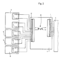
- the central connection point consists essentially of two elements, which are shown in Figures 2 and 3.
- FIG. 2 shows a connection module 11 for transmitting the signals generated by the additional devices to the control device 4. All signal lines of the additional devices 5, 6 and 7 are routed to a connecting bar 12. An emergency stop switch 13 is also provided on the reel sheeter, the lines of which also lead via the connection module 11. Between the terminal block 12 and the terminal block 14 are each optocouplers, which bring about a galvanic separation between the additional devices and the control device 4. An optocoupler is assigned to each connection pair. In The figure therefore shows an optocoupler 15 symbolically.
- connection module 16 which is arranged within the central connection point 10.
- This connection module transmits the output signals generated by the control device 4 to the additional devices. It includes a terminal block 17 to which the signal lines arriving from the control device 4 are connected. The signals routed via this terminal strip are fed to relay 18, the switching outputs of the relays being routed to the additional devices via a terminal strip 19.
- Through the central connection point 10 all lines between the control device and the additional devices are galvanically isolated and the electronic control is protected.
- optocouplers can be used for the output signals of the control device, just as the use of relays is possible for the input signals to the control device.
Landscapes
- Inking, Control Or Cleaning Of Printing Machines (AREA)
- Accessory Devices And Overall Control Thereof (AREA)
- Arrangements For Transmission Of Measured Signals (AREA)
- Record Information Processing For Printing (AREA)
Applications Claiming Priority (2)
| Application Number | Priority Date | Filing Date | Title |
|---|---|---|---|
| DE3843966 | 1988-12-24 | ||
| DE3843966A DE3843966A1 (de) | 1988-12-24 | 1988-12-24 | Einrichtung zum ankoppeln von zusatzgeraeten |
Publications (3)
| Publication Number | Publication Date |
|---|---|
| EP0375958A2 true EP0375958A2 (fr) | 1990-07-04 |
| EP0375958A3 EP0375958A3 (en) | 1990-12-05 |
| EP0375958B1 EP0375958B1 (fr) | 1994-03-16 |
Family
ID=6370313
Family Applications (1)
| Application Number | Title | Priority Date | Filing Date |
|---|---|---|---|
| EP89121858A Expired - Lifetime EP0375958B1 (fr) | 1988-12-24 | 1989-11-27 | Dispositif à relier les unités additionnelles |
Country Status (8)
| Country | Link |
|---|---|
| US (1) | US5287007A (fr) |
| EP (1) | EP0375958B1 (fr) |
| JP (1) | JPH02220847A (fr) |
| CN (1) | CN1013946B (fr) |
| AU (1) | AU631826B2 (fr) |
| CA (1) | CA2002129C (fr) |
| DE (2) | DE3843966A1 (fr) |
| ES (1) | ES2052869T3 (fr) |
Cited By (1)
| Publication number | Priority date | Publication date | Assignee | Title |
|---|---|---|---|---|
| EP0649744A1 (fr) * | 1993-09-29 | 1995-04-26 | BALDWIN GRAPHIC SYSTEMS, Inc. | Système pour contrôler une presse à imprimer, accessoires et auxiliaires destinés à celui-ci |
Families Citing this family (1)
| Publication number | Priority date | Publication date | Assignee | Title |
|---|---|---|---|---|
| DE10008221B4 (de) * | 2000-02-23 | 2008-02-21 | Man Roland Druckmaschinen Ag | Rotationsdruckmaschine, insbesondere Rollenrotationsoffsetdruckmaschine |
Family Cites Families (17)
| Publication number | Priority date | Publication date | Assignee | Title |
|---|---|---|---|---|
| US3678291A (en) * | 1970-05-18 | 1972-07-18 | Sci Systems Inc | Solid state relay |
| NL7306137A (fr) * | 1973-05-03 | 1974-11-05 | ||
| FR2409658A1 (fr) * | 1977-11-22 | 1979-06-15 | Lampes Sa | Rail d'alimentation a commande electronique |
| DE2822938C2 (de) * | 1978-05-26 | 1984-03-15 | WLW-Elektrotechnik GmbH & Co KG, 4150 Krefeld | Steuerungs- und Überwachungseinrichtung für eine aus mehreren Geräten bestehende elektrisch betriebene Anlage |
| DE2919087A1 (de) * | 1979-05-11 | 1980-11-13 | Rotaprint Gmbh | Druckmaschinensteuerung |
| DE3220803C2 (de) * | 1982-06-03 | 1994-03-10 | Heidelberger Druckmasch Ag | Farbdichtemeßanlage zur Ermittlung der Farbdichtewerte von Druckprodukten |
| JPS59194290A (ja) * | 1983-04-20 | 1984-11-05 | 株式会社リコー | 信号伝送方式 |
| JPS6010336U (ja) * | 1983-06-29 | 1985-01-24 | キヤノン電子株式会社 | インタ−フエ−ス回路装置 |
| DE3430338C2 (de) * | 1984-08-17 | 1987-03-26 | Nixdorf Computer Ag, 4790 Paderborn | Sendeschaltung für Signalübertragungssysteme |
| JPS6184251A (ja) * | 1984-10-03 | 1986-04-28 | Tokyo Kikai Seisakusho:Kk | 輪転機におけるプリセツト・システム |
| DD234831A1 (de) * | 1985-02-27 | 1986-04-16 | Polygraph Leipzig | Steuersystem fuer druckmaschinen |
| DE3614624A1 (de) * | 1986-04-30 | 1987-11-05 | Heidelberger Druckmasch Ag | Druckmaschine mit mehreren komponenten, insbesondere druckwerken, anlege- und auslegeeinrichtungen |
| DE3708925C2 (de) * | 1986-04-30 | 1995-08-31 | Heidelberger Druckmasch Ag | Einrichtung zur Steuerung oder Regelung von Betriebsvorgängen an einer Rotations-Offset-Bogendruckmaschine |
| DE3614979C3 (de) * | 1986-05-02 | 1999-12-16 | Heidelberger Druckmasch Ag | Sicherheitssystem für eine Druckmaschine |
| DE3615463A1 (de) * | 1986-05-07 | 1987-11-12 | Endress Hauser Gmbh Co | Anordnung zur signaluebertragung in einer messanordnung |
| DE3813590A1 (de) * | 1987-05-08 | 1988-11-17 | Hauni Werke Koerber & Co Kg | Werkzeugmaschine |
| US4889999A (en) * | 1988-09-26 | 1989-12-26 | Lutron Electronics Co., Inc. | Master electrical load control system |
-
1988
- 1988-12-24 DE DE3843966A patent/DE3843966A1/de not_active Ceased
-
1989
- 1989-11-02 CA CA002002129A patent/CA2002129C/fr not_active Expired - Fee Related
- 1989-11-27 EP EP89121858A patent/EP0375958B1/fr not_active Expired - Lifetime
- 1989-11-27 DE DE89121858T patent/DE58907237D1/de not_active Expired - Fee Related
- 1989-11-27 ES ES89121858T patent/ES2052869T3/es not_active Expired - Lifetime
- 1989-12-14 AU AU46734/89A patent/AU631826B2/en not_active Ceased
- 1989-12-15 CN CN89109136A patent/CN1013946B/zh not_active Expired
- 1989-12-21 JP JP1329769A patent/JPH02220847A/ja active Pending
- 1989-12-26 US US07/456,363 patent/US5287007A/en not_active Expired - Lifetime
Cited By (3)
| Publication number | Priority date | Publication date | Assignee | Title |
|---|---|---|---|---|
| EP0649744A1 (fr) * | 1993-09-29 | 1995-04-26 | BALDWIN GRAPHIC SYSTEMS, Inc. | Système pour contrôler une presse à imprimer, accessoires et auxiliaires destinés à celui-ci |
| CN1061302C (zh) * | 1993-09-29 | 2001-01-31 | 包德温图形系统有限公司 | 控制印刷机及其配件与辅助设备的系统 |
| US6373584B1 (en) | 1993-09-29 | 2002-04-16 | Baldwin Graphic Products | System for controlling printing press and accessories and auxiliaries therefor |
Also Published As
| Publication number | Publication date |
|---|---|
| AU4673489A (en) | 1990-06-28 |
| EP0375958B1 (fr) | 1994-03-16 |
| CA2002129A1 (fr) | 1990-06-24 |
| DE58907237D1 (de) | 1994-04-21 |
| CA2002129C (fr) | 1995-05-30 |
| EP0375958A3 (en) | 1990-12-05 |
| JPH02220847A (ja) | 1990-09-04 |
| US5287007A (en) | 1994-02-15 |
| AU631826B2 (en) | 1992-12-10 |
| CN1013946B (zh) | 1991-09-18 |
| ES2052869T3 (es) | 1994-07-16 |
| DE3843966A1 (de) | 1990-06-28 |
| CN1043665A (zh) | 1990-07-11 |
Similar Documents
| Publication | Publication Date | Title |
|---|---|---|
| DE3236812C2 (de) | Fernwirksystem | |
| EP0824231B2 (fr) | Système de fabrication | |
| EP0275992A2 (fr) | Parc machine avec plusieurs mobiles | |
| EP0884821A1 (fr) | Système de distribution d'énergie, en particulier pour un aéronef | |
| EP0344609A2 (fr) | Système de transmission numérique pour installations domestiques | |
| EP0772132A2 (fr) | Assemblage acteur/capteur pour le système technique de construction | |
| DE10357429B4 (de) | Modulare Bogenrotationsdruckmaschine | |
| DE69305383T2 (de) | Sensorverbindungssystem | |
| DE3900924A1 (de) | Vorrichtung und verfahren zum steuern mehrerer miteinander verbundener druckmaschinen | |
| DE3003641A1 (de) | Elektrisches steuer- oder anzeigesystem | |
| DE10148810B4 (de) | Steuerungs- und Energieversorgungssystem für wenigstens zwei Flugzeugsitze | |
| EP0943165A1 (fr) | Armoire electrique | |
| DE19543654A1 (de) | Verfahren und Vorrichtung zur Überwachung und Kontrolle einer Gerätekombination aus einem Hauptgerät und mindestens einem Zusatzgerät | |
| EP0205014A2 (fr) | Dispositif de surveillance | |
| DE19916894B4 (de) | Bussystem | |
| EP0375958B1 (fr) | Dispositif à relier les unités additionnelles | |
| DE4328932C2 (de) | Verfahren und Einrichtung für die Fernabfrage von Meßstellen | |
| DE10045651A1 (de) | Sicherheitsschaltgerät | |
| DE2828645A1 (de) | Einrichtung zur steuerung von mindestens zwei hydraulischen turbinen | |
| WO2008074609A2 (fr) | Appareil de terrain bifilaire pour la technique d'automatisation de procédés destinée à connecter au moins un élément de capteur | |
| BE1026797B1 (de) | Modulare Schaltvorrichtung zum Ansteuern wenigstens eines elektrischen Antriebs | |
| DE2822938C2 (de) | Steuerungs- und Überwachungseinrichtung für eine aus mehreren Geräten bestehende elektrisch betriebene Anlage | |
| EP1695158A1 (fr) | Dispositif de transmission de donnees a securite intrinseque | |
| DE19516418B4 (de) | Falzmaschinenverbund und Verfahren zum Betreiben eines Falzmaschinenverbunds | |
| DE3614624A1 (de) | Druckmaschine mit mehreren komponenten, insbesondere druckwerken, anlege- und auslegeeinrichtungen |
Legal Events
| Date | Code | Title | Description |
|---|---|---|---|
| PUAI | Public reference made under article 153(3) epc to a published international application that has entered the european phase |
Free format text: ORIGINAL CODE: 0009012 |
|
| 17P | Request for examination filed |
Effective date: 19891127 |
|
| AK | Designated contracting states |
Kind code of ref document: A2 Designated state(s): CH DE ES FR GB IT LI NL SE |
|
| PUAL | Search report despatched |
Free format text: ORIGINAL CODE: 0009013 |
|
| AK | Designated contracting states |
Kind code of ref document: A3 Designated state(s): CH DE ES FR GB IT LI NL SE |
|
| 17Q | First examination report despatched |
Effective date: 19920810 |
|
| GRAA | (expected) grant |
Free format text: ORIGINAL CODE: 0009210 |
|
| AK | Designated contracting states |
Kind code of ref document: B1 Designated state(s): CH DE ES FR GB IT LI NL SE |
|
| REF | Corresponds to: |
Ref document number: 58907237 Country of ref document: DE Date of ref document: 19940421 |
|
| ITF | It: translation for a ep patent filed | ||
| REG | Reference to a national code |
Ref country code: ES Ref legal event code: FG2A Ref document number: 2052869 Country of ref document: ES Kind code of ref document: T3 |
|
| GBT | Gb: translation of ep patent filed (gb section 77(6)(a)/1977) |
Effective date: 19940622 |
|
| ET | Fr: translation filed | ||
| PGFP | Annual fee paid to national office [announced via postgrant information from national office to epo] |
Ref country code: FR Payment date: 19941027 Year of fee payment: 6 |
|
| PGFP | Annual fee paid to national office [announced via postgrant information from national office to epo] |
Ref country code: SE Payment date: 19941107 Year of fee payment: 6 |
|
| PGFP | Annual fee paid to national office [announced via postgrant information from national office to epo] |
Ref country code: ES Payment date: 19941114 Year of fee payment: 6 |
|
| PGFP | Annual fee paid to national office [announced via postgrant information from national office to epo] |
Ref country code: NL Payment date: 19941130 Year of fee payment: 6 |
|
| PLBI | Opposition filed |
Free format text: ORIGINAL CODE: 0009260 |
|
| PGFP | Annual fee paid to national office [announced via postgrant information from national office to epo] |
Ref country code: CH Payment date: 19950120 Year of fee payment: 6 |
|
| EAL | Se: european patent in force in sweden |
Ref document number: 89121858.8 |
|
| 26 | Opposition filed |
Opponent name: KOENIG & BAUER AKTIENGESELLSCHAFT Effective date: 19941216 Opponent name: MAN ROLAND DRUCKMASCHINEN AG Effective date: 19941210 |
|
| NLR1 | Nl: opposition has been filed with the epo |
Opponent name: KOENIG & BAUER AG. Opponent name: MAN ROLAND DRUCKMASCHINEN AG. |
|
| PLBM | Termination of opposition procedure: date of legal effect published |
Free format text: ORIGINAL CODE: 0009276 |
|
| STAA | Information on the status of an ep patent application or granted ep patent |
Free format text: STATUS: OPPOSITION PROCEDURE CLOSED |
|
| PG25 | Lapsed in a contracting state [announced via postgrant information from national office to epo] |
Ref country code: SE Effective date: 19951128 Ref country code: ES Free format text: LAPSE BECAUSE OF NON-PAYMENT OF DUE FEES Effective date: 19951128 |
|
| PG25 | Lapsed in a contracting state [announced via postgrant information from national office to epo] |
Ref country code: LI Effective date: 19951130 Ref country code: CH Effective date: 19951130 |
|
| 27C | Opposition proceedings terminated |
Effective date: 19950814 |
|
| NLR2 | Nl: decision of opposition | ||
| PG25 | Lapsed in a contracting state [announced via postgrant information from national office to epo] |
Ref country code: NL Effective date: 19960601 |
|
| REG | Reference to a national code |
Ref country code: CH Ref legal event code: PL |
|
| PG25 | Lapsed in a contracting state [announced via postgrant information from national office to epo] |
Ref country code: FR Effective date: 19960731 |
|
| NLV4 | Nl: lapsed or anulled due to non-payment of the annual fee |
Effective date: 19960601 |
|
| EUG | Se: european patent has lapsed |
Ref document number: 89121858.8 |
|
| REG | Reference to a national code |
Ref country code: FR Ref legal event code: ST |
|
| REG | Reference to a national code |
Ref country code: ES Ref legal event code: FD2A Effective date: 20010503 |
|
| REG | Reference to a national code |
Ref country code: GB Ref legal event code: IF02 |
|
| PGFP | Annual fee paid to national office [announced via postgrant information from national office to epo] |
Ref country code: GB Payment date: 20031104 Year of fee payment: 15 |
|
| PG25 | Lapsed in a contracting state [announced via postgrant information from national office to epo] |
Ref country code: GB Free format text: LAPSE BECAUSE OF NON-PAYMENT OF DUE FEES Effective date: 20041127 |
|
| GBPC | Gb: european patent ceased through non-payment of renewal fee |
Effective date: 20041127 |
|
| PG25 | Lapsed in a contracting state [announced via postgrant information from national office to epo] |
Ref country code: IT Free format text: LAPSE BECAUSE OF NON-PAYMENT OF DUE FEES;WARNING: LAPSES OF ITALIAN PATENTS WITH EFFECTIVE DATE BEFORE 2007 MAY HAVE OCCURRED AT ANY TIME BEFORE 2007. THE CORRECT EFFECTIVE DATE MAY BE DIFFERENT FROM THE ONE RECORDED. Effective date: 20051127 |
|
| PGFP | Annual fee paid to national office [announced via postgrant information from national office to epo] |
Ref country code: DE Payment date: 20071122 Year of fee payment: 19 |
|
| PG25 | Lapsed in a contracting state [announced via postgrant information from national office to epo] |
Ref country code: DE Free format text: LAPSE BECAUSE OF NON-PAYMENT OF DUE FEES Effective date: 20090603 |