EP0376044A2 - Outil de carottage - Google Patents
Outil de carottage Download PDFInfo
- Publication number
- EP0376044A2 EP0376044A2 EP89122882A EP89122882A EP0376044A2 EP 0376044 A2 EP0376044 A2 EP 0376044A2 EP 89122882 A EP89122882 A EP 89122882A EP 89122882 A EP89122882 A EP 89122882A EP 0376044 A2 EP0376044 A2 EP 0376044A2
- Authority
- EP
- European Patent Office
- Prior art keywords
- locking
- drilling tool
- core drilling
- tube part
- adjusting
- Prior art date
- Legal status (The legal status is an assumption and is not a legal conclusion. Google has not performed a legal analysis and makes no representation as to the accuracy of the status listed.)
- Granted
Links
Images
Classifications
-
- E—FIXED CONSTRUCTIONS
- E21—EARTH OR ROCK DRILLING; MINING
- E21B—EARTH OR ROCK DRILLING; OBTAINING OIL, GAS, WATER, SOLUBLE OR MELTABLE MATERIALS OR A SLURRY OF MINERALS FROM WELLS
- E21B25/00—Apparatus for obtaining or removing undisturbed cores, e.g. core barrels or core extractors
Definitions
- the invention relates to a core drilling tool according to the preamble of claim 1.
- the conical adjusting thread of the adjusting device also forms the connecting thread for supporting the inner unit in the outer housing.
- a tubular extension of the indoor unit with axial locking grooves is provided on its outside, into which locking claws projecting inwards from above by a cylindrical locking element can be inserted, which at the same time project over the lower edge of the locking part and into slots in a lower shoulder of an expanded inner bore of the outer housing can be used.
- the outer housing is screwed on at a separation point located close above the adjusting device, after which the inner unit can be rotated and axially adjusted with the aid of a key inserted into the lower tool part from above and can be brought into engagement with the inner unit and after the lock has been released.
- Adjustment movements in this version require a high torque on the key, because the full weight of the inner element rests on the flat threads of the adjusting thread.
- This includes adjusting heavy indoor units, such as those with long inner tubes practice.
- the setting device is arranged in a concealed manner during setting processes and cannot be checked visually, also for functionality.
- the design of the adjusting device as a separate intermediate unit creates an adjustment possibility which is independent of the suspension of the indoor unit in the outer housing and which can also be implemented retrospectively for core drilling tools of any design.
- the upper outer housing part together with the inner unit can be pulled open a bit, thereby exposing the inner part of the intermediate unit for an optical inspection during the adjustment process and intercepting it below the adjusting thread for weight relief.
- settings can be made precisely and over a large adjustment range with little effort, which is particularly important in the case of very long inner tubes and / or those made of special materials such as plastic or aluminum.
- the adjusting device can be individually adapted to the core drilling tool in which it is used and is adaptable in this way solution independent of other functions such as the support in the outer housing.
- the intermediate unit can be used at any suitable position between the connection point of the inner unit and the bearing device for the inner tube, so that the application of the invention is not restricted to special designs of core drilling tools, but is possible with all core drilling tools that have an outer housing and an in supported indoor unit.
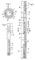
- the tubular outer casing 2 is provided at its lower end with a core bit 5, e.g. screwed.
- an inner unit designated as a whole as 6, which is supported at its upper end at a connection point 7 in the outer housing, for example by being screwed to it.
- the inner unit 6 can be pulled up as a whole and a suitable support is provided.
- the inner unit 6 comprises, as the lower component, an inner tube 8 receiving a drilled core, which is mounted freely rotatable about its central axis and thus the main tool axis 10 relative to the upper component of the inner unit 6 by means of a bearing device 9.
- a bearing device 9 In the section of the core drilling tool 1, designated II in FIG. 1, there is an adjusting device 11 which is illustrated schematically in more detail in FIGS. 2 and 3 and which is designed as a separate intermediate unit.
- the adjusting device 11 inserted into the core drilling tool 1 at a suitable point between the connection point 7 for the inner unit 6 and the bearing device 9 for the inner tube 8 comprises in particular an outer part 12 which can be inserted into the outer housing 2 and which is designed as a spacer tube and between the adjacent parts of the outer housing 2 is screwed in between, and an inner part 13.
- This has an upper adjusting tube part 14 with an external thread 15 along its lower main part and with an external thread 16 at its upper end and a lower adjusting tube part 17, which is provided with an internal thread 18 at least in its upper region .
- External threads 15 and internal threads 18 of the adjusting tube parts 14, 15 which are in screw engagement with one another form an adjusting thread which enables an axial adjustment of one adjusting tube part 14 relative to the other adjusting tube part 17.
- the upper adjusting tube part 14 has, along its main part provided with the outer housing 15, axial locking grooves 19 which intersect with the external thread 15, two of which are provided in a diametrical arrangement.
- the lower adjusting tube part 17 is also provided on the outside of its upper region with axial locking grooves 20, preferably with four locking grooves 20 arranged diametrically in pairs.
- a lock nut 21 is screwed, and below the lock nut 21 there is a locking element 22, which is designed as an annular body, is displaceable along the external thread 15 of the upper control tube part 14 and with inward, provided at the upper end locking claws 23 in the locking grooves 19 of the upper adjusting tube part 14 engages.
- the locking element 22 comes into engagement with the locking grooves 20 of the lower actuating tube part 17 from above in the transition into its locking position, so that in the locking position of the locking element 22 the upper and the lower adjusting tube part 14, 17 against rotational movements are secured. In this locking position illustrated in FIG. 2, the locking element 22 is secured against an upward movement by the locking nut 21.
- Markings 25 can be provided in the locking grooves 19 of the upper adjusting tube part 14, which make it possible to control the extent of the adjustments provided by measuring the distance between the top of the locking nut 21 and the markings 25.
- a gap of the desired dimension e.g. of 4 mm, can be set or restored, which ensures the passage of drilling fluid.
- the outer housing 2 in the area below the upper end of the spacer tube 12, for example in the rotary table of a drilling tower, intercepted and its screw connection with the upper part of the outer housing 2 loosened. Then the upper part of the core drilling tool 1 together with the internal unit 6 is pulled up a little until the adjusting device 11 is exposed. In the area below the adjusting thread 15, 18, the internal unit 6 is then intercepted with respect to the fixed lower tool part, thereby relieving the weight of the adjusting thread 15, 18. Then the lock nut 21 is screwed up along the external thread 15 of the upper adjusting tube part 14, the locking element 22 is pushed up axially and brought out of locking engagement.
- the desired adjustment or adjustment is then carried out by screwing the upper adjusting tube part 14 with respect to the lower adjusting tube part 17. Then the locking element 22 is moved back into its locking position and the lock nut 21 is screwed down until the locking element 22 is firmly pressed against the upper end of the lower control tube part 17. After lowering the upper tool part, the outer housing 2 can then be screwed together again, after which the core drilling tool with an adjusted gap between the end of the core tube 8 and the core drilling bit 5 is ready for operation.
Landscapes
- Geology (AREA)
- Life Sciences & Earth Sciences (AREA)
- Engineering & Computer Science (AREA)
- Mining & Mineral Resources (AREA)
- Environmental & Geological Engineering (AREA)
- Fluid Mechanics (AREA)
- Physics & Mathematics (AREA)
- General Life Sciences & Earth Sciences (AREA)
- Geochemistry & Mineralogy (AREA)
- Earth Drilling (AREA)
- Processing Of Stones Or Stones Resemblance Materials (AREA)
- Drilling Tools (AREA)
- Drilling And Boring (AREA)
Applications Claiming Priority (2)
| Application Number | Priority Date | Filing Date | Title |
|---|---|---|---|
| DE3843800 | 1988-12-24 | ||
| DE3843800A DE3843800C1 (fr) | 1988-12-24 | 1988-12-24 |
Publications (3)
| Publication Number | Publication Date |
|---|---|
| EP0376044A2 true EP0376044A2 (fr) | 1990-07-04 |
| EP0376044A3 EP0376044A3 (fr) | 1992-02-26 |
| EP0376044B1 EP0376044B1 (fr) | 1995-07-19 |
Family
ID=6370193
Family Applications (1)
| Application Number | Title | Priority Date | Filing Date |
|---|---|---|---|
| EP89122882A Expired - Lifetime EP0376044B1 (fr) | 1988-12-24 | 1989-12-12 | Outil de carottage |
Country Status (5)
| Country | Link |
|---|---|
| US (1) | US5025872A (fr) |
| EP (1) | EP0376044B1 (fr) |
| CA (1) | CA2006607C (fr) |
| DE (1) | DE3843800C1 (fr) |
| NO (1) | NO895214L (fr) |
Families Citing this family (5)
| Publication number | Priority date | Publication date | Assignee | Title |
|---|---|---|---|---|
| US6729416B2 (en) | 2001-04-11 | 2004-05-04 | Schlumberger Technology Corporation | Method and apparatus for retaining a core sample within a coring tool |
| US7431107B2 (en) * | 2003-01-22 | 2008-10-07 | Schlumberger Technology Corporation | Coring bit with uncoupled sleeve |
| US20050133267A1 (en) * | 2003-12-18 | 2005-06-23 | Schlumberger Technology Corporation | [coring tool with retention device] |
| US8613330B2 (en) | 2011-07-05 | 2013-12-24 | Schlumberger Technology Corporation | Coring tools and related methods |
| CN102787818B (zh) * | 2012-08-30 | 2015-08-19 | 刘力强 | 小型电动地质取芯钻机 |
Family Cites Families (6)
| Publication number | Priority date | Publication date | Assignee | Title |
|---|---|---|---|---|
| DE1039006B (de) * | 1954-11-17 | 1958-09-18 | Helmut Huegel Dr Ing | Kernfangvorrichtung fuer Tiefbohrwerkzeuge |
| DE1185554B (de) * | 1963-06-21 | 1965-01-21 | Roland Joseph Du Berger | Kernrohr |
| US4300643A (en) * | 1979-03-22 | 1981-11-17 | Diamant Boart | Double core barrel |
| US4463460A (en) * | 1982-08-13 | 1984-08-07 | Indiana Brass, Inc. | Roman tub fixture |
| US4553613A (en) * | 1983-09-09 | 1985-11-19 | Norton Christensen, Inc. | Hydraulic lift inner barrel in a drill string coring tool |
| US4580643A (en) * | 1984-09-10 | 1986-04-08 | Norton Christensen, Inc. | Adjustable bearing section core barrel |
-
1988
- 1988-12-24 DE DE3843800A patent/DE3843800C1/de not_active Expired - Lifetime
-
1989
- 1989-12-12 EP EP89122882A patent/EP0376044B1/fr not_active Expired - Lifetime
- 1989-12-15 US US07/451,090 patent/US5025872A/en not_active Expired - Lifetime
- 1989-12-22 NO NO89895214A patent/NO895214L/no unknown
- 1989-12-22 CA CA002006607A patent/CA2006607C/fr not_active Expired - Fee Related
Also Published As
| Publication number | Publication date |
|---|---|
| US5025872A (en) | 1991-06-25 |
| NO895214D0 (no) | 1989-12-22 |
| CA2006607C (fr) | 1997-02-11 |
| EP0376044B1 (fr) | 1995-07-19 |
| DE3843800C1 (fr) | 1990-04-12 |
| NO895214L (no) | 1990-06-25 |
| CA2006607A1 (fr) | 1990-06-24 |
| EP0376044A3 (fr) | 1992-02-26 |
Similar Documents
| Publication | Publication Date | Title |
|---|---|---|
| EP0541904B1 (fr) | Table, en particulier pour la préparation et le soudage | |
| DE69510680T2 (de) | Bohrwerkzeug | |
| DE4101438A1 (de) | Spindeladapter fuer werkzeughalter mit werkzeugeinstellsteuerung | |
| DE1928490B2 (de) | Schloßmutter | |
| DE10216003A1 (de) | Dockingvorrichtung | |
| DE60025623T2 (de) | Bohrmeisselverbinder | |
| EP0376044B1 (fr) | Outil de carottage | |
| DE102010033977A1 (de) | Mastbefestigung für Straßenleuchte | |
| DE3135964C2 (fr) | ||
| DE2828812C2 (de) | Spannvorrichtung zum Festspannen von Werkstücken auf dem Werktisch einer Werkzeugmaschine | |
| DE2405304C2 (de) | Richtstift | |
| DE10338610A1 (de) | Schnittstelle | |
| DE4424765C2 (de) | Vorrichtung zum in der Höhe stufenlosen Verstellen von zu fixierenden Werkstücken | |
| DE20204107U1 (de) | Spannwerkzeug | |
| DE3215794C2 (de) | Spannvorrichtung | |
| DE3744693A1 (de) | Ventilanbohrschelle | |
| DE8910822U1 (de) | Mit der Arbeitsspindel einer handgeführten Elektrowerkzeugmaschine vereinigbarer Adapter | |
| DE3832602C2 (de) | Stopfen zum Abdichten von Versorgungsleitungen und Werkzeug zu seinem Einsetzen | |
| DE573527C (de) | Erdbohrer, bei welchem ein Rollenschneider auf seiner Spindel durch Verriegelungsorgane gehalten wird | |
| CH680089A5 (en) | Holder for measurement probe - comprises axially displaceable protective tube retained by cylindrical spiral spring | |
| DE2459543A1 (de) | Laengenverstellbare steuerstange zur rotorblatt-einstellung | |
| EP0915219A1 (fr) | Support de poteau | |
| DE2920519C2 (fr) | ||
| CH640052A5 (en) | Dual bubble level | |
| DE1500852C3 (de) | Klemmvorrichtungen für Bohrgestänge oder Rohre |
Legal Events
| Date | Code | Title | Description |
|---|---|---|---|
| PUAI | Public reference made under article 153(3) epc to a published international application that has entered the european phase |
Free format text: ORIGINAL CODE: 0009012 |
|
| AK | Designated contracting states |
Kind code of ref document: A2 Designated state(s): BE FR GB NL |
|
| PUAL | Search report despatched |
Free format text: ORIGINAL CODE: 0009013 |
|
| AK | Designated contracting states |
Kind code of ref document: A3 Designated state(s): BE FR GB NL |
|
| 17P | Request for examination filed |
Effective date: 19920814 |
|
| RAP1 | Party data changed (applicant data changed or rights of an application transferred) |
Owner name: EASTMAN TELECO COMPANY |
|
| 17Q | First examination report despatched |
Effective date: 19931018 |
|
| GRAA | (expected) grant |
Free format text: ORIGINAL CODE: 0009210 |
|
| AK | Designated contracting states |
Kind code of ref document: B1 Designated state(s): BE FR GB NL |
|
| GBT | Gb: translation of ep patent filed (gb section 77(6)(a)/1977) |
Effective date: 19950814 |
|
| ET | Fr: translation filed | ||
| PLBE | No opposition filed within time limit |
Free format text: ORIGINAL CODE: 0009261 |
|
| STAA | Information on the status of an ep patent application or granted ep patent |
Free format text: STATUS: NO OPPOSITION FILED WITHIN TIME LIMIT |
|
| 26N | No opposition filed | ||
| PGFP | Annual fee paid to national office [announced via postgrant information from national office to epo] |
Ref country code: FR Payment date: 19961115 Year of fee payment: 8 |
|
| PGFP | Annual fee paid to national office [announced via postgrant information from national office to epo] |
Ref country code: NL Payment date: 19961120 Year of fee payment: 8 |
|
| PGFP | Annual fee paid to national office [announced via postgrant information from national office to epo] |
Ref country code: BE Payment date: 19961126 Year of fee payment: 8 |
|
| PG25 | Lapsed in a contracting state [announced via postgrant information from national office to epo] |
Ref country code: FR Free format text: THE PATENT HAS BEEN ANNULLED BY A DECISION OF A NATIONAL AUTHORITY Effective date: 19971231 Ref country code: BE Free format text: LAPSE BECAUSE OF NON-PAYMENT OF DUE FEES Effective date: 19971231 |
|
| BERE | Be: lapsed |
Owner name: EASTMAN TELECO CY Effective date: 19971231 |
|
| PG25 | Lapsed in a contracting state [announced via postgrant information from national office to epo] |
Ref country code: NL Free format text: LAPSE BECAUSE OF NON-PAYMENT OF DUE FEES Effective date: 19980701 |
|
| NLV4 | Nl: lapsed or anulled due to non-payment of the annual fee |
Effective date: 19980701 |
|
| REG | Reference to a national code |
Ref country code: FR Ref legal event code: ST |
|
| PGFP | Annual fee paid to national office [announced via postgrant information from national office to epo] |
Ref country code: GB Payment date: 19981119 Year of fee payment: 10 |
|
| PG25 | Lapsed in a contracting state [announced via postgrant information from national office to epo] |
Ref country code: GB Free format text: LAPSE BECAUSE OF NON-PAYMENT OF DUE FEES Effective date: 19991212 |
|
| GBPC | Gb: european patent ceased through non-payment of renewal fee |
Effective date: 19991212 |