EP0376204A2 - Einstellbare Bohrstangeneinsatzpatrone - Google Patents
Einstellbare Bohrstangeneinsatzpatrone Download PDFInfo
- Publication number
- EP0376204A2 EP0376204A2 EP89123805A EP89123805A EP0376204A2 EP 0376204 A2 EP0376204 A2 EP 0376204A2 EP 89123805 A EP89123805 A EP 89123805A EP 89123805 A EP89123805 A EP 89123805A EP 0376204 A2 EP0376204 A2 EP 0376204A2
- Authority
- EP
- European Patent Office
- Prior art keywords
- anvil
- cartridge
- recess
- screw
- boring bar
- Prior art date
- Legal status (The legal status is an assumption and is not a legal conclusion. Google has not performed a legal analysis and makes no representation as to the accuracy of the status listed.)
- Granted
Links
Images

Classifications
-
- B—PERFORMING OPERATIONS; TRANSPORTING
- B23—MACHINE TOOLS; METAL-WORKING NOT OTHERWISE PROVIDED FOR
- B23B—TURNING; BORING
- B23B29/00—Holders for non-rotary cutting tools; Boring bars or boring heads; Accessories for tool holders
- B23B29/03—Boring heads
- B23B29/034—Boring heads with tools moving radially, e.g. for making chamfers or undercuttings
- B23B29/03403—Boring heads with tools moving radially, e.g. for making chamfers or undercuttings radially adjustable before starting manufacturing
- B23B29/03421—Boring heads with tools moving radially, e.g. for making chamfers or undercuttings radially adjustable before starting manufacturing by pivoting the tool carriers or by elastic deformation
-
- Y—GENERAL TAGGING OF NEW TECHNOLOGICAL DEVELOPMENTS; GENERAL TAGGING OF CROSS-SECTIONAL TECHNOLOGIES SPANNING OVER SEVERAL SECTIONS OF THE IPC; TECHNICAL SUBJECTS COVERED BY FORMER USPC CROSS-REFERENCE ART COLLECTIONS [XRACs] AND DIGESTS
- Y10—TECHNICAL SUBJECTS COVERED BY FORMER USPC
- Y10T—TECHNICAL SUBJECTS COVERED BY FORMER US CLASSIFICATION
- Y10T407/00—Cutters, for shaping
- Y10T407/19—Rotary cutting tool
- Y10T407/1906—Rotary cutting tool including holder [i.e., head] having seat for inserted tool
- Y10T407/1928—Tool adjustable relative to holder
- Y10T407/193—Radially
-
- Y—GENERAL TAGGING OF NEW TECHNOLOGICAL DEVELOPMENTS; GENERAL TAGGING OF CROSS-SECTIONAL TECHNOLOGIES SPANNING OVER SEVERAL SECTIONS OF THE IPC; TECHNICAL SUBJECTS COVERED BY FORMER USPC CROSS-REFERENCE ART COLLECTIONS [XRACs] AND DIGESTS
- Y10—TECHNICAL SUBJECTS COVERED BY FORMER USPC
- Y10T—TECHNICAL SUBJECTS COVERED BY FORMER US CLASSIFICATION
- Y10T407/00—Cutters, for shaping
- Y10T407/19—Rotary cutting tool
- Y10T407/1906—Rotary cutting tool including holder [i.e., head] having seat for inserted tool
- Y10T407/1932—Rotary cutting tool including holder [i.e., head] having seat for inserted tool with means to fasten tool seat to holder
-
- Y—GENERAL TAGGING OF NEW TECHNOLOGICAL DEVELOPMENTS; GENERAL TAGGING OF CROSS-SECTIONAL TECHNOLOGIES SPANNING OVER SEVERAL SECTIONS OF THE IPC; TECHNICAL SUBJECTS COVERED BY FORMER USPC CROSS-REFERENCE ART COLLECTIONS [XRACs] AND DIGESTS
- Y10—TECHNICAL SUBJECTS COVERED BY FORMER USPC
- Y10T—TECHNICAL SUBJECTS COVERED BY FORMER US CLASSIFICATION
- Y10T408/00—Cutting by use of rotating axially moving tool
- Y10T408/83—Tool-support with means to move Tool relative to tool-support
- Y10T408/85—Tool-support with means to move Tool relative to tool-support to move radially
- Y10T408/858—Moving means including wedge, screw or cam
- Y10T408/8583—Moving means including wedge, screw or cam with resiliently urged Tool
- Y10T408/85837—Moving means including wedge, screw or cam with resiliently urged Tool with spring retainer
-
- Y—GENERAL TAGGING OF NEW TECHNOLOGICAL DEVELOPMENTS; GENERAL TAGGING OF CROSS-SECTIONAL TECHNOLOGIES SPANNING OVER SEVERAL SECTIONS OF THE IPC; TECHNICAL SUBJECTS COVERED BY FORMER USPC CROSS-REFERENCE ART COLLECTIONS [XRACs] AND DIGESTS
- Y10—TECHNICAL SUBJECTS COVERED BY FORMER USPC
- Y10T—TECHNICAL SUBJECTS COVERED BY FORMER US CLASSIFICATION
- Y10T408/00—Cutting by use of rotating axially moving tool
- Y10T408/83—Tool-support with means to move Tool relative to tool-support
- Y10T408/85—Tool-support with means to move Tool relative to tool-support to move radially
- Y10T408/858—Moving means including wedge, screw or cam
- Y10T408/8583—Moving means including wedge, screw or cam with resiliently urged Tool
- Y10T408/85843—Resilient Tool or tool-support
-
- Y—GENERAL TAGGING OF NEW TECHNOLOGICAL DEVELOPMENTS; GENERAL TAGGING OF CROSS-SECTIONAL TECHNOLOGIES SPANNING OVER SEVERAL SECTIONS OF THE IPC; TECHNICAL SUBJECTS COVERED BY FORMER USPC CROSS-REFERENCE ART COLLECTIONS [XRACs] AND DIGESTS
- Y10—TECHNICAL SUBJECTS COVERED BY FORMER USPC
- Y10T—TECHNICAL SUBJECTS COVERED BY FORMER US CLASSIFICATION
- Y10T408/00—Cutting by use of rotating axially moving tool
- Y10T408/83—Tool-support with means to move Tool relative to tool-support
- Y10T408/85—Tool-support with means to move Tool relative to tool-support to move radially
- Y10T408/858—Moving means including wedge, screw or cam
- Y10T408/8595—Pivotable tool-support
-
- Y—GENERAL TAGGING OF NEW TECHNOLOGICAL DEVELOPMENTS; GENERAL TAGGING OF CROSS-SECTIONAL TECHNOLOGIES SPANNING OVER SEVERAL SECTIONS OF THE IPC; TECHNICAL SUBJECTS COVERED BY FORMER USPC CROSS-REFERENCE ART COLLECTIONS [XRACs] AND DIGESTS
- Y10—TECHNICAL SUBJECTS COVERED BY FORMER USPC
- Y10T—TECHNICAL SUBJECTS COVERED BY FORMER US CLASSIFICATION
- Y10T408/00—Cutting by use of rotating axially moving tool
- Y10T408/86—Tool-support with means to permit positioning of the Tool relative to support
- Y10T408/865—Pivotable Tool
Definitions
- the present invention relates to the field of machining tools such as boring bars and more particularly to boring bars with adjustable insert cartridges.
- the boring bar includes a slotted area with an arcuate bottom face on which a correspondingly shaped surface of an anvil is seated.
- the boring bar also includes means for causing the anvil to slide upon a radiused surface of the boring bar and to rotate the anvil and cutting insert affixed thereto relative to the boring bar.
- Cartridges which provide adjustment for cutting inserts are known.
- U.S. Patent No. 3,885,282 to Pataky describes a machining tool including a holder and insert to which a cutting tool can be attached.
- the insert is rotatably mounted in a recess in the holder and fixed in a desired position relative to the holder by a locking screw. Rotatable adjustment of the insert allows for the altering of the tip working angle.
- U.S. Patent No. 4,631,994 to Jester et al a linearly and angularly adjustable holder for a cutting tool is provided.
- Such tool permits pivotal adjustment by means of an adjustment screw having a threaded portion seated in a basic element and a head which engages a recess in a rotatably mounted receptacle element which holds a cutting tool insert. Rotation of the adjustment screw causes rotation of the receptacle element.
- the structure described in these patents is not directed to alleviating the problem of "stacked" tolerances as described herein.
- high speed boring bars cannot meet the precision cutting parameters required today with traditional cartridges mounted to the periphery of the boring bar due to the chatter created. Although creating a recess large enough to seat the cartridge within the bar may stablize the bar, radial adjustment where the adjustment force is directed against the bar would still induce bowing in narrow diameter boring bars.
- the boring bar has a longitudinally oriented slot or recess with planar parallel walls which are spaced by the width of an arcuate seating surface.
- the seating surface intersects with the walls and opens radially to the periphery of the boring bar.
- the cartridge includes an anvil with a top face and a radiused bottom face.
- the top face includes a recessed pocket for receipt of an indexable insert, positioned between forward and rear portions.
- the radiused face of the anvil extends between the forward and rear portions and when seated within the slot abut against the corresponding radiused face.
- the forward and rear portions are recessed for receipt of means for preloading the anvil in said arcuate seat and means for adjusting the anvil along the arcuate seat respectively.
- the insert is positioned on the anvil axially spaced from its rotational center of the anvil such that fine adjustment may be accomplished and such that loading resulting from cutting operations is principally transferred to the bar and to rotating the anvil in the bar against the adjusting means rather than the preload means.
- An advantage being that the resilient preloading means is removed from the loading action allowing precision adjustment and minimizing chatter.
- Another advantage is that an indexable insert and adjustable cartridge is provided in a boring bar without removing of a large portion of bar stock thereby maintaining tool strength.
- a further advantage is that the rotation of the anvil in the boring bar eliminates the need for adjustment means which load the boring bar to the extent of inducing bowing in small diameter bars.
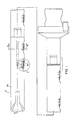
- a boring bar 10 is provided for rotation about a longitudinally disposed axis 15.
- Boring bar 10 as is known in the art is of cylindrical form having a periphery 20.
- each recess 25 includes parallel walls 30 joined at an arcuate seating surface 35 which opens radially towards the periphery 20.
- the cartridge 40 od Figure 2 comprises an anvil 43 which is generally an elongated piece of hardened tool steel having a uniform width and an axial dimension corresponding to the particular recess 25 selected.
- the cartridge 40 further includes a radiused lower surface 45 which corresponds to the arcuate surface 35 to allow for axial rotation in the clockwise direction as indicated by arrow 50 or counterclockwise direction as illustrated by arrow 55.
- anvil 43 further includes a top face 57 radially spaced from lower surface 45 and at least one pocket 60 for receipt of lay down indexable insert 65.
- the pocket has at least two abutment walls 70 which intersect with a seating face 75.
- Seating face 75 includes an aperture 80 tapped to provide secure retention for an insert retaining screw 85.
- top face 57 includes axially spaced forward 90 and rear portions 95 separated by insert 65.
- Arcuate lower surface 45 extends from the forward 90 to rear 95 potions.
- the rear portion 95 includes a first recessed area 100 which communicates motion from means for adjusting the cartridge and inducing counterclockwise rotation in the direction of arrow 55 radially adjusting the insert 65.
- the range of adjustment is at least as much as the total "stacked" manufacturing tolerances of cartridge 40 and bar 10
- a range of adjustment through adjustment means 105 of as much as .020 inches is preferred.
- adjusting means 105 comprises an arcuate headed screw 110 threaded in the boring bar 10 and abutting a conical face 47 of the first recessed area 100 to provide camming force to the anvil 43.
- a right hand screw thread is desired with a fine pitch and in particular with 32 threads per inch.
- a securing screw 48 for preventing rotation of screw 110, traverses aperture 112 and forces a soft metal shoe 113 against screw 110.
- Other embodiments including direct seating on flat areas of screw 110 will be apparent to those skilled in the art. Those skilled in the art will recognize that other embodiments are also apparent such as the use of a clamp.
- the forward portion 90 includes a second recess area 115 and aperture 120 which traverses anvil 43.
- Means for preloading the anvil 43 in recess 25 during adjustment is provided in one embodiment of the present invention as illustrated in Figure 2.
- Screw 125 traps spring washers 130 in second recessed area 115 and threads into body 10 compressing the spring washers against the anvil to provide a resilient preloading force.
- the present invention also contemplates the use of screw 125 without washers 130.
- Lay-down inserts 65 comprise generally a wafer of hardened material such as tungsten carbide, ceramics, cermets or sialons to name a few.
- the desired material is dependent on the type of application and the boring parameters. For example, on a 2 1/8 inch boring bar about 32 inches in length and employing five adjustment cartridges as claimed and disclosed herein, 3/8 wide by .460 inch parallelogram shaped inserts available from GTE Valenite Modco using tungsten carbide grade VC-2 are employed for soft and abrasive materials such as cast iron. For boring applications in carbon steel, carbide grade VC-5 is available.
- various positive radial and negative axial rakes are contemplated depending on the application.
- insert 65 and insert pocket 60 on top face 57 is important to obtaining the above disclosed range of adjustment.
- anvil 43 when rotated within recess 25 in the direction of arrows 50 or 55, rotates about center 140 when unrestricted by the preloading or adjustment means discussed above.
- Positioning pocket 60 and insert 65 axially from center 140 toward forward portion 90 results in a decreasing range of adjustment the closer the pocket is placed to center 140.
- the exact position of the pocket 60 in anvil 43 depends in part on the size of the insert and anvil, it is generally known to those of skill in the art that loading during operation is absorbed by the boring bar rather than preloading means or adjusting means the closer the pocket 60 is placed to center 140. This results in reduced cartridge chatter and wear on the adjustment means.
- the present invention in at least one embodiment contemplates a plurality of tapped apertures 145 which traverse boring bar 10 in a direction generally normal to the recess walls 30 and which open to the boring bar periphery 20 to provide access to an operator.
- Screws 150 threaded to travel within apertures 145 are are rotated into secure abutment with anvil 43, forcing the anvil against one of the pair of parallel recess walls 30.
- the screws are made of a resilient material such as neoprene or hardened materials such as steel.
Landscapes
- Engineering & Computer Science (AREA)
- Mechanical Engineering (AREA)
- Cutting Tools, Boring Holders, And Turrets (AREA)
- Drilling And Boring (AREA)
Applications Claiming Priority (2)
| Application Number | Priority Date | Filing Date | Title |
|---|---|---|---|
| US290600 | 1988-12-27 | ||
| US07/290,600 US4927301A (en) | 1988-12-27 | 1988-12-27 | Adjustable boring bar cartridge |
Publications (3)
| Publication Number | Publication Date |
|---|---|
| EP0376204A2 true EP0376204A2 (de) | 1990-07-04 |
| EP0376204A3 EP0376204A3 (de) | 1991-01-30 |
| EP0376204B1 EP0376204B1 (de) | 1994-09-14 |
Family
ID=23116733
Family Applications (1)
| Application Number | Title | Priority Date | Filing Date |
|---|---|---|---|
| EP89123805A Expired - Lifetime EP0376204B1 (de) | 1988-12-27 | 1989-12-22 | Einstellbare Bohrstangeneinsatzpatrone |
Country Status (4)
| Country | Link |
|---|---|
| US (1) | US4927301A (de) |
| EP (1) | EP0376204B1 (de) |
| JP (1) | JP2930632B2 (de) |
| DE (1) | DE68918254T2 (de) |
Cited By (3)
| Publication number | Priority date | Publication date | Assignee | Title |
|---|---|---|---|---|
| WO2008121055A1 (en) * | 2007-03-30 | 2008-10-09 | Seco Tools Ab | Cutting tool with replaceable insert supporting cassette |
| US8007207B2 (en) | 2007-03-30 | 2011-08-30 | Seco Tools Ab | Cutting tool with replaceable insert supporting cassette |
| EP3532228A1 (de) * | 2016-10-26 | 2019-09-04 | Schmidt + Clemens GmbH & Co. KG | Tieflochbohrverfahren, werkzeug für eine tieflochbohrmaschine, tieflochbohrmaschine, und schleudergussrohr |
Families Citing this family (22)
| Publication number | Priority date | Publication date | Assignee | Title |
|---|---|---|---|---|
| EP0556422A1 (de) * | 1991-02-11 | 1993-08-25 | Valenite Inc. | Verbesserte einstellbare Bohrstange |
| US5147157A (en) * | 1991-08-07 | 1992-09-15 | Gte Valenite Corporation | Adjustable leaf spring cartridge for face mills |
| US5156501A (en) * | 1991-08-07 | 1992-10-20 | Gte Valenite Corporation | Adjustable torsion bar cartridge for face mills |
| US5336026A (en) * | 1992-12-21 | 1994-08-09 | Valenite Inc. | Adjustable boring bar |
| US5320458A (en) * | 1993-05-24 | 1994-06-14 | Valenite Inc. | Cutting tool having a cutter cartridge adjustable around two adjustment axes |
| US5913643A (en) * | 1997-04-22 | 1999-06-22 | Kennametal Inc. | Adjustable lead angle chamfering toolholder |
| US7029209B2 (en) * | 2000-12-18 | 2006-04-18 | Cardemon, Inc. | Slidable boring tool with fine adjustment |
| BR0116267A (pt) * | 2000-12-18 | 2004-01-06 | Cardemon Inc Dba Car Tec Co | Método e aparelho de ajuste para uma ferramenta de perfuração |
| MXPA04010576A (es) * | 2002-04-25 | 2005-07-01 | Cardemon Inc | Herramienta perforadora deslizable con ajuste fino. |
| US6702526B2 (en) * | 2002-04-29 | 2004-03-09 | Kennametal Inc. | Cutting tool |
| US6808340B2 (en) | 2002-09-06 | 2004-10-26 | Prototype Productions, Inc. | Tool apparatus |
| DE202004008642U1 (de) * | 2004-05-27 | 2005-09-29 | Kennametal Inc. | Fräswerkzeug |
| SE528432C2 (sv) * | 2004-11-05 | 2006-11-14 | Seco Tools Ab | Med aluminiumoxid belagt skärverktygsskär samt metod för att framställa detta |
| SE528430C2 (sv) * | 2004-11-05 | 2006-11-14 | Seco Tools Ab | Med aluminiumoxid belagt skärverktygsskär samt metod att framställa detta |
| SE528431C2 (sv) * | 2004-11-05 | 2006-11-14 | Seco Tools Ab | Med aluminiumoxid belagt skärverktygsskär samt metod att framställa detta |
| SE528820C2 (sv) * | 2004-12-14 | 2007-02-20 | Seco Tools Ab | Borrningsverktyg med justerbar kassett |
| CN101091995B (zh) * | 2006-06-23 | 2012-05-23 | 德州德隆(集团)机床有限责任公司 | 深孔组合镗滚头 |
| US8469639B2 (en) * | 2007-05-31 | 2013-06-25 | Valenite, Llc | Actuated material removal tool |
| US9050657B2 (en) * | 2007-07-05 | 2015-06-09 | Sandvik, Inc. | Actuated material removal tool |
| US7735401B2 (en) * | 2008-07-16 | 2010-06-15 | Dimitrije Stojanovski | Boring tool with adjustable chamfer cutter |
| DE102012004654A1 (de) * | 2011-03-29 | 2012-10-04 | Kennametal India Limited | Schneideinheit, Verfahren zur Änderung des Spanwinkels der Schneideinheit und Verfahren zu ihrem Zusammenbau |
| US20150336177A1 (en) * | 2014-05-23 | 2015-11-26 | Honda Motor Co., Ltd. | Diamond tip cutting tool |
Family Cites Families (12)
| Publication number | Priority date | Publication date | Assignee | Title |
|---|---|---|---|---|
| US2155595A (en) * | 1937-05-05 | 1939-04-25 | Niles Bement Pond Co | Rotatable cutting tool |
| US3427904A (en) * | 1966-08-31 | 1969-02-18 | Fansteel Inc | Boring bar cartridge |
| DE2258062B2 (de) * | 1972-11-27 | 1975-06-26 | Mapal Fabrik Fuer Praezisionswerkzeuge Dr. Kress Kg, 7080 Aalen | Einrichtung zum Herstellen von Form bohrungen |
| US3885282A (en) * | 1973-10-23 | 1975-05-27 | Josef Pataky | Machining tool |
| US3918826A (en) * | 1974-08-22 | 1975-11-11 | Kennametal Inc | Boring tool having retractable cartridge |
| JPS5427593A (en) * | 1977-08-03 | 1979-03-01 | Kowa Co | Preparation of homopiperazine derivative |
| JPS57114305A (en) * | 1980-12-27 | 1982-07-16 | Toyoda Mach Works Ltd | Boring quill |
| US4470731A (en) * | 1981-07-08 | 1984-09-11 | General Electric Company | Milling cutter with adjustable finishing insert |
| DE3232804C1 (de) * | 1982-09-03 | 1991-04-18 | Mapal Fabrik für Präzisionswerkzeuge Dr.Kress KG, 7080 Aalen | Einmesser-Reibahle |
| US4631994A (en) * | 1983-07-13 | 1986-12-30 | Fried. Krupp Gesellschaft Mit Beschrankter Haftung | Adjustable holder for a cutting tool |
| DE3441821A1 (de) * | 1984-11-15 | 1986-05-15 | Walter Kieninger KG Hartmetallwerkzeugfabrik, 7630 Lahr | Messerkopf |
| JPS6196606U (de) * | 1984-11-30 | 1986-06-21 |
-
1988
- 1988-12-27 US US07/290,600 patent/US4927301A/en not_active Expired - Lifetime
-
1989
- 1989-12-21 JP JP1329803A patent/JP2930632B2/ja not_active Expired - Fee Related
- 1989-12-22 EP EP89123805A patent/EP0376204B1/de not_active Expired - Lifetime
- 1989-12-22 DE DE68918254T patent/DE68918254T2/de not_active Expired - Fee Related
Cited By (6)
| Publication number | Priority date | Publication date | Assignee | Title |
|---|---|---|---|---|
| WO2008121055A1 (en) * | 2007-03-30 | 2008-10-09 | Seco Tools Ab | Cutting tool with replaceable insert supporting cassette |
| US8007207B2 (en) | 2007-03-30 | 2011-08-30 | Seco Tools Ab | Cutting tool with replaceable insert supporting cassette |
| CN101631636B (zh) * | 2007-03-30 | 2013-03-27 | 山高刀具公司 | 切削刀具及适于相对于切削刀具安装的刀夹 |
| EP3532228A1 (de) * | 2016-10-26 | 2019-09-04 | Schmidt + Clemens GmbH & Co. KG | Tieflochbohrverfahren, werkzeug für eine tieflochbohrmaschine, tieflochbohrmaschine, und schleudergussrohr |
| US11440106B2 (en) | 2016-10-26 | 2022-09-13 | Schmidt + Clemens Gmbh + Co. Kg | Deep hole drilling method as well as tool for a deep hole drilling machine and deep hole drilling machine |
| EP3532228B1 (de) * | 2016-10-26 | 2025-10-22 | Schmidt + Clemens GmbH + Co. KG | Tieflochbohrverfahren |
Also Published As
| Publication number | Publication date |
|---|---|
| EP0376204B1 (de) | 1994-09-14 |
| US4927301A (en) | 1990-05-22 |
| EP0376204A3 (de) | 1991-01-30 |
| DE68918254D1 (de) | 1994-10-20 |
| JP2930632B2 (ja) | 1999-08-03 |
| DE68918254T2 (de) | 1995-02-02 |
| JPH02212003A (ja) | 1990-08-23 |
Similar Documents
| Publication | Publication Date | Title |
|---|---|---|
| EP0376204B1 (de) | Einstellbare Bohrstangeneinsatzpatrone | |
| US5336026A (en) | Adjustable boring bar | |
| US6702526B2 (en) | Cutting tool | |
| US4668138A (en) | Tool holder | |
| EP0830229B1 (de) | Hochgeschwindigkeitsfräser mit kassetten | |
| US7156588B2 (en) | Cutting head for rotary cutting tool | |
| US4318647A (en) | Adjustable insert seat and wedge assembly for an indexable boring cutter | |
| EP0642864B1 (de) | Schneidwerkzeug | |
| US5154551A (en) | Adjustable boring bar | |
| KR102358913B1 (ko) | 홀 가공 공구 및 이에 대한 가이드 패드 조정 기구 | |
| EP0008159A1 (de) | Schneidwerkzeug und Schneideinsatz für ein solches Werkzeug | |
| US5123787A (en) | Machining tool | |
| US5159863A (en) | Adjustable face grooving tool holder | |
| US4431202A (en) | Pivoted jaw members | |
| EP1499479B1 (de) | Schneidwerkzeug | |
| JPH10503433A (ja) | 割出し式ウェッジ及びインサートを備える複数方向ミリングカッタ | |
| US5054970A (en) | Boring head with a pair of axially and radially individually adjustable cutting elements | |
| US4545711A (en) | Tool using replaceable bits | |
| US5848562A (en) | Side operated clamp for resharpenable insert tool holder | |
| US4328723A (en) | Adjustable tool compensating arm | |
| US2656591A (en) | Milling cutter | |
| AU1223688A (en) | Cam lock for tool elements | |
| WO2008121055A1 (en) | Cutting tool with replaceable insert supporting cassette | |
| JP3328313B2 (ja) | 調節自在の中ぐりバー | |
| US3335480A (en) | Tool bit clamp construction and method of manufacture |
Legal Events
| Date | Code | Title | Description |
|---|---|---|---|
| PUAI | Public reference made under article 153(3) epc to a published international application that has entered the european phase |
Free format text: ORIGINAL CODE: 0009012 |
|
| AK | Designated contracting states |
Kind code of ref document: A2 Designated state(s): DE GB SE |
|
| PUAL | Search report despatched |
Free format text: ORIGINAL CODE: 0009013 |
|
| AK | Designated contracting states |
Kind code of ref document: A3 Designated state(s): DE GB SE |
|
| 17P | Request for examination filed |
Effective date: 19910726 |
|
| 17Q | First examination report despatched |
Effective date: 19921130 |
|
| RAP1 | Party data changed (applicant data changed or rights of an application transferred) |
Owner name: VALENITE INC. |
|
| GRAA | (expected) grant |
Free format text: ORIGINAL CODE: 0009210 |
|
| AK | Designated contracting states |
Kind code of ref document: B1 Designated state(s): DE GB SE |
|
| REF | Corresponds to: |
Ref document number: 68918254 Country of ref document: DE Date of ref document: 19941020 |
|
| EAL | Se: european patent in force in sweden |
Ref document number: 89123805.7 |
|
| PLBE | No opposition filed within time limit |
Free format text: ORIGINAL CODE: 0009261 |
|
| STAA | Information on the status of an ep patent application or granted ep patent |
Free format text: STATUS: NO OPPOSITION FILED WITHIN TIME LIMIT |
|
| 26N | No opposition filed | ||
| PGFP | Annual fee paid to national office [announced via postgrant information from national office to epo] |
Ref country code: GB Payment date: 19951213 Year of fee payment: 7 |
|
| PGFP | Annual fee paid to national office [announced via postgrant information from national office to epo] |
Ref country code: SE Payment date: 19961218 Year of fee payment: 8 |
|
| PG25 | Lapsed in a contracting state [announced via postgrant information from national office to epo] |
Ref country code: GB Effective date: 19961222 |
|
| PGFP | Annual fee paid to national office [announced via postgrant information from national office to epo] |
Ref country code: DE Payment date: 19961231 Year of fee payment: 8 |
|
| GBPC | Gb: european patent ceased through non-payment of renewal fee |
Effective date: 19961222 |
|
| PG25 | Lapsed in a contracting state [announced via postgrant information from national office to epo] |
Ref country code: SE Free format text: LAPSE BECAUSE OF NON-PAYMENT OF DUE FEES Effective date: 19971223 |
|
| PG25 | Lapsed in a contracting state [announced via postgrant information from national office to epo] |
Ref country code: DE Free format text: LAPSE BECAUSE OF NON-PAYMENT OF DUE FEES Effective date: 19980901 |
|
| EUG | Se: european patent has lapsed |
Ref document number: 89123805.7 |