EP0376440B1 - Distributeur proportionnel à plusieurs voies à réglage automatique de la pression - Google Patents
Distributeur proportionnel à plusieurs voies à réglage automatique de la pression Download PDFInfo
- Publication number
- EP0376440B1 EP0376440B1 EP19890309763 EP89309763A EP0376440B1 EP 0376440 B1 EP0376440 B1 EP 0376440B1 EP 19890309763 EP19890309763 EP 19890309763 EP 89309763 A EP89309763 A EP 89309763A EP 0376440 B1 EP0376440 B1 EP 0376440B1
- Authority
- EP
- European Patent Office
- Prior art keywords
- control
- pressure
- pilot
- selectively
- valve member
- Prior art date
- Legal status (The legal status is an assumption and is not a legal conclusion. Google has not performed a legal analysis and makes no representation as to the accuracy of the status listed.)
- Expired - Lifetime
Links
- 239000012530 fluid Substances 0.000 claims description 86
- 230000033001 locomotion Effects 0.000 claims description 28
- 238000004891 communication Methods 0.000 claims description 27
- 230000004044 response Effects 0.000 claims description 3
- 230000001419 dependent effect Effects 0.000 claims 1
- 230000001105 regulatory effect Effects 0.000 description 8
- 230000007935 neutral effect Effects 0.000 description 7
- 230000000712 assembly Effects 0.000 description 6
- 238000000429 assembly Methods 0.000 description 6
- 230000001276 controlling effect Effects 0.000 description 4
- 238000007789 sealing Methods 0.000 description 3
- 238000012935 Averaging Methods 0.000 description 2
- 238000010276 construction Methods 0.000 description 2
- 230000007423 decrease Effects 0.000 description 2
- 230000000694 effects Effects 0.000 description 2
- 238000012545 processing Methods 0.000 description 2
- 230000009467 reduction Effects 0.000 description 2
- 238000013022 venting Methods 0.000 description 2
- 230000033228 biological regulation Effects 0.000 description 1
- 230000003750 conditioning effect Effects 0.000 description 1
- 238000012937 correction Methods 0.000 description 1
- 238000013461 design Methods 0.000 description 1
- 230000004907 flux Effects 0.000 description 1
- 238000012986 modification Methods 0.000 description 1
- 230000004048 modification Effects 0.000 description 1
- 238000011144 upstream manufacturing Methods 0.000 description 1
Images

Classifications
-
- F—MECHANICAL ENGINEERING; LIGHTING; HEATING; WEAPONS; BLASTING
- F15—FLUID-PRESSURE ACTUATORS; HYDRAULICS OR PNEUMATICS IN GENERAL
- F15B—SYSTEMS ACTING BY MEANS OF FLUIDS IN GENERAL; FLUID-PRESSURE ACTUATORS, e.g. SERVOMOTORS; DETAILS OF FLUID-PRESSURE SYSTEMS, NOT OTHERWISE PROVIDED FOR
- F15B13/00—Details of servomotor systems ; Valves for servomotor systems
- F15B13/02—Fluid distribution or supply devices characterised by their adaptation to the control of servomotors
- F15B13/04—Fluid distribution or supply devices characterised by their adaptation to the control of servomotors for use with a single servomotor
- F15B13/042—Fluid distribution or supply devices characterised by their adaptation to the control of servomotors for use with a single servomotor operated by fluid pressure
- F15B13/0422—Fluid distribution or supply devices characterised by their adaptation to the control of servomotors for use with a single servomotor operated by fluid pressure with manually-operated pilot valves, e.g. joysticks
-
- F—MECHANICAL ENGINEERING; LIGHTING; HEATING; WEAPONS; BLASTING
- F15—FLUID-PRESSURE ACTUATORS; HYDRAULICS OR PNEUMATICS IN GENERAL
- F15B—SYSTEMS ACTING BY MEANS OF FLUIDS IN GENERAL; FLUID-PRESSURE ACTUATORS, e.g. SERVOMOTORS; DETAILS OF FLUID-PRESSURE SYSTEMS, NOT OTHERWISE PROVIDED FOR
- F15B11/00—Servomotor systems without provision for follow-up action; Circuits therefor
- F15B11/02—Systems essentially incorporating special features for controlling the speed or actuating force of an output member
-
- F—MECHANICAL ENGINEERING; LIGHTING; HEATING; WEAPONS; BLASTING
- F15—FLUID-PRESSURE ACTUATORS; HYDRAULICS OR PNEUMATICS IN GENERAL
- F15B—SYSTEMS ACTING BY MEANS OF FLUIDS IN GENERAL; FLUID-PRESSURE ACTUATORS, e.g. SERVOMOTORS; DETAILS OF FLUID-PRESSURE SYSTEMS, NOT OTHERWISE PROVIDED FOR
- F15B2211/00—Circuits for servomotor systems
- F15B2211/30—Directional control
- F15B2211/305—Directional control characterised by the type of valves
- F15B2211/30525—Directional control valves, e.g. 4/3-directional control valve
-
- F—MECHANICAL ENGINEERING; LIGHTING; HEATING; WEAPONS; BLASTING
- F15—FLUID-PRESSURE ACTUATORS; HYDRAULICS OR PNEUMATICS IN GENERAL
- F15B—SYSTEMS ACTING BY MEANS OF FLUIDS IN GENERAL; FLUID-PRESSURE ACTUATORS, e.g. SERVOMOTORS; DETAILS OF FLUID-PRESSURE SYSTEMS, NOT OTHERWISE PROVIDED FOR
- F15B2211/00—Circuits for servomotor systems
- F15B2211/30—Directional control
- F15B2211/315—Directional control characterised by the connections of the valve or valves in the circuit
- F15B2211/3157—Directional control characterised by the connections of the valve or valves in the circuit being connected to a pressure source, an output member and a return line
- F15B2211/31576—Directional control characterised by the connections of the valve or valves in the circuit being connected to a pressure source, an output member and a return line having a single pressure source and a single output member
-
- F—MECHANICAL ENGINEERING; LIGHTING; HEATING; WEAPONS; BLASTING
- F15—FLUID-PRESSURE ACTUATORS; HYDRAULICS OR PNEUMATICS IN GENERAL
- F15B—SYSTEMS ACTING BY MEANS OF FLUIDS IN GENERAL; FLUID-PRESSURE ACTUATORS, e.g. SERVOMOTORS; DETAILS OF FLUID-PRESSURE SYSTEMS, NOT OTHERWISE PROVIDED FOR
- F15B2211/00—Circuits for servomotor systems
- F15B2211/30—Directional control
- F15B2211/32—Directional control characterised by the type of actuation
- F15B2211/329—Directional control characterised by the type of actuation actuated by fluid pressure
-
- F—MECHANICAL ENGINEERING; LIGHTING; HEATING; WEAPONS; BLASTING
- F15—FLUID-PRESSURE ACTUATORS; HYDRAULICS OR PNEUMATICS IN GENERAL
- F15B—SYSTEMS ACTING BY MEANS OF FLUIDS IN GENERAL; FLUID-PRESSURE ACTUATORS, e.g. SERVOMOTORS; DETAILS OF FLUID-PRESSURE SYSTEMS, NOT OTHERWISE PROVIDED FOR
- F15B2211/00—Circuits for servomotor systems
- F15B2211/50—Pressure control
- F15B2211/575—Pilot pressure control
-
- F—MECHANICAL ENGINEERING; LIGHTING; HEATING; WEAPONS; BLASTING
- F15—FLUID-PRESSURE ACTUATORS; HYDRAULICS OR PNEUMATICS IN GENERAL
- F15B—SYSTEMS ACTING BY MEANS OF FLUIDS IN GENERAL; FLUID-PRESSURE ACTUATORS, e.g. SERVOMOTORS; DETAILS OF FLUID-PRESSURE SYSTEMS, NOT OTHERWISE PROVIDED FOR
- F15B2211/00—Circuits for servomotor systems
- F15B2211/60—Circuit components or control therefor
- F15B2211/615—Filtering means
-
- F—MECHANICAL ENGINEERING; LIGHTING; HEATING; WEAPONS; BLASTING
- F15—FLUID-PRESSURE ACTUATORS; HYDRAULICS OR PNEUMATICS IN GENERAL
- F15B—SYSTEMS ACTING BY MEANS OF FLUIDS IN GENERAL; FLUID-PRESSURE ACTUATORS, e.g. SERVOMOTORS; DETAILS OF FLUID-PRESSURE SYSTEMS, NOT OTHERWISE PROVIDED FOR
- F15B2211/00—Circuits for servomotor systems
- F15B2211/60—Circuit components or control therefor
- F15B2211/635—Circuits providing pilot pressure to pilot pressure-controlled fluid circuit elements
- F15B2211/6355—Circuits providing pilot pressure to pilot pressure-controlled fluid circuit elements having valve means
-
- F—MECHANICAL ENGINEERING; LIGHTING; HEATING; WEAPONS; BLASTING
- F15—FLUID-PRESSURE ACTUATORS; HYDRAULICS OR PNEUMATICS IN GENERAL
- F15B—SYSTEMS ACTING BY MEANS OF FLUIDS IN GENERAL; FLUID-PRESSURE ACTUATORS, e.g. SERVOMOTORS; DETAILS OF FLUID-PRESSURE SYSTEMS, NOT OTHERWISE PROVIDED FOR
- F15B2211/00—Circuits for servomotor systems
- F15B2211/60—Circuit components or control therefor
- F15B2211/67—Methods for controlling pilot pressure
-
- F—MECHANICAL ENGINEERING; LIGHTING; HEATING; WEAPONS; BLASTING
- F15—FLUID-PRESSURE ACTUATORS; HYDRAULICS OR PNEUMATICS IN GENERAL
- F15B—SYSTEMS ACTING BY MEANS OF FLUIDS IN GENERAL; FLUID-PRESSURE ACTUATORS, e.g. SERVOMOTORS; DETAILS OF FLUID-PRESSURE SYSTEMS, NOT OTHERWISE PROVIDED FOR
- F15B2211/00—Circuits for servomotor systems
- F15B2211/70—Output members, e.g. hydraulic motors or cylinders or control therefor
- F15B2211/705—Output members, e.g. hydraulic motors or cylinders or control therefor characterised by the type of output members or actuators
- F15B2211/7051—Linear output members
- F15B2211/7053—Double-acting output members
-
- Y—GENERAL TAGGING OF NEW TECHNOLOGICAL DEVELOPMENTS; GENERAL TAGGING OF CROSS-SECTIONAL TECHNOLOGIES SPANNING OVER SEVERAL SECTIONS OF THE IPC; TECHNICAL SUBJECTS COVERED BY FORMER USPC CROSS-REFERENCE ART COLLECTIONS [XRACs] AND DIGESTS
- Y10—TECHNICAL SUBJECTS COVERED BY FORMER USPC
- Y10T—TECHNICAL SUBJECTS COVERED BY FORMER US CLASSIFICATION
- Y10T137/00—Fluid handling
- Y10T137/8593—Systems
- Y10T137/86493—Multi-way valve unit
- Y10T137/86574—Supply and exhaust
- Y10T137/86582—Pilot-actuated
- Y10T137/8659—Variable orifice-type modulator
- Y10T137/86598—Opposed orifices; interposed modulator
-
- Y—GENERAL TAGGING OF NEW TECHNOLOGICAL DEVELOPMENTS; GENERAL TAGGING OF CROSS-SECTIONAL TECHNOLOGIES SPANNING OVER SEVERAL SECTIONS OF THE IPC; TECHNICAL SUBJECTS COVERED BY FORMER USPC CROSS-REFERENCE ART COLLECTIONS [XRACs] AND DIGESTS
- Y10—TECHNICAL SUBJECTS COVERED BY FORMER USPC
- Y10T—TECHNICAL SUBJECTS COVERED BY FORMER US CLASSIFICATION
- Y10T137/00—Fluid handling
- Y10T137/8593—Systems
- Y10T137/86493—Multi-way valve unit
- Y10T137/86574—Supply and exhaust
- Y10T137/86582—Pilot-actuated
- Y10T137/86614—Electric
Definitions
- the present invention relates generally to proportional fluid control valves, and most advantageously to four-way, proportional pressure control valves having self-regulating capabilities.
- one of the principle objects of the present invention is to provide an improved, four-way, self-regulating control valve that is relatively simple and inexpensive, and that provides for are closely regulated proportional pressure control wherein relatively small spool or valve member movements result in relative pressure differences, thus providing for corrective spool or valve member movement to maintain desired output pressures.
- the principles of the invention are also applicable to other types of control valves, including but not limited to two-way and three-way valves.
- Another object of the present invention is to provide such a self-regulating control valve that is programmable and capable of variable load pressures, either prior to operation or during operation, and that requires substantially no pilot control flow or other signal input at its centre-off, or neutral, condition.
- US-A-4 041 983 discloses control valve apparatus in accordance with the prior art portion of claim 1.
- the present invention as defined in claim 1, provides a pneumatic apparatus in which the valve or spool can be maintained in its centre-off position using control fluid pressure with a zero input signal.
- At least some versions of the present invention provide for infinite load pressure selectability or, in other versions, provide for a pulse-width modulated input signal in order to cause pilot control pressures to vary differentially, with control flow outlet being proportional to the differential pilot signals.
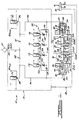
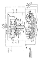
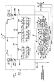
- Figures 1 through 4 illustrate various preferred embodiments of self-regulating, proportional pressure control valves according to the present invention.
- the present invention is particularly adaptable and advantageous in pneumatic control valves, and is shown for purposes of illustration in a spool-type pneumatic control valve, one skilled in the art will readily recognize that the principles of the present invention are equally applicable to poppet valves, other known types of pneumatic valves, and even to various types of hydraulic control valves.
- an exemplary self-regulating, four-way proportional pressure control valve assembly 10 generally includes a pilot operator portion 12 and a working fluid outlet portion 14.
- the control valve assembly 10 is adapted for controlling the operation of a working fluid-powered device, such as the cylinder 16, including a reciprocable piston 18 that divides the cylinder 16 into two working fluid chambers 20 and 22.
- a working fluid-powered device such as the cylinder 16
- reciprocable motion of the piston 18 is effected to drive an associated system or device, and by controlling the pressure levels in the fluid chambers 20 and 22, it is possible to control the output force levels of the cylinder, regardless of piston velocity.
- rotary motors, turbines, etc. can be controlled by the proportional pressure control valve assembly 10.
- the output portion 14 of the control valve assembly 10 generally includes a control valve body, schematically illustrated and indicated by reference numeral 26, with a bore 28 extending through the body 26, which is closed off at opposite ends by end closures or caps 30 and 32.
- the end caps 30 and 32 have respective bores 34 and 36 extending longitudinally through a portion thereof, for slidably receiving respective control pistons 38 and 40.
- a spool 42 is slidably housed within a sleeve 27 in the bore 28 of the body 26, and is interconnected with control pistons 38 and 40 by way of respective push rods or pins 44 and 46.
- the spool 42 includes a number of lands 48, 50, and 52, which are spaced apart to form recesses 54 and 56 therebetween on the spool 42.
- the ends 39 and 41 of the control pistons 38 and 40, respectively are larger than the ends 49 and 53 of the lands 49 and 52, respectively, on the spool 42.
- a typical ratio of the area of the end 41 of the control piston 40 to the end 49 of the land 48, and similarly the area ratio of the end 39 of the control piston 38 to the end 53 of the land 52 , is approximately two-to-one, although other area ratios can alternatively be employed, depending upon the proportional pressure control level desired in a given application. The purpose of such end area relationship is discussed in more detail below.
- the output portion 14 of the control valve assembly 10 also includes an inlet port 60, which provides fluid communication from a pressurized working fluid source (not shown) and the interior midpoint of the sleeve bore 28 extending through the control valve body 26.
- a pair of load ports 62 and 64 which are in fluid communication with the fluid chambers 20 and 22, respectively, of the cylinder 16, also provide fluid communication with the interior of the bore 28.
- a pair of exhaust ports 66 and 68 are provided in the body 26 in order to provide fluid communication between the interior of the bore 28 and the atmosphere or other exhaust region, as is well-known to those skilled in the art.
- the pilot operator portion 12 of the control valve assembly 10 includes a pilot control fluid inlet 80, which is in fluid communication, preferably by way of a filter 81, with a source of pressurized pilot control fluid (not shown).
- the pilot inlet port 80 splits into two opposed pilot circuits, which include fixed pilot orifices 82 and 84, respectively.
- the control fluid flows through the respective fixed pilot orifices 82 and 84 and is in communication with a pair of exhaust or vent orifices 86 and 88, respectively, which can be alternately closed or opened by operation of solenoid operators 90 and 92, respectively.
- pilot fluid circuits or internal ports or passageways 94 and 96 are connected in fluid communication with the respective bores 34 and 36, in the end caps 30 and 32, respectively, and with the pilot control pressure levels downstream of the respective feed pilot orifices 82 and 84.
- a load level control apparatus 100 is in fluid communication with both of the pilot ports 94 and 96, which are isolated from one another by a pair of check valves 118 and 120 in a load level control port 101.
- a number of adjustable pilot control orifices 102, 104, 106, and 108, are connected in parallel with the load level control port 101, between the check valves 118 and 120.
- These adjustable orifices are in series fluid communication with respective normally closed exhaust orifices 122, 124, 126, and 128, which in turn can be alternatively opened or closed by respective solenoid operators 110, 112, 114, and 116.
- solenoid operators 110 through 116 which can also be optionally replaced by other known types of operators, serve to block control fluid flow through the corresponding variable pilot control orifices 102 through 108, respectively, when the respective orifices 122 through 128 are closed to exhaust.
- the illustrative and exemplary pressure control valve assembly 10, according to the present invention, is capable of several operating modes or conditions, all of which are described below.
- filtered control air enters the pilot portion 12 through the pilot inlet 80, after which its flow divides and is communicated through the small, fixed pilot orifices 82 and 84.
- pilot fluid flow is blocked, and the pilot control fluid pressures in the pilot ports 94 and 96 both stabilize generally at pilot inlet fluid pressure level. This condition assumes, of course, that the solenoids 110 through 116 in the load level control apparatus are also de-energized so as to hold the respective orifices 122 through 128 in their closed conditions.
- Such stabilized pilot inlet pressures in the pilot ports 94 and 96 are in communication with the respective bores 34 and 36, with their respective control pistons 38 and 40. Since these control pressures are equal, but act in opposite directions on the respective control pistons 38 and 40, the spool 42 in the output portion 14 remains at its center-off position, with the working fluid flow from the inlet port 60 being prevented from passing to other portions of the bore 28 in the body 26, such as the load ports 62 and 64.
- the control valve assembly 10 of the present invention maintains the center-off position of the spool 42 with zero load port pressures, and accomplishes this condition with substantially no pilot fluid flow or electrical input, with the possible exception of a very small, negligible system leakage or loss.
- the control valve assembly 10 in Figure 1 is also capable, however, of an "unregulated" mode of operation in the sense that the pressure at the load outlet ports is not controlled.
- the spool 42 is operated either at its extreme right and left travel positions, or at its zero output center position.
- the load output is essentially the same as the supply pressure, and is thus unregulated.
- the solenoid operators 110 through 116 are de-energized, thus maintaining the exhaust orifices 122 through 128, respectively, in their closed condition.
- the solenoid 90 in the pilot operator portion 12 is energized in order to open the orifice 86 to atmosphere, thus allowing control fluid flow through the fixed pilot orifice 82 to exhaust to atmosphere.
- the size of the open orifice 86 is several times larger than the size of the opening through the fixed orifice 82, thus causing the pressure in the pilot port 94 to drop to atmospheric, or near atmospheric, level.
- control fluid pressure in the pilot port 96 is at or near inlet control fluid pressure, and the pressure in the pilot port 94 is substantially equal to atmospheric pressure, a large force unbalance is created on the control pistons 38 and 40. This results in a substantially full movement of the spool 42 to the right, as viewed in Figure 1, until such movement is stopped by contact between the end 39 of the control piston 38 and the end wall of the bore 34 in the end cap 30, or due to engagement of the spool 42 with a spool stop (not shown). In this spool position, the inlet port 60 is in fluid communication, by way of the recess 54 with the load port 64, thus pressurizing the right-hand fluid chamber 22 of the cylinder 16.
- the load port 62 is in fluid communication, by way of the recess 56, with the exhaust port 66, thus exhausting the left-hand fluid chamber 20 of the cylinder 16.
- a pressure imbalance between the fluid chambers 22 and 20 causes the piston 18 to move leftward within the cylinder 16, and a mechanical connection between the piston 18 causes operation of an associated device or system.
- the output portion 14 of the control valve assembly 10 also preferably includes a pair of internal feedback ports or passageways 72 and 74, which provide for a "self-regulated" mode of operation.
- This self-regulated mode of operation comes into play only with lower load pressures, resulting from lower pilot pressures such that the spool 42 is operated at positions between the extreme travel ends.
- the feedback passageways 72 and 74 provide fluid communication between the recess 54 and the end 53 of the spool 42, and between the recess 56 and the end 49 of the spool 42, respectively.
- the spool 42 is moved to the left, as viewed in Figure 1, and the internal feedback passageway 74 provides fluid communication from the load port 62, by way of the recess 56, to the spool end 49 in order to provide a rightwardly-directed load pressure feedback to the end spool 49. This opposes the leftward movement of the spool 42.
- the spool tends to stabilize at a force-balanced leftward position such that the load pressure at load port 62 is proportional to the pilot pressure and is in the same ratio to the pilot pressure at the piston end 39 as the ratio of the area of the piston end 39 to the area of the spool end 49 (two-to-one, for example).
- the feedback passageway 72 is vented to atmosphere because such leftward movement of the spool 42 causes communication between the feedback passageway 72 and the recess 54 with the exhaust port 68, as well as causing communication of the load port 64 with the exhaust port 68.
- the feedback passageway 74 is vented to atmosphere because the rightward movement of the spool 42 causes communication between the feedback passageway 74 and the recess 56 with the exhaust port 66, as well as causing communication of the load port 62 with the exhaust port 66.
- control valve assembly 10 is remotely operable, and programmable, either in a pre-adjustable manner as in the following description, or in a continuously variable manner, which will be described and explained still later in this detailed description.
- the control valve assembly 10 In the "regulated" mode, the control valve assembly 10 is provided with a pressure selectivity in which two or more pressure levels can be preset.
- the variable load control orifices 102, 104, 106, and 108 which are ported to their respective normally-closed, solenoid-operated exhaust orifices 122, 124, 126, and 128, are each independently adjustable. It should be noted that although four adjustable pilot control orifices 102 through 108 are shown for purposes of illustration in Figure 1, the system can alternately have any number of such adjustable pilot control orifices.
- one or more of these preset adjustable pilot control orifices 102 through 108 can be remotely called into play by operation of the corresponding associated solenoid-operated exhaust orifices 122 through 128 to cause any of a number of preset load pressure levels to be available at either the load port 62 or the load port 64.
- this pressure selectivity feature can perhaps best be described by way of the following example. Assume that leftward movement of the piston 18 in the cylinder 16 is desired, that the pressure in the chamber 22 of the cylinder 18 is desired to be limited to a maximum of 20 p.s.i.g., and that the valve inlet pressure at the inlet port 60 is 100 p.s.i.g. Initially the spool 42 is in its center-off or neutral position so long as all the solenoids are not energized, thus resulting in no load output at load ports 64 and 66.
- the solenoid 90 When the solenoid 90 is energized, the orifice 86 is opened, and the pilot pressure at the pilot port 94 and the pressure at the piston end 39 of the piston 38 both drop to atmospheric level. Because the piston end 41 of the piston 40 is still subjected to pilot pressure, the large differential force on the pistons 38 and 40 causes the spool 42 to move to the right, as viewed in Figure 1. If the adjustable orifice 102 has been preset to a 10 p.s.i.g. pressure drop, energizing the solenoid 110 will open the orifice 122 and cause the pilot pressure in the pilot port 96 to drop to 10 p.s.i.g. due to pilot air being exposed to atmosphere by way of the adjustable orifice 102 and the open orifice 122.
- pilot air in the pilot port 96 passes through the check valve 118, but is prevented from entering the pilot port 94 by the check valve 120. It should also be noted that if the 20 p.s.i.g. load output is desired to be transferred to the opposite cylinder chamber 20 in order to move the piston 18 rightwardly, all that needs to be done is to energize the solenoid 92 as the solenoid 90 is de-energized, thus reversing the movement of the spool 42, while leaving the solenoid 110 in its energized state.
- the spool will always stabilize at a force-balanced position that provides the same ratio of load pressure to the pilot pressure as is the ratio of the control piston end area to the spool end area. Therefore, if this end area ratio is two-to-one, as in the example given above, the spool will stabilize and come to rest at a position that results in a self-regulated load pressure of 20 p.s.i.g. for a preset pilot pressure of 10 p.s.i.g.
- the "regulated" mode of operation discussed above provides for a number of self-regulated, selective load pressures, with the capability of at least four independently adjustable preset pilot pressures being shown in the example illustrated in Figure 1, each corresponding to one of the four adjustable orifices 102 through 108.
- Still another selectable load pressure is the load pressure that results if all of the solenoids 110 through 116 are de-energized (and the associated respective orifices 122 through 128 are closed), and only the solenoid 90 or 92 is energized, in which case the load pressure at either the load port 64 or the load port 62, respectively, is essentially equal to the inlet pressure, and is essentially unregulated, as is discussed above.
- any of several preselected load pressures can be maintained merely by energizing one of the solenoids 110 through 116, each of which is associated with one of the preset variable pilot orifices 102 through 108, each of which in turn can be pre-adjusted to different pressure drops, thus resulting in a variety of different pilot control pressures.
- any two or more of the solenoids 110 through 116 can be energized simultaneously, in order to cause simultaneous flow through the respective corresponding variable pilot control orifices 102 through 108, thus providing even lower selectable pilot control pressures and resultant proportional load pressures.
- the solenoids 110 through 116 can be energized singly or in various combinations, it is possible to achieve a pilot control pressure (and resultant proportional load pressure) that is lower than that resulting from operation of the lowest set variable pilot control orifice 102, 104, 106, or 108. This is because operation of any one of the variable orifices in conjunction with operation of the lowest set variable orifice results in a reduction of pilot pressure upstream of each of the variable orifices to which flow is being allowed.
- variable pilot control orifice 102 For example, if the variable pilot control orifice 102 is set for a load pressure of 20 p.s.i.g. when the solenoid 110 is singly energized, and if the variable pilot control orifice 104 is set at 20 p.s.i.g. for a load pressure of 40 p.s.i.g. when the solenoid 112 is singly energized, energization of both the solenoids 110 and 112 will result in a reduction in pilot pressure, which in turn corresponds to a load pressure less than the 20 p.s.i.g. level for which variable pilot control orifice 102 is set.
- variable pilot control orifices 102 through 108 is preferably done with each of the variable pilot control orifices singly in operation, independently of the other variable load control orifices, and such pre-adjustment or presetting is preferably done to achieve a desired load output pressure attainable when the orifice being adjusted is brought into play by energizing its associated solenoid.
- the spool 42 and the sleeve 27 are preferably of the conventional, close-fitting, hardened and ground component configuration.
- O-ring type seals for outside-diameter sealing are used on the sleeve 27 to seal in the body 26.
- the end caps 30 and 32 each preferably house close-fitting, axially-mounted control pistons, which bear against the spool ends by way of the push rods or push pins 44 and 46, which act through low-friction seals.
- variable pilot control orifices 102 through 108 can be arbitrarily and independently pre-adjusted and locked to produce the desired load pressure level. It should be noted, however, that such pre-adjusted pilot pressure setting can only be made and later called into operation by energizing the corresponding solenoids 110 through 116, either singly or in any of a number of combinations.
- the control valve assembly 10 shown for purposes of illustration in Figure 1 is pre-programmable and remotely and selectively operable to effect any of a finite number of pre-selected pilot pressure and load pressure levels. In some systems, however, it is necessary, or at least desirable or advantageous, to provide for an infinite number of selectively variable load pressure levels.
- a control valve assembly 110 adapted to provide this capability is described below and schematically illustrated in Figure 2, wherein many of the components are substantially the same as those of Figure 1, and are thus indicated by the same reference numerals.
- pilot level control apparatus 100 as well as the solenoids 90 and 92 and their corresponding exhaust or vent orifices 86 and 88, are replaced by an infinitely variable pilot level control apparatus 200.
- the preferred pilot level control apparatus 200 includes a spring-centered, bi-directional, opposed-coil torque motor 201, which operates to move its armature assembly 202 between opposed pilot control nozzle assemblies 203 and 204.
- the electro-magnetic torque motor 201 includes opposed pole pieces or cores 205 and 206, generally surrounded by respective electrical coils 207 and 208, which are independently energizable at infinitely varying input current levels, up to the capacity of the torque motor 201.
- a yoke 210 transcends the opposite ends of the pole pieces 205 and 206 and serves as a conduit or path for magnetic flux.
- An armature member 211 is preferably resiliently supported for spring-centered pivotal movement between the pilot control nozzle assemblies 203 and 204 by a resilient spring support member 212, although other spring-centered pivotal support devices can alternately be employed so long as they allow sufficiently free pivotal movement of the armature member 211, as will be described in further detail below.
- Attached to opposite sides of the longitudinally-extending armature member 211 are longitudinally-extending resilient nozzle closure members 213 and 214.
- the closure members 213 and 214 function similar to cantilevered leaf springs with their free ends laterally spaced on opposite sides of the armature member 211, such that they are resiliently biased in opposite directions toward the respective pilot control nozzle assemblies 203 and 204.
- pilot control nozzle assemblies 203 and 204 include respective adjustable nozzle members, only one of which (nozzle member 215 in assembly 203) is shown in Figure 2 as a typical construction for both assemblies 203 and 204.
- a nozzle inlet port 217 extends into the typical pilot control nozzle assembly 203 and is connected with the pilot orifice 84, with the pilot port 96 also being in fluid communication with the control piston 40 by way of the bore 36.
- the pilot control nozzle assembly 204 is connected with the pilot orifice 82, with the pilot port 94 also being connected in fluid communication with the control piston 38 by way of the bore 34.
- the nozzle inlet port 217 also communicates with an opening 219 that terminates at the nozzle end 221 (nozzle end 222 for nozzle assembly 204).
- the nozzle ends 221 and 222 are engageable by the respective closure members 213 and 214, which are resiliently biased in opposite directions, away from the armature member 211 and toward the respective nozzle ends 221 and 222.
- the pilot level control apparatus 200 functions in the following manner in order to provide infinitely variable pilot control pressures, with infinitely variable and proportional load pressure levels, while still providing the capability of substantially zero pilot flow at zero input signal when the control valve assembly 110 is in its center-off or neutral condition.
- the armature member 211 is spring-centered between the pole pieces 205 and 206 by virtue of the center-biased spring support member 212.
- the nozzle closure members 213 and 214 are substantially equally biased away from the armature member 211 toward equal-force sealing engagement with their respective nozzle ends 221 and 222 to prevent venting of either of the pilot ports 94 or 96.
- pilot control pressures in pilot ports 94 and 96 are substantially balanced, and are generally equal to the pilot inlet pressure at the pilot inlet 80. Consequently, the spool 42 in the output portion 14 is balanced at its center-off position, with substantially no pilot control fluid flow or electrical input signal and consequently with no flow from the load ports 62 or 64.
- signal current is allied to one or the other (or both) of the electrical coils 207 or 208, thus causing the armature 211 to move closer to the pole piece (205 or 206) surrounded by its respective energized coil.
- Such armature movement increases the sealing force exerted by the closure member (213 or 214) against its respective nozzle end (221 or 222) at the energized (or greater energized) side of the torque motor 201.
- the armature member 211 pulls the other closure member (213 or 214) at the non-energized or lesser energized side of the torque motor 201, in a direction away from its respective pilot control nozzle end (221 or 222), thus allowing at least partial venting at the non-energized (or lesser energized) side.
- pilot pressure in the pilot port (94 or 96) on the energized (or greater energized) side of the system increases or remains at pilot inlet level with increasing input signal current
- pilot pressure in the opposite pilot port (94 or 96) at the non-energized (or lesser energized) side of the system decreases with increasing movement of its associated closure member (213 or 214) in a direction away from its respective pilot control nozzle end (221 or 222).
- the resultant pressure imbalance between the pilot ports 94 and 96 causes corresponding movement of the control pistons 38 and 40 and thus the spool 42, with internal self-regulating feedback as described above in connection with Figure 1, holding the output load pressure to a level that is twice the differential pilot pressure level (in the above example).
- the torque motor 201 is capable of infinitely variable bi-directional movement of the armature 211 between the pilot control nozzle ends 221 and 222 in response to infinitely variable differential input signal currents to respective electric coils 207 and 208
- the pilot level control apparatus 200 is capable of infinitely variable bi-directional movement of the spool 42 and corresponding self-regulated, infinitely variable, load pressures in order to cause reciprocating operation of the cylinder 16, with resulting control of the output force levels therein.
- the pilot level control apparatus 200 is thus capable of extremely fine and close control of force levels at the cylinder 16 due to the fact that very small differences in the input signal currents to the coils 207 and 208 result in very small movements of the armature 211 and thus very small differences in pilot pressures at the respective nozzle ends 221 and 222. Furthermore, since the armature movement and pilot pressures are directly proportional to input signal current, and the load pressures are directly proportional to the pilot pressures, the load pressures are directly proportional to input signal current and are correspondingly infinitely and finely controllable.
- FIG. 1 schematically illustrates a simplified version of the present invention wherein such selective variations in load pressures are not needed, but in which self-regulating proportional control of one pressure level is available.
- the pilot level control apparatuses 100 and 200 of Figures 1 and 2 are omitted, and adjustable orifices 382 and 384 are added to the system.
- the adjustable orifices 382 and 384 are in fluid communication with the respective orifices 82 and 84 and their respective normally-closed exhaust orifices 86 and 88.
- the exhaust orifices 86 and 88 are controlled by the solenoids 90 and 92, respectively.
- the orifices 382 and 384 can be adjustably preset and locked to orifice sizes that result in a preselected differential pilot pressure drop resulting in a desired, preselected load pressure level at load port 62 or at load port 64.
- the spool 42 moves to a position resulting in the preselected load pressure level. If a different load pressure level or output direction is desired, the respective orifices 382 and 384 must be unlocked, set for the new desired load pressure, and again locked at their new settings.
- pilot pressures in pilot ports 94 and 96 are each set, by way of adjustment of orifices 382 and 384, respectively, to generate a differential control pressure across the control pistons 38 and 40, respectively.
- the magnitude of each adjusted pilot pressure is limited, by design requirements, to a maximum of 50 percent of the valve inlet supply pressure. The reason for this limitation is to allow the spool 42 to remain at its travel stop with a minimum differential pilot signal across the control pistons equal to 50 percent of the valve inlet supply pressure when operating in the single solenoid control mode.
- solenoid 90 or solenoid 92 causes the pilot pressure at the pilot ports 94 or 96, respectively, to drop to a maximum level of 50 percent of valve inlet supply pressure (by way of prior adjustment).
- the pilot pressure at the opposite pilot port is, of course, at 100 percent of the valve inlet supply level since its exhaust orifice is blocked (due to de-energized solenoid).
- the spool 42 is thus displaced to its travel stop, at which time air from the inlet port 60 to one of the load ports 62 or 64 (depending upon pilot direction) will begin to flow.
- the maximum level that this load pressure can attain which is the same as the feedback signal pressure, is not sufficient to move the spool 42 off its stop and back toward center.
- the spool 42 thus remains at its travel stop, and the valve output load pressure is essentially unregulated and is at or near valve inlet supply level.
- FIG 4 schematically illustrates still another variation on the present invention that is similar to that of Figure 3, but which incorporates the capability of input signal pulse width modulation in order to variably control load output.
- a control valve assembly 410 is substantially identical in terms of its configuration or hardware to the control valve assembly 310, but can be operated somewhat differently.
- the pre-adjustable orifices 382 and 384 are generally not needed for this type of pilot control and would be retracted to reduce the restriction in pilot flow to exhaust.
- the current input signals to each of the solenoids 90 and 92 can be modulated, either singly or simultaneously, by modulating their on-off pulse widths to correspondingly modulate pilot pressure levels.
- the difference between the two average pilot pressures is the control piston differential pressure signal, which displaces the spool 42 in the same manner as described above in connection with other exemplary embodiments.
- the reference numeral 415 indicates a plot of input signal versus time for solenoids 90 and 92, wherein the input signal pulse width is modulated the same for both solenoids 90 and 92.
- This operational mode results in equal pilot pressure averaging acting in opposite directions on both control pistons 38 and 40 of the output portion 14, for equal coincident time periods.
- the spool 42 will remain at its center-off position.
- the respective electrical input signals are pulse-width modulated in a manner such that the solenoids 90 and 92 are energized for different durations, an unbalanced signal differential results, such as that illustrated by reference numerals 416 and 417.
- the spool 42 will be caused to drift toward one side or the other, as a result of the correspondingly unbalanced pilot pressures exerted on the control pistons 38 and 40. Therefore, by selectively modulating the pulse widths of the electric input signals to solenoids 90 and 92, and consequently modulating the respective pilot pressures exerted on the respective control pistons 38 and 40, the load outputs at the respective load ports 62 and 64 can be closely controlled.
- such electrical input signals can be programmed, using microprocessors or other known electrical or electronic signal processing devices, to cause a programmed, desired load output sequence in order to attain a desired operational force control sequence of the cylinder 16.
- the operation of the cylinder 16 can be programmed in the sense that operational external feedback signals from the system in which the cylinder 16 is used can be used by appropriate electrical signal processors to adjust the electrical signal input sequences for the solenoids 90 and 92 in response to changing system conditions.
- electrical signal processing devices or apparatuses are well-known to those skilled in the art and thus are not described in detail herein.
- the various illustrative and exemplary alternate embodiments of the present invention offer a wide variety of capabilities for controlling control valves by way of external signal conditioning for a wide variety of applications.
- Such capabilities include simplified control where maximum load output variations or adjustability is neither desired nor required, as well as providing for applications where infinite variations or adjustability of the load output is needed.
- Such capabilities are provided in a control valve apparatus that is relatively simple to operate and relatively inexpensive while still offering the high degree of control precision required in many modern applications.
Landscapes
- Engineering & Computer Science (AREA)
- Physics & Mathematics (AREA)
- Fluid Mechanics (AREA)
- Mechanical Engineering (AREA)
- General Engineering & Computer Science (AREA)
- Servomotors (AREA)
- Fluid-Driven Valves (AREA)
- Fluid-Pressure Circuits (AREA)
- Multiple-Way Valves (AREA)
- Control Of Fluid Pressure (AREA)
Claims (15)
- Dispositif de soupape de commande de fluide possédant un orifice d'admission (60) de fluide de travail pouvant être relié à une source de fluide de travail pressurisé, une paire d'orifices de sortie (62, 64) de charge de fluide de travail, un élément de soupape mobile (42), un opérateur pilote (38, 40) pour appliquer sélectivement une pression de fluide de commande à l'élément de soupape mobile (42) afin de faire communiquer un orifice de sortie sélectionné parmi les orifices de sortie de charge (62, 64) avec l'orifice d'admission (60) de fluide de travail pour produire des pressions d'orifice de sortie de charge en fonction de la position de l'élément de soupape mobile (42), et des moyens d'auto-régulation (72, 74) pour maintenir la pression d'orifice de sortie de charge, lesdits moyens d'auto-régulation comprenant des moyens de rétroaction (72, 74) pour utiliser la pression d'orifice de sortie de charge provenant dudit orifice de sortie de charge sélectionné (62, 64) pour pousser ledit élément de soupape mobile (42) dans une direction s'opposant au déplacement de l'élément mobile dans une direction qui fait communiquer l'orifice d'admission (60) de fluide de travail avec ledit orifice de sortie de charge sélectionné (62, 64), caractérisé en ce que le dispositif de soupape de commande de fluide est un dispositif pneumatique apte à fonctionner avec un fluide de travail pneumatique, l'opérateur pilote comprend une paire de pistons de commande (38, 40) reliés à des côtés opposés de l'élément de soupape mobile (42), l'opérateur pilote étant sélectivement actionnable pour appliquer une pression de fluide de commande à un piston choisi desdits pistons de commande (38, 40) et pour évacuer une pression de fluide de commande de l'autre desdits pistons de commande afin de provoquer un mouvement sélectif de l'élément de soupape mobile (42) dans l'une ou l'autre de directions opposées, lesdits moyens d'auto-régulation (72, 74) étant aptes à maintenir la pression de l'orifice de sortie de charge proportionnelle à la pression du fluide de commande et comprend des parties (48, 52) sur des côtés opposés de l'élément de soupape mobile (42), lesdits moyens de rétroaction (72, 74) étant, en utilisation, en communication fluidique avec lesdites parties de l'élément de soupape (48, 52) pour appliquer une pression de charge à l'une desdites parties d'élément de soupape (48, 52) afin d'assurer ladite poussée dudit élément de soupape mobile (42), la surface de chacun desdits pistons de commande (38, 40) étant supérieure à la surface de chacune desdites parties d'élément de soupape (48, 52), la pression de sortie de charge audit orifice de sortie de charge sélectionné (62, 64) étant, en utilisation, proportionnelle à la pression du fluide de commande appliquée audit premier desdits pistons de commande (38, 40) dans le même rapport que le rapport de la surface dudit premier desdits pistons de commande (38, 40) à la surface de ladite première desdites parties d'élément de soupape (48, 52), l'opérateur pilote comprenant en outre des moyens (90, 92, 203, 204) pour appliquer sélectivement des pressions de fluide de commande égales auxdits deux pistons de commande (38, 40) simultanément afin de maintenir l'élément de soupape mobile (42) dans une position excentrée avec pratiquement aucun écoulement de fluide de travail et pratiquement aucun écoulement de fluide de commande, lesdits moyens d'auto-régulation (72, 74) tendant également à maintenir l'élément de soupape mobile (42) dans ladite position excentrée dans le cas d'un déplacement indésirable depuis ladite position excentrée.
- Dispositif selon la revendication 1, dans lequel la surface de chacun desdits pistons de commande (38, 40) est approximativement le double de la surface de chacune des parties d'élément de soupape (48, 52).
- Dispositif selon la revendication 1 ou la revendication 2, dans lequel des moyens de réglage (90, 92, 102, 104, 106, 108, 201, 382, 384) sont prévus pour régler sélectivement la pression du fluide de commande appliquée à chacun desdits pistons de commande (38, 40) à un niveau de pression prédéterminé.
- Dispositif selon la revendication 3, dans lequel lesdits moyens de réglage (102, 104, 106, 108, 382, 384) sont aptes à régler sélectivement la pression du fluide de commande appliquée à chacun desdits pistons de commande (38, 40) à l'un quelconque d'une pluralité de niveaux de pression prédéterminés.
- Dispositif selon la revendication 4, dans lequel lesdits moyens de réglage (90, 92, 201) sont aptes à régler sélectivement la pression du fluide de commande appliquée à chacun desdits pistons de commande (38, 40) à l'un quelconque d'un nombre infini de niveaux de pression.
- Dispositif selon l'une quelconque des revendications précédentes, dans lequel l'opérateur pilote comprend des moyens de modulation pour moduler sélectivement et séparément l'application de la pression de fluide de commande à, et pour évacuer la pression du fluide de commande de chacun desdits pistons de commande (38, 40) afin de déplacer sélectivement l'élément de soupape mobile (42) dans l'une quelconque d'une pluralité de positions afin de commander sélectivement le niveau de pression du fluide de travail communiqué audit orifice de sortie de charge sélectionné (62, 64).
- Dispositif selon la revendication 6, dans lequel lesdits moyens de modulation comprennent un orifice (102, 104, 106, 108, 382, 384) en communication fluidique avec chacun desdits pistons de commande (38, 40), et des électro-aimants (90, 92) excitables sélectivement pour faire communiquer chacun desdits pistons de commande avec l'atmosphère par l'intermédiaire dudit orifice afin d'en évacuer sélectivement la pression de fluide de commande, et des moyens de commande pour moduler séparément et sélectivement indépendamment la durée d'excitation et de désexcitation de chacun desdits électro-aimants.
- Dispositif selon la revendication 7, dans lequel lesdits orifices (102, 104, 106, 108, 382, 384) sont préréglables à une dimension d'orifice prédéterminée correspondant à une pression de sortie de charge prédéterminée.
- Dispositif selon la revendication 8, dans lequel une pluralité desdits orifices (102, 104, 106, 108, 382, 384) sont prévus, chacun étant préréglable à une dimension d'orifice prédéterminée corespondant à une pression de sortie de charge prédéterminée, lesdits moyens de commande étant aptes à faire communiquer sélectivement chacun desdits pistons de commande (38, 40) avec l'atmosphère par l'intermédiaire desdits orifices, à la fois individuellement et conjointement avec un autre desdits orifices.
- Dispositif selon la revendication 9, dans lequel lesdits moyens de commande comprennent des électro-aimants de commande pilotes (90, 92, 110, 112, 114, 116) associés à chacun desdits orifices (102, 104, 106, 108, 382, 384), lesdits électro-aimants de commande pilotes pouvant être excités chacun sélectivement et à distance pour provoquer ladite communication entre chacun desdits pistons de commande (38, 40) et l'atmosphère par l'intermédiaire desdits orifices, à la fois individuellement et conjointement avec un autre desdits orifices.
- Dispositif selon l'une quelconque des revendications précédentes, dans lequel des électro-aimants (90, 92) dans ledit opérateur pilote et associés à chacun desdits pistons de commande (38, 40) peuvent être désexcités sélectivement pour appliquer une pression de fluide de commande à chacun desdits pistons de commande, lesdits électro-aimants étant désexcitables pour appliquer une pression de fluide de commande auxdits pistons de commande simultanément afin de maintenir l'élément de soupape mobile (42) dans ladite position excentrée sensiblement sans application de courant électrique auxdits électro-aimants.
- Dispositif selon la revendication 1, dans lequel l'opérateur pilote comprend des moyens de commande pilotes (200) dans l'opérateur pilote pour modifier sélectivement et infiniment la pression de sortie de charge en chacun des orifices de sortie de charge (62, 64), lesdits moyens de commande pilotes comprenant un moteur-couple électrique (201) possédant un induit mobile bidirectionnel (211), une paire de bobines électriques excitables sélectivement (207, 208) pour déplacer ledit induit dans des directions opposées choisies, lesdits moyens de commande pilotes comprenant en outre une paire de buses de commande pilotes ouvertes opposées (221, 222) sur des côtés opposés dudit induit, chacune desdites buses de commande se trouvant en communication fluidique avec l'un desdits pistons de commande (38, 40) et avec l'atmosphère, et des éléments de fermeture de buse (213, 214) portés par ledit induit mobile pour engager lesdites buses de commande pilotes (221, 222) avec une force d'engagement infiniment variable en réponse à un déplacement dudit induit mobile afin de modifier infiniment la dimension de l'ouverture de buse et la perte de charge entre lesdits pistons de commande (38, 40) et l'atmosphère afin de modifier infiniment de façon correspondante la pression de fluide de commande appliquée auxdits pistons de commande et modifier de façon correspondante la pression de sortie de charge proportionnelle audit orifice de sortie de charge choisi (62, 64), lesdits éléments de fermeture (213, 214) étant solli- cités élastiquement pour s'écarter dudit induit (211) dans des directions opposées afin d'engager lesdites buses de commande pilotes (221, 222) avec une force d'engagement égale lorsque lesdites deux bobines électriques (207, 208) sont désexcitées afin d'équilibrer la pression de fluide de commande appliquée aux pistons de commande et maintenir l'élément de soupape mobile (42) dans ladite position excentrée sensiblement sans écoulement de sortie de charge, sensiblement sans écoulement de fluide de commande, et sensiblement sans aucun signal électrique appliqué auxdites bobines électriques (207, 208).
- Dispositif selon la revendication 1, dans lequel l'opérateur pilote comprend des électro-aimants (90, 92) associés à chacun desdits pistons de commande (38, 40) excitables sélectivement pour évacuer la pression du fluide de commande de chacun desdits pistons de commande et désexcitables sélectivement pour appliquer une pression de fluide de commande à chacun desdits pistons de commande, lesdits électro-aimants étant également désexcitables pour appliquer une pression de fluide de commande auxdits deux pistons de commande simultanément afin de maintenir l'élément de soupape mobile (42) dans ladite position excentrée sensiblement sans aucun signal électrique appliqué auxdits électro-aimants, ledit opérateur pilote comprenant en outre un orifice préréglable (382, 384) en communication fluidique avec chacun desdits pistons de commande, l'un desdits électro-aimants étant excitable pour faire communiquer chacun desdits pistons de commande avec l'atmosphère par l'intermédiaire d'un desdits orifices préréglables, ledit préréglage desdits orifices provoquant une chute de pression préréglable à travers ceux-ci afin de prérégler la pression de fluide de commande et la pression de sortie de charge proportionnelle correspondante audit orifice de sortie de charge sélectionné.
- Dispositif selon la revendication 13, dans lequel des moyens de modulation électrique sont associés auxdits électro-aimants (90, 92) pour moduler sélectivement et séparément la durée d'excitation et de désexcitation de chacun desdits électro-aimants afin de moduler sélectivement et séparément l'application de la pression de fluide de commande à et l'échappement de la pression de fluide de commande de chacun desdits pistons de commande (38, 40) afin de déplacer sélectivement l'élément de soupape mobile (42) dans l'une quelconque d'une pluralité de positions et ainsi sélectivement commander la pression de sortie de charge audit orifice de sortie de charge choisi (62, 64).
- Dispositif selon l'une quelconque des revendications précédentes, dans lequel la surface de chacune desdites parties d'élément de soupape (48, 52) est sensiblement égale à la surface de section latérale dudit élément de soupape mobile (42).
Applications Claiming Priority (2)
| Application Number | Priority Date | Filing Date | Title |
|---|---|---|---|
| US290745 | 1988-12-27 | ||
| US07/290,745 US4883091A (en) | 1988-12-27 | 1988-12-27 | Multi-port self-regulating proportional pressure control valve |
Publications (2)
| Publication Number | Publication Date |
|---|---|
| EP0376440A1 EP0376440A1 (fr) | 1990-07-04 |
| EP0376440B1 true EP0376440B1 (fr) | 1994-05-18 |
Family
ID=23117371
Family Applications (1)
| Application Number | Title | Priority Date | Filing Date |
|---|---|---|---|
| EP19890309763 Expired - Lifetime EP0376440B1 (fr) | 1988-12-27 | 1989-09-26 | Distributeur proportionnel à plusieurs voies à réglage automatique de la pression |
Country Status (8)
| Country | Link |
|---|---|
| US (1) | US4883091A (fr) |
| EP (1) | EP0376440B1 (fr) |
| JP (1) | JP2575908B2 (fr) |
| CN (1) | CN1019040B (fr) |
| CA (1) | CA1329109C (fr) |
| DE (1) | DE68915419T2 (fr) |
| ES (1) | ES2056223T3 (fr) |
| RU (1) | RU2074990C1 (fr) |
Families Citing this family (26)
| Publication number | Priority date | Publication date | Assignee | Title |
|---|---|---|---|---|
| CN1044634C (zh) * | 1996-11-13 | 1999-08-11 | 中国人民解放军第二炮兵工程学院 | 大型起竖设备液压系统 |
| US5918631A (en) * | 1998-04-14 | 1999-07-06 | Ross Operating Valve Company | Ball-poppet pneumatic control valve |
| US6198369B1 (en) | 1998-12-04 | 2001-03-06 | Tlx Technologies | Proportional actuator for proportional control devices |
| US6392516B1 (en) | 1998-12-04 | 2002-05-21 | Tlx Technologies | Latching solenoid with improved pull force |
| US6431207B1 (en) | 2000-03-16 | 2002-08-13 | Ross Operating Valve Company | High-pressure ball-poppet control valve |
| US7213612B2 (en) * | 2000-03-16 | 2007-05-08 | Ross Operating Valve Company | High pressure ball-poppet control valve with flow control |
| US6431209B1 (en) | 2000-03-16 | 2002-08-13 | Ross Operating Valve Company | Multi-pressure ball-poppet control valve |
| US6805328B2 (en) | 2002-06-04 | 2004-10-19 | Maxon Corporation | Shut-off valve apparatus |
| US6789563B2 (en) | 2002-06-04 | 2004-09-14 | Maxon Corporation | Pneumatic exhaust controller |
| DE10348582A1 (de) * | 2003-10-20 | 2005-05-19 | Marco Systemanalyse Und Entwicklung Gmbh | Ventil |
| DE102004048689B3 (de) * | 2004-10-06 | 2005-10-20 | Siemens Ag | Zweistufiges Servoventil |
| CN100572825C (zh) * | 2004-12-02 | 2009-12-23 | 雷神萨科斯公司 | 具有固有反馈系统的压力调节阀 |
| US8701697B2 (en) | 2010-06-07 | 2014-04-22 | Techmaster Inc. | Pneumatic system |
| US8910657B2 (en) * | 2007-09-06 | 2014-12-16 | Cnh Industrial America Llc | Electrically controlled pilot operated pressure regulator valve apparatus and method of operation of the same |
| RU2352827C1 (ru) * | 2007-10-15 | 2009-04-20 | Открытое акционерное общество "Омское машиностроительное конструкторское бюро" | Электрогидравлический преобразователь |
| US8333218B2 (en) * | 2010-01-27 | 2012-12-18 | Mac Valves, Inc. | Proportional pressure controller |
| JP5709583B2 (ja) * | 2011-02-28 | 2015-04-30 | ヤンマー株式会社 | 切換制御弁 |
| US9309969B2 (en) | 2013-02-22 | 2016-04-12 | Cnh Industrial America Llc | System and method for controlling a hydrostatic drive unit of a work vehicle |
| CN103388600A (zh) * | 2013-08-02 | 2013-11-13 | 徐州重型机械有限公司 | 高空作业工程机械及其伺服液压系统 |
| US10180191B2 (en) | 2014-06-20 | 2019-01-15 | Asco, L.P. | Zoned manifold assembly for solenoid valve control system |
| CN105221511B (zh) * | 2015-11-20 | 2017-06-06 | 广东水利电力职业技术学院 | 一种气动步进脉冲行程阀 |
| US10227998B2 (en) | 2015-12-31 | 2019-03-12 | Cnh Industrial America Llc | System for controlling the supply of hydraulic fluid to a work vehicle implement |
| US10104826B2 (en) | 2016-01-29 | 2018-10-23 | Cnh Industrial America Llc | System for controlling the supply of hydraulic fluid to a work vehicle implement |
| EP4079270B1 (fr) * | 2017-11-06 | 2025-08-13 | Tactile Systems Technology, Inc. | Systèmes de vêtement de compression |
| CN112639295B (zh) * | 2019-04-28 | 2023-10-13 | 白保忠 | 双流体负载互反馈自动控制装置、其驱动方法及足式移动机器 |
| RU2767676C1 (ru) * | 2021-05-03 | 2022-03-18 | Общество с ограниченной ответственностью ФЕСТО-РФ, ООО ФЕСТО-РФ | Пневматический привод системы управления исполнительными механизмами |
Citations (1)
| Publication number | Priority date | Publication date | Assignee | Title |
|---|---|---|---|---|
| US4041983A (en) * | 1975-07-09 | 1977-08-16 | Caterpillar Tractor Co. | Pressure controlled swing valve with safety feature |
Family Cites Families (20)
| Publication number | Priority date | Publication date | Assignee | Title |
|---|---|---|---|---|
| US2931389A (en) * | 1956-04-18 | 1960-04-05 | Moog Servocontrols Inc | Servo valve producing output differential pressure independent of flow rate |
| US3015317A (en) * | 1958-02-11 | 1962-01-02 | Hydraulic Res And Mfg Company | Pressure control servo valve |
| US2964059A (en) * | 1959-03-05 | 1960-12-13 | Moog Valve Co Inc | Pressure-flow servo valve |
| US3434390A (en) * | 1966-04-25 | 1969-03-25 | Bosch Arma Corp | Valve control apparatus |
| US3587617A (en) * | 1968-12-16 | 1971-06-28 | Allied Control Co | Fluid control apparatus |
| US3643682A (en) * | 1970-10-26 | 1972-02-22 | Sperry Rand Corp | Power transmission |
| JPS5323573B2 (fr) * | 1972-02-18 | 1978-07-15 | ||
| US3799200A (en) * | 1972-06-12 | 1974-03-26 | Gardner Denver Co | Flow and pressure regulating control for hydraulic motors |
| US3804120A (en) * | 1972-12-26 | 1974-04-16 | B Garnett | Electrically operated hydraulic control valve |
| US3859791A (en) * | 1973-07-09 | 1975-01-14 | American Standard Inc | Fluid operated hydraulically lapped control apparatus |
| JPS5097781A (fr) * | 1974-01-07 | 1975-08-04 | ||
| DE2446963C2 (de) * | 1974-10-02 | 1982-12-16 | Robert Bosch Gmbh, 7000 Stuttgart | Hydraulische Stelleinrichtung |
| DE2517205A1 (de) * | 1975-04-18 | 1976-10-28 | Danfoss As | Hydraulische stellvorrichtung |
| US4023593A (en) * | 1976-02-17 | 1977-05-17 | The Rucker Company | Valve and control therefor |
| US4126293A (en) * | 1976-07-16 | 1978-11-21 | Control Concepts, Inc. | Feathering valve assembly |
| US4211256A (en) * | 1977-12-14 | 1980-07-08 | Clark Equipment Company | Circulating flow hydraulic pilot system |
| US4538644A (en) * | 1983-06-09 | 1985-09-03 | Applied Power Inc. | Pressure regulator |
| US4579042A (en) * | 1984-04-20 | 1986-04-01 | Mac Valves, Inc. | Selective air pressure control system for welding and like apparatus |
| JPS6215602U (fr) * | 1985-07-12 | 1987-01-30 | ||
| EP0276056A3 (fr) * | 1987-01-23 | 1989-11-29 | Borg-Warner Automotive, Inc. | Agencement de vanne pour système de commande de débit de fluide |
-
1988
- 1988-12-27 US US07/290,745 patent/US4883091A/en not_active Expired - Fee Related
-
1989
- 1989-09-26 EP EP19890309763 patent/EP0376440B1/fr not_active Expired - Lifetime
- 1989-09-26 DE DE68915419T patent/DE68915419T2/de not_active Expired - Fee Related
- 1989-09-26 ES ES89309763T patent/ES2056223T3/es not_active Expired - Lifetime
- 1989-09-27 CA CA 613690 patent/CA1329109C/fr not_active Expired - Fee Related
- 1989-10-27 CN CN89108200A patent/CN1019040B/zh not_active Expired
- 1989-10-27 RU SU4742241 patent/RU2074990C1/ru active
- 1989-12-26 JP JP33992789A patent/JP2575908B2/ja not_active Expired - Lifetime
Patent Citations (1)
| Publication number | Priority date | Publication date | Assignee | Title |
|---|---|---|---|---|
| US4041983A (en) * | 1975-07-09 | 1977-08-16 | Caterpillar Tractor Co. | Pressure controlled swing valve with safety feature |
Also Published As
| Publication number | Publication date |
|---|---|
| RU2074990C1 (ru) | 1997-03-10 |
| DE68915419T2 (de) | 1994-09-01 |
| US4883091A (en) | 1989-11-28 |
| DE68915419D1 (de) | 1994-06-23 |
| CN1019040B (zh) | 1992-11-11 |
| ES2056223T3 (es) | 1994-10-01 |
| JP2575908B2 (ja) | 1997-01-29 |
| CA1329109C (fr) | 1994-05-03 |
| EP0376440A1 (fr) | 1990-07-04 |
| JPH02221704A (ja) | 1990-09-04 |
| CN1043980A (zh) | 1990-07-18 |
Similar Documents
| Publication | Publication Date | Title |
|---|---|---|
| EP0376440B1 (fr) | Distributeur proportionnel à plusieurs voies à réglage automatique de la pression | |
| US4014509A (en) | Proportional electromagnetic-type direction- and throttle-controlling valve | |
| US4766921A (en) | Method of operating a PWM solenoid valve | |
| US4437385A (en) | Electrohydraulic valve system | |
| US5366202A (en) | Displacement controlled hydraulic proportional valve | |
| CA1229541A (fr) | Regulateur de pression | |
| EP0066150B1 (fr) | Distributeur asservi à gain variable | |
| US5520217A (en) | Directional valve | |
| US5735122A (en) | Actuator with failfixed zero drift | |
| JPH0364744B2 (fr) | ||
| US5170692A (en) | Hydraulic control system | |
| US4540018A (en) | Pressure control valve | |
| WO1986004431A1 (fr) | Agencement de soupape numerique et electro-hydraulique | |
| US3790127A (en) | Hydraulic valve | |
| US4630523A (en) | Electrohydraulic regulating drive | |
| KR840001175B1 (ko) | 전기유압식 서어보 작동기 시스템 | |
| EP0046524B1 (fr) | Commande hydraulique à distance | |
| US3385309A (en) | Fluid flow control means | |
| US4682629A (en) | Electromagnetic proportional valves | |
| USRE33846E (en) | Electrohydraulic valve system | |
| GB2248910A (en) | Electrical operation of fluid-pressure devices | |
| EP0010117B1 (fr) | Perfectionnements aux systèmes soupapes de limitation de pression | |
| JPS6221830Y2 (fr) | ||
| US3389719A (en) | Electrohydraulic servovalve having minimum flow during quiescent operation | |
| US5179887A (en) | Captive cylinder linear solenoid valve positioner |
Legal Events
| Date | Code | Title | Description |
|---|---|---|---|
| PUAI | Public reference made under article 153(3) epc to a published international application that has entered the european phase |
Free format text: ORIGINAL CODE: 0009012 |
|
| AK | Designated contracting states |
Kind code of ref document: A1 Designated state(s): DE ES FR GB IT |
|
| 17P | Request for examination filed |
Effective date: 19900718 |
|
| 17Q | First examination report despatched |
Effective date: 19930302 |
|
| GRAA | (expected) grant |
Free format text: ORIGINAL CODE: 0009210 |
|
| AK | Designated contracting states |
Kind code of ref document: B1 Designated state(s): DE ES FR GB IT |
|
| REF | Corresponds to: |
Ref document number: 68915419 Country of ref document: DE Date of ref document: 19940623 |
|
| ITF | It: translation for a ep patent filed | ||
| ET | Fr: translation filed | ||
| REG | Reference to a national code |
Ref country code: ES Ref legal event code: FG2A Ref document number: 2056223 Country of ref document: ES Kind code of ref document: T3 |
|
| PLBE | No opposition filed within time limit |
Free format text: ORIGINAL CODE: 0009261 |
|
| STAA | Information on the status of an ep patent application or granted ep patent |
Free format text: STATUS: NO OPPOSITION FILED WITHIN TIME LIMIT |
|
| 26N | No opposition filed | ||
| PGFP | Annual fee paid to national office [announced via postgrant information from national office to epo] |
Ref country code: FR Payment date: 19950811 Year of fee payment: 7 |
|
| PGFP | Annual fee paid to national office [announced via postgrant information from national office to epo] |
Ref country code: GB Payment date: 19950825 Year of fee payment: 7 |
|
| PGFP | Annual fee paid to national office [announced via postgrant information from national office to epo] |
Ref country code: ES Payment date: 19950914 Year of fee payment: 7 |
|
| PGFP | Annual fee paid to national office [announced via postgrant information from national office to epo] |
Ref country code: DE Payment date: 19960820 Year of fee payment: 8 |
|
| PG25 | Lapsed in a contracting state [announced via postgrant information from national office to epo] |
Ref country code: GB Effective date: 19960926 |
|
| PG25 | Lapsed in a contracting state [announced via postgrant information from national office to epo] |
Ref country code: ES Free format text: LAPSE BECAUSE OF THE APPLICANT RENOUNCES Effective date: 19960927 |
|
| PG25 | Lapsed in a contracting state [announced via postgrant information from national office to epo] |
Ref country code: FR Effective date: 19960930 |
|
| GBPC | Gb: european patent ceased through non-payment of renewal fee |
Effective date: 19960926 |
|
| REG | Reference to a national code |
Ref country code: FR Ref legal event code: ST |
|
| REG | Reference to a national code |
Ref country code: FR Ref legal event code: ST |
|
| PG25 | Lapsed in a contracting state [announced via postgrant information from national office to epo] |
Ref country code: DE Free format text: LAPSE BECAUSE OF NON-PAYMENT OF DUE FEES Effective date: 19980603 |
|
| REG | Reference to a national code |
Ref country code: ES Ref legal event code: FD2A Effective date: 19991007 |
|
| PG25 | Lapsed in a contracting state [announced via postgrant information from national office to epo] |
Ref country code: IT Free format text: LAPSE BECAUSE OF NON-PAYMENT OF DUE FEES;WARNING: LAPSES OF ITALIAN PATENTS WITH EFFECTIVE DATE BEFORE 2007 MAY HAVE OCCURRED AT ANY TIME BEFORE 2007. THE CORRECT EFFECTIVE DATE MAY BE DIFFERENT FROM THE ONE RECORDED. Effective date: 20050926 |