EP0376454A2 - Kombination einer Transportvorrichtung und einer Waage für flache Artikel - Google Patents
Kombination einer Transportvorrichtung und einer Waage für flache Artikel Download PDFInfo
- Publication number
- EP0376454A2 EP0376454A2 EP89311602A EP89311602A EP0376454A2 EP 0376454 A2 EP0376454 A2 EP 0376454A2 EP 89311602 A EP89311602 A EP 89311602A EP 89311602 A EP89311602 A EP 89311602A EP 0376454 A2 EP0376454 A2 EP 0376454A2
- Authority
- EP
- European Patent Office
- Prior art keywords
- tray
- carriage
- belt
- frame
- supported
- Prior art date
- Legal status (The legal status is an assumption and is not a legal conclusion. Google has not performed a legal analysis and makes no representation as to the accuracy of the status listed.)
- Granted
Links
Images


Classifications
-
- G—PHYSICS
- G01—MEASURING; TESTING
- G01G—WEIGHING
- G01G19/00—Weighing apparatus or methods adapted for special purposes not provided for in the preceding groups
- G01G19/002—Weighing apparatus or methods adapted for special purposes not provided for in the preceding groups for postal parcels and letters
- G01G19/005—Weighing apparatus or methods adapted for special purposes not provided for in the preceding groups for postal parcels and letters with electric or electronic computing means
-
- G—PHYSICS
- G01—MEASURING; TESTING
- G01G—WEIGHING
- G01G11/00—Apparatus for weighing a continuous stream of material during flow; Conveyor belt weighers
- G01G11/04—Apparatus for weighing a continuous stream of material during flow; Conveyor belt weighers having electrical weight-sensitive devices
-
- G—PHYSICS
- G01—MEASURING; TESTING
- G01G—WEIGHING
- G01G3/00—Weighing apparatus characterised by the use of elastically-deformable members, e.g. spring balances
- G01G3/12—Weighing apparatus characterised by the use of elastically-deformable members, e.g. spring balances wherein the weighing element is in the form of a solid body stressed by pressure or tension during weighing
- G01G3/16—Weighing apparatus characterised by the use of elastically-deformable members, e.g. spring balances wherein the weighing element is in the form of a solid body stressed by pressure or tension during weighing measuring variations of frequency of oscillations of the body
Definitions
- This invention relates to a conveying mechanism for transporting a flat (e.g. an envelope) onto and from a tray of a scale (e.g. a postage scale).
- a conveying mechanism for transporting a flat (e.g. an envelope) onto and from a tray of a scale (e.g. a postage scale).
- the invention also relates to a combination of the conveying mechanism and the scale.
- a conveying mechanism for transporting a flat onto and from a tray of a scale, comprising: a frame, a reversible motor supported by said frame, a first pulley mounted on a drive shaft of said motor, a second pulley having a one way clutch supported by said frame, a pair of take up pulleys supported by said frame, a first spring connected to one of said take up pulleys to urge said take up pulleys away from one another, at least one roller for being received within at least one opening of said tray, a second spring connecting said at least one roller to said frame, and a belt trained about said first and second pulleys, said take up pulleys and said at least one roller, whereby, upon said motor rotating in a first direction, said at least one roller is rotatingly driven and, upon said motor rotating in a second direction, said at least one roller is pulled down.
- a combination of a conveying mechanism and a scale having a tray with at least one opening therein, and a plurality of tray engagement members supported by the tray in registration with said at least one opening
- the combination comprising: a frame, a reversible motor supported by said frame, said motor having a first gear and a first pulley mounted on its drive shaft, a pin supported by said frame and having a second gear in meshing engagement with said first gear and a second pulley having a one way clutch at its axis, a pair of take up pulleys, one of said take up pulleys being resiliently mounted on said frame by a first spring arranged to urge said take up pulleys apart, a carriage carrying a plurality of longitudinally spaced, rotatable rollers receivable in said at least one opening of said tray, a second spring supported by said frame and in engagement with said carriage to resiliently support said carriage, and a belt trained about said first and second pulley
- a combination conveying mechanism and scale for transporting flats onto and from the tray of the scale, the tray having at least one opening therein, and the scale having a plurality of tray engagement members supported by the tray, the combination comprising: a reversible motor supported by said frame, a carriage having a plurality of rotatable rollers supported thereon, said carriage being resiliently supported by resilient means on said frame, and a belt trained about said rollers, whereby, when said belt is driven in a first direction by said motor to rotate said rollers, said resilient means biases said carriage to a first position at which said rollers are received within said at least one opening, and, when said belt is driven in a second direction by said motor, said carriage is moved to a second position at which said rollers are retracted from said at least one tray opening.
- a mechanism for transporting flat articles, such as envelopes, onto and across the tray of a scale A belt is trained about a combination of rotatable rollers received within slots of the tray for conveying the flat and means supported by the tray are used to hold the flat on the tray.
- a mechanism is provided that acts upon the belt to pull in the belt trained about the rollers to lower the rollers.
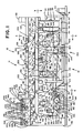
- a transport mechanism that incorporates the instant invention is shown generally at 10 and is used in conjunction with a scale 12 for the purpose of transporting flats, such as envelopes, across the scale as will be described hereinafter.
- a frame 14 supports four uprights 16.
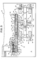
- a leaf spring 20 is attached by means of a cap 22 that can be bolted to the upright with a portion of the leaf spring held securely therebetween.
- the leaf springs 20 are formed at an angle and have a lower portion that is attached, by any convenient manner such as by bolts or by welding, to a base 24.
- the angle of the leaf spring is between approximately 1/2° and 15° relative to the vertical.
- Each flexible member 26 has a pair of opposed parallel flexible plates 28 joined together by integral connecting members 30.
- a transducer 33 is secured to at least one of the plates 28 of one of the flexible members 26. This transducer 33 may be a device such as a piezoelectric device (PZT) such that a voltage is generated in accordance with the bending of the transducer.
- PZT piezoelectric device
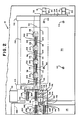
- Also secured to the springs 20 and base 24 are a pair of opposed plates 32 that support a beam 34.
- a tray 36 is attached to the flexible members 26 in any conventional manner such as bolt 40, soldering or welding.
- the tray 36 has a number of longitudinally extending slots 38 therein, but it will be appreciated that one extended opening is acceptable.
- the tray 36 has an additional opening 43 located downstream from the slots 38.
- An electromagnet 37 is supported by the beam 34 and receives an armature 41, made of electromagnetic material such as iron, that depends from the tray between the two poles 39 of the electromagnet.
- a bracket 42 is secured to the frame 14 and has an opening 44 therein.
- a reversible DC motor 46 is attached to the bracket 42, the output shaft of 48 of the motor being received within the opening 44.
- the motor 46 is operative to be rotated continuously in one direction and a selected amount, such as a single revolution, in the other direction.
- Attached to the output shaft 48 are a gear 50 and a drive pulley 52.
- a bracket 54 has an opening 56 therein and a counterbore 58 located adjacent the opening 56.
- a pin 55 is supported by the bracket 54 and the pin has a pulley 57 rotatably mounted thereon.
- a finger 60 depends from a generally U-shaped carriage 62 and the finger is received within the opening 56 of the bracket 54.
- a coil spring 66 is mounted about the finger 60 intermediate the carriage 62 and counterbore 58 to urge the carriage away from the bracket 54.
- the carriage 62 is elongated and has a pair of walls 68,69 with projections 70, the projections of the wall 68 addressing the viewer in Fig.
- a plurality of pins 72 is supported by the projections 70 of the carriage 62 and a roller 74 is rotatably mounted upon each pin 72. As seen in Figs. 1, six rollers 74 are supported by the carriage 62. Three pins 76 are attached to the wall 69 and rotatably support pulleys 78 thereon.
- a pin 82 is supported by the bracket 42 and has mounted thereon a one way clutch 84 about which is mounted a gear 86, the gear 86 meshing with the motor gear 50.
- An idler pulley 88 is rotatably supported by the pin 82.
- Another pin 90 is supported by the bracket 42 and has rotatably mounted thereon a pivot arm 92.
- a spring 94 is attached to the pivot arm 92 and supported by a mounting 96 that is attached to the bracket 42. In this manner the pivot arm 92 is urged by the spring 94 in a counter clockwise direction as seen in Fig. 1.
- a pin 98 is located on the end of the pivot arm 92 distal from the pin 90 and has an idler pulley 100 rotatably mounted thereon.
- Another pin 102 is supported by the bracket 42 and has an idler pulley 104 rotatably mounted thereon.
- Still another pin 106 is mounted on the bracket 42 and has an idler pulley 108 supported thereon.
- a belt 110 is trained about the rollers 74 and the pulleys 52, 57,78,88,98,104,108 in a serpentine fashion.
- the belt 110 is trained about a first roller 74 and a pulley 78 and then extends from a second roller to a third roller 74 before being trained about another pulley 78, and then once more extends from the fourth and fifth rollers 74 before being trained about the other pulley 78, and finally trained about the sixth roller 74.
- the reason for having this particular configuration of the belt is for the purpose of reducing wear on the belt. Having the belt extending laterally to two adjacent rollers 74 has been found to substantially reduce the wear of the belt as opposed to having the belt train alternatively about combinations of rollers 74 and pulleys 78 throughout.
- a pair of generally C-shaped supports 112 are attached to the tray 36 at opposite longitudinal ends thereof and support a bar 114 that extends longitudinally above the tray 36.
- the bar 114 has a number of pins 116 mounted thereon each pin supporting an arm 118.
- Each arm 118 has a paddle 120 at one end and a notch 122 at its other end.
- a spring 124 is mounted upon each pin 116 and has one tang 26 received within the notch 122 of an arm 118 and another tang 128 in engagement with the underside of the bar 114.
- This spring 124 provides a biasing force against the arms 118 that urges the paddles 120 into engagement with the portion of the belt 110 that is trained about the rollers 74 or into engagement with a flat 130 being transported across the tray 36.
- the paddles 120 are laterally larger than the slots 38 in the tray 36 thereby preventing the arms from falling into the slots when the rollers 74 are removed as will hereinafter be described.
- Supported by the frame 14 by any convenient manner is a photodetector unit 129 that directs lights into the opening 43 and senses reflected light when an object such as a flat is on the tray 36.
- a wall 132 has a plate 134 mounted thereon, the plate 134 having four slots 136 therein.
- a pair of shafts 138,140 are supported by the plate 134 so as to be received within and extend across the slots 136.
- a pin 140 is attached to each of the shafts 138 and a pair of arms 141 is attached to each of the shafts 138. It will be noted that two of the arms 141 are in longitudinal alignment with the arms 118 while the other two arms 141 are off-set.
- Each of the arms 141 has a paddle 142 that is directed towards an associated roller 74 on one of the arms and toward the plate 134 on the other three arms by a combination of spring 124 notch 122 and tangs 126,128 as described previously with respect to the other arms 118.
- a channel member 144 is supported by the plate 134 and has an opening 145 therein, as well as a T-shaped channel 146 that receives a generally T-shaped slide 148 that has a pusher 152 extending therefrom which is received within the opening 145.
- a pair of fingers 154 depend from the T-shaped slide 148 and are engageable with the pins 140.
- a solenoid 156 is supported by the channel member 144, the push rod 158 of the solenoid engaging the pusher 152.
- a locking mechanism is shown generally at 159 and includes a bracket 160 that is supported by the frame 14 and has a pair of pins 162 extending therefrom.
- a generally L-shaped arm 164 is pivotally mounted on each pin 162, each of the L-shaped arms 164 having a projection 165, the two projections extending towards one another and spaced from one another.
- the ends of the L-shaped arms each has a slot 166 therein.
- a finger 167 depends from the beam 34, see Fig. 3, to be received between the two projections 165.
- a pin 168 is received within the arm slots 166, the pin being secured to a lever 170 that is rotatably supported by a pin 174 attached to a stanchion 172.
- the stanchion 172 is secured to the frame 14.
- a pusher 176 is fixed to the carriage 62 and a compression spring 178 is attached, by any convenient manner, to the frame 14 at one of its ends and engages the lever 170 at its other end so as to urge the lever towards the pusher 176.
- the circuitry for the combination scale and and transporting mechanism includes an electronic controller 182 that is in communication with a computer 184 as well as the photodetector unit 129, the PZT 33 and the electromagnet 37.
- the computer 184 in turn is connected to a motor controller 186 which in turn is connected to the motor 46 to control drive of the latter upon receiving instruction from the computer.
- a flat 130 such as an envelope
- it is initially placed by a convenient method between the rollers 74 on the left side of the mechanism as seen in Fig. 1, and two of the paddles 142 of the arms 141 and between the tray 36 and two of the paddles 142.
- the presence of the additional arms 141 is for guiding the flat 130 onto the tray 36 and providing linkage with an upstream module or device or they serve the function of sealing the flap of the envelope.
- the motor 46 is operated so as to rotate the pulley 52 continuously in the counter clockwise direction as seen in Fig. 1, and the pulley 88 will perform as an idler pulley to rotate in a counter clockwise direction because the one way clutch 84 is not engaged under these circumstances.
- the endless belt 110 will cause the rollers 74 to rotate in the clockwise direction so that the belt has the movement at the top of the rollers 74 from left to right as seen in Fig. 1. It will be appreciated all the idler pulleys 57,78,98,104, and 108 will be driven as well.
- the flat 130 is placed between the paddles 142 and the belt 110 and will be conveyed across the tray 36 until the leading edge of the flat is located above the photodetector unit 129 where it will be sensed. As a result of this sensing, the motor 46 will be disabled, thereby discontinuing the drive to the belt 110 and the motor will be enabled for reverse drive. As the shaft 48 is rotated in the clockwise direction, as seen in Fig. 1, the gear 50 will drive the gear 86 and the one way clutch 84 will engage the shaft 82 to cause the pulley 88 to rotate in the same direction, i.e. counter clockwise.
- the belt 110 With the pulley 88 driven in the counter clockwise direction and the pulley 52 driven in the clockwise direction, the belt 110 will be pulled inwardly by the two pulleys 52,88 as indicated by the dotted arrows in Fig. 1 so as to place a force upon the rollers 74. This will cause the carriage 62 to be pulled downwardly against the spring 66 until the rollers 74 lose contact with the flat 130, i.e. , below the surface of the tray 36.
- the spring 94 will act upon the lever 92 to cause the pulley 100 to be moved away from the pulley 104 to take up the slack in the belt 110 caused by the action of the pulleys 52,88 that results in a new location of the carriage 62.
- the solenoid 156 With the carriage 62 pulled to the downward position, the solenoid 156 will be actuated so that the ram 158 pushes the pusher 152 to the left as seen in Fig. 1 whereby the fingers 154 will contact the pins 140 to cause the arms 141 to pivot about the shafts 138.
- the tray 36 While the above is occurring, the tray 36 will be in a locked position by virtue of the projections 165 being in contact with the finger 167 that depends from the tray 36, see Fig. 5.
- the motor 46 is reverse driven to cause the belt 110 to pull the carriage 62 downwardly and overcome the springs 58, the pusher 176 will act upon the lever 170 causing the pin 68 to be moved, in a clockwise direction, virtually vertically, downwardly, thereby causing the arms 164 to rotate as indicated by the arrows in Fig. 5.
- the projections 165 are withdrawn from the finger 167 thereby unlocking the tray 36.
- One of the advantages of the locking mechanism 159 is that it cooperates with the movement of the carriage 62 to assure coordination between the two.
- the electromagnet 37 Upon the tray being unlocked, the electromagnet 37 will be activated thereby causing the armature 41 to be attracted by one of the poles 39 of the electromagnet and repulsed by the other pole thereby giving the tray an impulse that causes vibration of the tray and bending of the flexible members 26. As the flexible members 26 are flexed as a result of the impulse to the tray 36, the transducer 33 will be repeatedly bent and emit a signal representing simple harmonic motion of the tray. Based upon the zero zero frequency crossings, the weight of the object on the tray can be determined. The details as to how the scale 12 obtains the weight from the simple harmonic motion of the tray is fully explained US-4 778 018, and for that reason the principle of weight determination will not be described herein. With the weight being determined by the computer 184, the computer will then give instructions to the motor controller 186 and the solenoid 156, as will be described.
- the motor 46 is caused to be driven in the drive direction such that the pulley 52 will once more be rotated continuously in the counter clockwise direction.
- the gear 50 causes gear 86 to rotate in the clockwise direction, which is the direction in which the one way clutch provides no drive to the shaft 82 thereby causing the pulley 88 to be idle, i.e., free wheeling.
- This will result in the belt 110 being driven in the clockwise direction so that that portion of the belt trained about the pulleys 52,88,100 and 102 will be pulled inwardly to contract, and the spring 66 will urge the carriage 62 upwardly.
- the plunger 176 will be moved away from the lever 170 thereby allowing the spring 178 to drive the lever in a counter clockwise direction.
- the pin 168 within the slots 166 will cause the arms 164 to move in a direction opposite to the arrows shown in Fig. 5 thereby bringing the projections 165 into contact with the finger 167 to lock the tray 36 once more.
- the solenoid 156 will be deactivated, thereby removing the plunger 158 from contact with the pusher 152 thereby allowing the springs 124 to rotate the arms 141 in a clockwise direction, thus pushing the T-shaped slide to the right as seen in Fig.
- the transporting apparatus is ready to remove a flat that has been weighed and transport another flat onto the tray 136. Such removal is accomplished by the motor 46 being enabled to drive the belt 110 in the counterclockwise direction.
- a transporting mechanism 10 whereby flats can be readily transported onto a tray 36 of a scale and the portion of the transporting system not associated with the tray will be removed therefrom to allow free oscillation of the tray for the purpose of weighing the flat.
Landscapes
- Physics & Mathematics (AREA)
- General Physics & Mathematics (AREA)
- Mathematical Physics (AREA)
- Sorting Of Articles (AREA)
- Delivering By Means Of Belts And Rollers (AREA)
- Packaging Of Special Articles (AREA)
- Closing Of Containers (AREA)
- Discharge Of Articles From Conveyors (AREA)
Priority Applications (1)
| Application Number | Priority Date | Filing Date | Title |
|---|---|---|---|
| EP93111358A EP0570025B1 (de) | 1988-12-29 | 1989-11-09 | Transport-Vorrichtung zum Transportieren eines flachen Artikels auf eine und von einer Waagschale |
Applications Claiming Priority (2)
| Application Number | Priority Date | Filing Date | Title |
|---|---|---|---|
| US07/290,349 US4844188A (en) | 1988-12-29 | 1988-12-29 | Apparatus and method of transporting flats across a scale |
| US290349 | 1988-12-29 |
Related Child Applications (2)
| Application Number | Title | Priority Date | Filing Date |
|---|---|---|---|
| EP93111358.3 Division-Into | 1989-11-09 | ||
| EP93111358A Division EP0570025B1 (de) | 1988-12-29 | 1989-11-09 | Transport-Vorrichtung zum Transportieren eines flachen Artikels auf eine und von einer Waagschale |
Publications (3)
| Publication Number | Publication Date |
|---|---|
| EP0376454A2 true EP0376454A2 (de) | 1990-07-04 |
| EP0376454A3 EP0376454A3 (de) | 1991-08-21 |
| EP0376454B1 EP0376454B1 (de) | 1994-03-02 |
Family
ID=23115584
Family Applications (2)
| Application Number | Title | Priority Date | Filing Date |
|---|---|---|---|
| EP93111358A Expired - Lifetime EP0570025B1 (de) | 1988-12-29 | 1989-11-09 | Transport-Vorrichtung zum Transportieren eines flachen Artikels auf eine und von einer Waagschale |
| EP89311602A Expired - Lifetime EP0376454B1 (de) | 1988-12-29 | 1989-11-09 | Kombination einer Transportvorrichtung und einer Waage für flache Artikel |
Family Applications Before (1)
| Application Number | Title | Priority Date | Filing Date |
|---|---|---|---|
| EP93111358A Expired - Lifetime EP0570025B1 (de) | 1988-12-29 | 1989-11-09 | Transport-Vorrichtung zum Transportieren eines flachen Artikels auf eine und von einer Waagschale |
Country Status (5)
| Country | Link |
|---|---|
| US (1) | US4844188A (de) |
| EP (2) | EP0570025B1 (de) |
| AU (1) | AU624294B2 (de) |
| CA (1) | CA2002216C (de) |
| DE (2) | DE68925486T2 (de) |
Families Citing this family (5)
| Publication number | Priority date | Publication date | Assignee | Title |
|---|---|---|---|---|
| US5109937A (en) * | 1990-12-21 | 1992-05-05 | Pitney Bowes Inc. | Transport mechanism for a weighing scale |
| US5256835A (en) * | 1992-07-31 | 1993-10-26 | Pitney Bowes Inc. | Software control of a weigh and feed transport in a weighing module |
| FR2800162B1 (fr) * | 1999-10-25 | 2002-01-11 | Neopost Ind | Dispositif de guidage et de maintien d'articles de courrier |
| US6762370B2 (en) * | 2002-05-02 | 2004-07-13 | Pitney Bowes Inc. | Vibrating tray scale having a clamping device that allows for detection of loose matter in a mail piece |
| US6769862B1 (en) | 2002-12-03 | 2004-08-03 | Jeffrey B. Kuhl | Apparatus and method for placing horizontally oriented flats into vertically extending stacks thereof |
Family Cites Families (6)
| Publication number | Priority date | Publication date | Assignee | Title |
|---|---|---|---|---|
| US3119457A (en) * | 1959-06-30 | 1964-01-28 | Fmc Corp | Weight checking apparatus |
| CH412373A (de) * | 1963-10-21 | 1966-04-30 | Hesser Ag Maschf | Kontrollwaage |
| US4049068A (en) * | 1976-05-03 | 1977-09-20 | Hi-Speed Checkweigher Co., Inc. | Price labeling system with floating zero reference |
| US4778018A (en) * | 1987-07-13 | 1988-10-18 | Pitney Bowes Inc. | Apparatus and method of determining the mass of an article by measuring the shift in the period of harmonic motion |
| GB2213756B (en) * | 1987-12-17 | 1992-09-30 | Pitney Bowes Inc | Cutter module for a modular mailing machine |
| US4842084A (en) * | 1988-12-29 | 1989-06-27 | Pitney Bowes Inc. | Locking mechanism for a weighing scale tray |
-
1988
- 1988-12-29 US US07/290,349 patent/US4844188A/en not_active Expired - Lifetime
-
1989
- 1989-11-03 CA CA002002216A patent/CA2002216C/en not_active Expired - Fee Related
- 1989-11-09 DE DE68925486T patent/DE68925486T2/de not_active Expired - Fee Related
- 1989-11-09 EP EP93111358A patent/EP0570025B1/de not_active Expired - Lifetime
- 1989-11-09 DE DE68913484T patent/DE68913484T2/de not_active Expired - Fee Related
- 1989-11-09 EP EP89311602A patent/EP0376454B1/de not_active Expired - Lifetime
- 1989-11-10 AU AU44545/89A patent/AU624294B2/en not_active Ceased
Also Published As
| Publication number | Publication date |
|---|---|
| US4844188A (en) | 1989-07-04 |
| EP0570025A1 (de) | 1993-11-18 |
| CA2002216A1 (en) | 1990-06-29 |
| DE68913484D1 (de) | 1994-04-07 |
| AU4454589A (en) | 1990-07-05 |
| AU624294B2 (en) | 1992-06-04 |
| DE68925486D1 (de) | 1996-02-29 |
| CA2002216C (en) | 2000-10-10 |
| EP0376454A3 (de) | 1991-08-21 |
| DE68925486T2 (de) | 1996-05-30 |
| EP0376454B1 (de) | 1994-03-02 |
| DE68913484T2 (de) | 1994-06-01 |
| EP0570025B1 (de) | 1996-01-17 |
Similar Documents
| Publication | Publication Date | Title |
|---|---|---|
| AU615674B2 (en) | Apparatus and method of determining the mass of an article by measuring the shift in the period of harmonic motion | |
| EP0176662B1 (de) | Dehnfolienverpackungsmaschine | |
| US4848492A (en) | Transporting and drive mechanism for a weighing scale | |
| US2840223A (en) | Article feeding means | |
| US4981292A (en) | Swing-up loader for signature machines | |
| US5292114A (en) | Automatic feeder module for a mail sorting system | |
| EP0376454B1 (de) | Kombination einer Transportvorrichtung und einer Waage für flache Artikel | |
| US4842084A (en) | Locking mechanism for a weighing scale tray | |
| US3732966A (en) | Packaging apparatus | |
| US5109937A (en) | Transport mechanism for a weighing scale | |
| US4836311A (en) | Oscillating and locking apparatus and method for vibrating tray weighing scale | |
| US4856602A (en) | Apparatus and method of weighing articles based upon harmonic motion | |
| US4326704A (en) | Tipping machine | |
| US4460428A (en) | Scaling and labeling apparatus | |
| SE431081B (sv) | Sett och apparat for att limma dokument pa en kontinuerlig berarbana | |
| US4903788A (en) | Vibrating tray scale with conveying mechanism | |
| US4925006A (en) | Conveyor apparatus having means for a shock-free article acceleration | |
| CN216807419U (zh) | 发卡机的托料机构及采用该托料机构的发卡机 | |
| EP0581617A1 (de) | Elektronische Postwaage mit variablem Förderband | |
| EP0572181A1 (de) | Verriegelungsmechanismus für eine Schwingungswaage | |
| US3330715A (en) | Apparatus for applying adhesive patterns to flat cardboard elements | |
| US4836313A (en) | Oscillating and locking apparatus and method for vibrating tray weighing scale | |
| US4877346A (en) | Sheet feed hopper for insertion machine | |
| JP2935586B2 (ja) | シート状材定量供給装置 | |
| US5060741A (en) | Platen module for a modular mailing machine |
Legal Events
| Date | Code | Title | Description |
|---|---|---|---|
| PUAI | Public reference made under article 153(3) epc to a published international application that has entered the european phase |
Free format text: ORIGINAL CODE: 0009012 |
|
| AK | Designated contracting states |
Kind code of ref document: A2 Designated state(s): CH DE FR GB LI |
|
| PUAL | Search report despatched |
Free format text: ORIGINAL CODE: 0009013 |
|
| AK | Designated contracting states |
Kind code of ref document: A3 Designated state(s): CH DE FR GB LI |
|
| RHK1 | Main classification (correction) |
Ipc: G01G 11/04 |
|
| 17P | Request for examination filed |
Effective date: 19920127 |
|
| 17Q | First examination report despatched |
Effective date: 19930202 |
|
| GRAA | (expected) grant |
Free format text: ORIGINAL CODE: 0009210 |
|
| AK | Designated contracting states |
Kind code of ref document: B1 Designated state(s): CH DE FR GB LI |
|
| REF | Corresponds to: |
Ref document number: 68913484 Country of ref document: DE Date of ref document: 19940407 |
|
| ET | Fr: translation filed | ||
| PLBE | No opposition filed within time limit |
Free format text: ORIGINAL CODE: 0009261 |
|
| STAA | Information on the status of an ep patent application or granted ep patent |
Free format text: STATUS: NO OPPOSITION FILED WITHIN TIME LIMIT |
|
| 26N | No opposition filed | ||
| REG | Reference to a national code |
Ref country code: GB Ref legal event code: IF02 |
|
| PGFP | Annual fee paid to national office [announced via postgrant information from national office to epo] |
Ref country code: GB Payment date: 20031105 Year of fee payment: 15 |
|
| PGFP | Annual fee paid to national office [announced via postgrant information from national office to epo] |
Ref country code: FR Payment date: 20031119 Year of fee payment: 15 |
|
| PGFP | Annual fee paid to national office [announced via postgrant information from national office to epo] |
Ref country code: CH Payment date: 20031121 Year of fee payment: 15 |
|
| PGFP | Annual fee paid to national office [announced via postgrant information from national office to epo] |
Ref country code: DE Payment date: 20031231 Year of fee payment: 15 |
|
| PG25 | Lapsed in a contracting state [announced via postgrant information from national office to epo] |
Ref country code: GB Free format text: LAPSE BECAUSE OF NON-PAYMENT OF DUE FEES Effective date: 20041109 |
|
| PG25 | Lapsed in a contracting state [announced via postgrant information from national office to epo] |
Ref country code: LI Free format text: LAPSE BECAUSE OF NON-PAYMENT OF DUE FEES Effective date: 20041130 Ref country code: CH Free format text: LAPSE BECAUSE OF NON-PAYMENT OF DUE FEES Effective date: 20041130 |
|
| PG25 | Lapsed in a contracting state [announced via postgrant information from national office to epo] |
Ref country code: DE Free format text: LAPSE BECAUSE OF NON-PAYMENT OF DUE FEES Effective date: 20050601 |
|
| GBPC | Gb: european patent ceased through non-payment of renewal fee |
Effective date: 20041109 |
|
| REG | Reference to a national code |
Ref country code: CH Ref legal event code: PL |
|
| PG25 | Lapsed in a contracting state [announced via postgrant information from national office to epo] |
Ref country code: FR Free format text: LAPSE BECAUSE OF NON-PAYMENT OF DUE FEES Effective date: 20050729 |
|
| REG | Reference to a national code |
Ref country code: FR Ref legal event code: ST |