EP0376528A2 - Verriegelungsvorrichtung für abnehmbare Frankiermaschine - Google Patents
Verriegelungsvorrichtung für abnehmbare Frankiermaschine Download PDFInfo
- Publication number
- EP0376528A2 EP0376528A2 EP89312862A EP89312862A EP0376528A2 EP 0376528 A2 EP0376528 A2 EP 0376528A2 EP 89312862 A EP89312862 A EP 89312862A EP 89312862 A EP89312862 A EP 89312862A EP 0376528 A2 EP0376528 A2 EP 0376528A2
- Authority
- EP
- European Patent Office
- Prior art keywords
- meter
- cover
- housing
- locking
- aperture
- Prior art date
- Legal status (The legal status is an assumption and is not a legal conclusion. Google has not performed a legal analysis and makes no representation as to the accuracy of the status listed.)
- Granted
Links
- 230000004044 response Effects 0.000 claims description 5
- 239000000463 material Substances 0.000 claims description 3
- 230000008878 coupling Effects 0.000 claims description 2
- 238000010168 coupling process Methods 0.000 claims description 2
- 238000005859 coupling reaction Methods 0.000 claims description 2
- 230000000007 visual effect Effects 0.000 claims description 2
- 230000007246 mechanism Effects 0.000 abstract description 7
- 239000000969 carrier Substances 0.000 description 12
- 230000001276 controlling effect Effects 0.000 description 9
- 230000000875 corresponding effect Effects 0.000 description 4
- 230000003287 optical effect Effects 0.000 description 3
- 241001131688 Coracias garrulus Species 0.000 description 2
- 230000009471 action Effects 0.000 description 2
- 238000010586 diagram Methods 0.000 description 2
- 230000005484 gravity Effects 0.000 description 2
- 230000013011 mating Effects 0.000 description 2
- 230000004048 modification Effects 0.000 description 2
- 238000012986 modification Methods 0.000 description 2
- IJJWOSAXNHWBPR-HUBLWGQQSA-N 5-[(3as,4s,6ar)-2-oxo-1,3,3a,4,6,6a-hexahydrothieno[3,4-d]imidazol-4-yl]-n-(6-hydrazinyl-6-oxohexyl)pentanamide Chemical compound N1C(=O)N[C@@H]2[C@H](CCCCC(=O)NCCCCCC(=O)NN)SC[C@@H]21 IJJWOSAXNHWBPR-HUBLWGQQSA-N 0.000 description 1
- 230000005355 Hall effect Effects 0.000 description 1
- 230000000712 assembly Effects 0.000 description 1
- 238000000429 assembly Methods 0.000 description 1
- 229940000425 combination drug Drugs 0.000 description 1
- 239000006260 foam Substances 0.000 description 1
- 238000007689 inspection Methods 0.000 description 1
- 230000002265 prevention Effects 0.000 description 1
- 230000000717 retained effect Effects 0.000 description 1
Images


Classifications
-
- G—PHYSICS
- G07—CHECKING-DEVICES
- G07B—TICKET-ISSUING APPARATUS; FARE-REGISTERING APPARATUS; FRANKING APPARATUS
- G07B17/00—Franking apparatus
- G07B17/00185—Details internally of apparatus in a franking system, e.g. franking machine at customer or apparatus at post office
- G07B17/00193—Constructional details of apparatus in a franking system
- G07B2017/00233—Housing, e.g. lock or hardened casing
Definitions
- the invention relates to meters, more particular strictlyly flat-bed printing meters, and to security and control devices therefor.
- Die protection assemblies incorporate various mechanical arms or projections which protrude from the printwheel area of the die in order to prevent a person from simply placing an envelope against the die to obtain an imprint.
- US-A-2795186 issued to Bach shows a movable shroud which can be lowered to guard the printing die against taking unauthorized impressions at any time between printing operations.
- the shroud completely covers the face of the value printing die when the printing mechanism is not in an operating cycle and is locked in that position until the cycle starts at which time the shroud is moved to a position uncovering the die.
- US-A-4559444 teaches an interposer arrangement which extends upward from the platen into the space into which an envelope or other workpiece is to be inserted. These interposers are moved out of the way during a legitimate printing operation.
- interposer blades are mechanically linked to the inking mechanism in order to move the blades out of the way as the mailpiece moves into position for imprinting.
- US-A-4796526 and US-A-4796527 describe interposer devices which are linked to the motor driving the platen of the printer to move out of the way or actuated by a power switch to be moved out of the way so long as power is applied to the machine.
- the present invention provides combinations of a postage meter including the movable cover, a locking device for the cover, a receptacle, locking device or base for the postage meter, and means performing one or more of the functions described herein; specifically, sensing loading and locking of the postage meter into the base, sensing positioning of postage meter in a predetermined position in the base, sensing the status of the movable postage meter cover, moving the postage meter cover, locking and unlocking the postage meter cover, unlocking the postage meter from the base and sensing same, and performing certain functions in response to a keyswitch and/or a control system.
- the postage meter comprises a housing, a printing device disposed in the housing, an aperture in the housing exposing the printing device to the exterior of the housing, a cover for the aperture, means mounting the cover to the postage meter for movement of the cover from a closed position in which the cover is disposed at the aperture denying access to the printing device, and an open position in which the cover is disposed away from the aperture.
- the cover is struc tured to prevent access to the printing device when the cover is in the open position and to permit access to the printing device when the cover is in the open position, and the receptacle includes first engaging means for engaging the cover in a predetermined position of the postage meter, and driving means for driving the first engaging means to move the cover between the closed and open positions thereof.
- the receptacle or base com strictlyprises a first receptacle part (e.g., a meter pocket) and second receptacle part (e.g., a locking device) and means coupling the first and second receptacle parts together such that the first receptacle part is pivotal between a first position thereof in which the first receptacle part forms an angle with the second receptacle part and a second position thereof in which the first receptacle part is within the second receptacle part.
- first receptacle part e.g., a meter pocket
- second receptacle part e.g., a locking device
- the first receptacle part includes means for receiving a first end of the postage meter therein when the first receptacle part is in the first position
- the second receptacle part includes second engaging means for engaging a second end of the postage meter therein when the first receptacle part is in its second position within the first receptacle part.
- the first engaging means and the driving means are mounted to the second receptacle part.
- One combination of the invention comprises the locking device which includes means for locking the postage meter therein in a predetermined position thereof, first engaging means for engaging the postage meter cover in the predetermined position of the postage meter, and driving means for driving the first engaging means to move the cover between the closed and open positions thereof; and a control system which comprises means for determining when the postage meter is locked in the predetermined position and means for controlling the driving means.
- the controlling means permits the driving means to move the cover only when the postage meter is locked in the predetermined position.
- control system comprises a key settable switch having a plurality of switch positions set by a key and means for controlling the driving means in response to the positions of the switch, the controlling means causing the driving means to move the cover from the closed position to the open position when the postage meter is in the predetermined position and the switch is switched from a first state thereof to a second state thereof.
- Another combination of the invention comprises a postage meter locking device which includes locking means for locking the postage meter therein in a predetermined position thereof and means for actuating the locking means to lock and unlock the postage meter; and a control system which comprises a key settable switch having a plurality of switch positions set by a key and means for controlling the actuating means to cause the actuating means to unlock the postage meter when the switch is switched from a first state thereof to a second state thereof.
- Another combination comprises a postage meter locking device which includes the locking means, the driving means for driving the first engaging means and the means for actuating the locking means to lock and unlock the postage meter; and a control system which comprises a key settable switch having a plurality of switch positions set by a key, means for controlling the driving means in response to the positions of the switch, the controlling means causing the driving means to move the cover from the closed position to the open position when the postage meter is in the predetermined position and the switch is switched from a first state thereof to a second state thereof, and means for controlling the actuating means to cause the actuating means to unlock the postage meter when the switch is switched to the first state thereof from another state thereof.
- a locking means disposed in the postage meter for selectively locking the cover may also be provided which is actuable by the control system when the switch is switched from the first state to another state thereof.
- the invention also provides a housing for the switch and tamper resistant means for attaching the housing to the postage meter device.
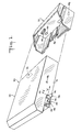
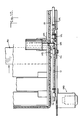
- postage meter 20 is insertable and removable from postage meter pocket 22, which in turn is pivotally mounted to postage meter locking device 24 (Fig. 3).
- Meter pocket 22 and locking device 24 form a base for postage meter 20.
- Postage meter 20 includes a printing device 26 (Fig. 16) for printing postage indicia and related indicia such as a town seal, slogans, advertising, etc., and circuitry and structure for setting printing device 26 to print desired indicia, entering authorized postage amounts, and for record keeping of various items such as postage dispensed, postage remaining, etc.
- Locking device 24 in the disclosed embodiment forms part of a mailing machine 26 (Fig.
- Postage meter 20, meter pocket 22 and locking device 24 may also be constructed as a module to be utilized alone or as part of a larger machine.
- Postage meter 20 and meter pocket 22 include mating connectors 32, 33 by means of which signals are exchanged between postage meter 20, locking device 24, and, in the disclosed embodiment, among meter 20, locking device 24 and mailing machine 26. Connectors 32, 33 also supply power to postage meter 20.
- postage meter 20 and meter pocket 22 include mating dovetail structure 35, 36 for aligning postage meter 20 in meter pocket 22 so that connectors 32 and 33 electrically and mechanically engage when meter 20 is fully seated in pocket 22.
- Postage meter 20 may be unseated from meter pocket 22 (see Fig. 1) and removed for postage entry, inspection, servicing, etc., or for gaining access to parts of mailing machine 26 for servicing, ink cartridge replacement, etc.
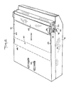
- postage meter 20 includes a shutter bar or cover 40 which in its closed position (Fig. 2) covers print die 29 to protect same, to prevent unauthorized use of meter 20 and to inhibit tampering.
- Shutter bar 40 is movable to its open position, illustrated by broken lines in Fig. 2, at the ends 42 of shutter bar guide slots 43 to expose print die 29.
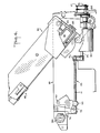
- meter 20 is loaded and locked into and by locking device 24 by first seating meter 20 in pocket 24 (Figs. 3 and 4), and then pivoting meter 20 seated in pocket 22 into locking device 24 (Fig. 5).
- shutter bar 40 may be retracted to its open position (to the right in Fig. 5) by drive mechanism 45 ready to imprint postage indicia on mail pieces and/or tape.
- postage meter 20 When inserted for use in mailing machine 26, postage meter 20 must be accurately positioned relative to the mailing machine particularly for high speed operation of the mailing machine. Locking device 24 and postage meter 20 are therefore provided with means for accurately positioning postage meter 20 along two axes which in the disclosed embodiments are designated as the "x" axis (horizontal) and the “y” axis (vertical).
- postage meter 20 includes a locking section 50 disposed on each side 51, 52 of meter 20. Locking sec tion 50 has an "x" axis cam surface 53 and a "y" axis cam surface 54. Locking device 24 includes an "x" axis cam pin 55 (Fig.
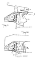
- Locking device 24 also includes pivotally mounted latching lever 60 (Fig. 13) having a "y" axis cam 62 which engages "y" axis cam surface 54 to cam postage meter 20 accurately into its seated position with respect to the "y" axis.
- a sensing system including send and receive optical sensors 71, 72 (Fig. 11) in locking device 24 cooperate with corresponding sensors 73, 74 (Fig. 16) in postage meter 20 to verify that postage meter 20 is accurately positioned with respect to the "x" and "y" axes.
- the sensors also exchange other information, for example, handshaking information between postage meter 20 and mailing machine 26, and may be used to monitor loading and removal of postage meter 20 from locking device 24.
- meter pocket 22 is mounted to locking device 24 by a counterbalance mechanism 80 which includes counterbalance arm 82 fixed to torsion bar 84 (Fig. 7). Pivoting of arm 82 torsions the torsion bar 84 which resists pivoting and urges arm 84 back to its rest position depicted in Fig. 3.
- Roller 86 is rotatably mounted to end 88 of arm 82 to ride along cam surface 90 of counterbalance cam 92 attached to the bottom of meter pocket 22.
- postage meter 20 is inserted into meter pocket 20, as illustrated by Figs.
- meter 20 and pocket 22 are pivoted against the force of counterbalance torsion bar 84 to lower meter 20 into locking device 24 into the position depicted in Fig. 5.
- Postage meter 20 and meter pocket 22 are mechanically locked in locking device 24 by engagement of cam 54 (Fig. 5) urged upwardly by the action of torsion bar 84 against cam surface 62 of latching lever 60.
- latching lever 60 is pivoted clockwise by pin 96 sliding along surface 100 of latching lever 60.
- pin 96 slides past surface 100 (Fig. 13) and reaches surface 98, latching lever 60 pivots counterclockwise until it is engaged by pin 96 (Fig. 5).
- Latching lever 60 is configured and pivoted from locking device 24 to be suspended under the force of gravity in the position depicted in Fig. 13.
- latching lever 60 pivots from the Fig. 12 to the Fig. 13 position under the force of gravity.
- Postage meter 20 is removed from locking device 24 by causing latching lever 60 to be pivoted clockwise from the Fig. 5 position, as described below, thereby permitting counterbalance torsion bar 84 to pivot counterbalance arm 82 clockwise.
- Clockwise pivoting of arm 82 causes counterbalance cam 93 to follow roller 86 and move meter 20 and pocket 22 to the right from the Fig. 5 position to the point 102 on camming surface 90.
- Cam surface 90 is configured so that meter 20 and pocket 22 rise under the action of torsion bar 84 about 1 inch after latching lever 60 is disengaged from cam 54. This indicates to an operator that meter 20 is unlocked and may be removed by further pivoting the meter to the 45 degree position depicted in Fig. 2, and withdrawing it from meter pocket 22.
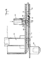
- drive mechanism 45 for moving shutter bar 40 between its open and closed positions comprises, on each side of locking device 24, a shutter bar carrier 110, lead screw 111, belt coupler 112, shaft 114, belt couplers 116, 117 and drive motor 120.
- Bearing 121 supports lead screws 111.
- Shutter bar carriers 110 engage shutter bar 45 and upon rotation of lead screws 111 move shutter bar 45.
- Shutter bar carriers 110 include a prong or projection 94 (Fig. 7) which is received between prongs 126 (Figs. 1 and 2) of shutter bar 40 for engaging shutter bar 40 to move it.
- Shutter bar carriers 110 are threaded to lead screws 111 which are rotated by motor 120 to advance shutter bar carriers 110 along lead screws 111.
- Motor 120 is coupled by belt couplers 116 and 117 to drive shafts 114 on each side of locking device 24.
- Each drive shaft 114 is in turn coupled to a lead screw 111 by another belt coupler 112.
- Belt couplers 112 are used to couple lead screws 111 and shafts 114, rather than having lead screw 111 run the full distance to belt couplers 116 and 117 in order to reduce the overall length of lead screws 111.
- Rotation of motor 120 causes the lead screws 111 on both sides of locking device 24 to rotate in synchronism and thereby advance shutter bar carriers 110 on each side of the locking device 24. As depicted in Fig. 5, shutter bar carriers 110 are moved to the right from the broken-line wait position, through the solid line position, to the broken line open position.
- solenoid 130 in postage meter 20 locks shutter bar 40 in the closed position depicted in Fig. 2.
- Shaft 132 of solenoid 130 includes larger diameter portions 134, 135 and smaller diameter portion 136 which define an annular groove between larger diameter portions 134, 135.
- Attached to shutter bar 40 within meter 20 is plate 140 (Fig. 5), which extends along the inside of side 51 of meter 20 to slide therealong as shutter bar 40 is moved between its open and closed positions.
- Plate 140 includes a narrow slot 142 therein which includes a larger circular part 143.
- larger diameter shaft portion 135 is aligned within the larger circular part 143 of plate 140.
- larger diameter shaft portion 135 engages narrow slot 142 of plate 140 to prevent sliding thereof relative to solenoid 130, and hence locks shutter bar 40 in its closed position illustrated in Fig. 8.
- Energization of drive motor 120 and solenoid 130 are controlled by key switch 150 mounted to locking device 24.
- Keyswitch 150 has three positions: “0", “1", “2". In the “0" position: no power is applied to drive motor 120 and solenoid 130; shutter bar 40 is locked in the closed position thereof depicted in Fig. 2; and shutter bar carrier 110 in locking device 24 is in the wait position depicted in Figs. 3, 4 and 7-9.
- power is applied to solenoid 130 to cause it to push shaft 132 thereof outwardly from the Fig. 8, to the Fig. 9 position. That unlocks shutter 40.
- Shutter bar 40 is opened by moving the switch key from the "0" to the "1” position, and remains in the open position any time that postage value selection is required. Moving the switch key from position "1" to “2” turns on the power to the postage meter 20. Postage meter 20 then checks the status of alignment sensors 170 and 171. If meter 20 is aligned, then printing may occur.
- postage meter 20 may imprint the same postage value on a large number of items, or for an entire mail run, so that resetting of the print die for different postage valves is unnecessary.
- locking device 24 includes sensors 160, 161 and one of shutter carriers 78 includes a strip on its bottom surface which interacts with the sensors.
- sensors 160, 161 are Hall-effect devices and a magnetic strip is affixed to the bottom of shutter carrier 78.
- the respective Hall device emits a signal when the magnetic strip is above it indicating the position of shutter carrier 78.
- Sensor 160 is positioned to detect shutter carrier 78 in its wait position (shutter bar 40 in its closed position) and sensor 161 is positioned to detect shutter carrier 78 in its advanced position.
- Keyswitch 150 and sensors 160 and 161 are coupled to a control system 165 (Fig. 16) either in locking device 24 or in mailing machine 20 which controls energization of drive motor 120 and solenoid 130 as described herein.
- Optical sensors 71 and 72 (Fig. 11) and the corresponding optical sensors 73, 74 (Fig. 16) in postage meter 20 are similarly coupled to that control system 165.
- latching lever 60 In order to remove postage meter 20 from locking device 24, latching lever 60 must be disengaged from cam 54 (Fig. 13). Latching lever 60 is pivoted in a sequence that is the reverse of the sequence depicted in Figs. 11-13 to release pin 96 from engagement with lever 60. That reverse pivoting sequence and position sensing of shutter carriers 78 and latching lever 60 are accomplished as follows.
- holes 170, 171 in frame 172 of locking device 24 are axially aligned with sensors 71 and 72 disposed in housing 175 of keyswitch 150 and sensors 73 and 74 disposed in postage meter 20.
- Holes 170, 171 are located adjacent latching lever 60 so as to be blocked by latching lever 60 when lever 60 is sufficiently pivoted.
- the control system may monitor pivoting of latching lever 60 during pivoting thereof, for example, in the sequence illustrated in Figs. 11-13.
- a shaft encoder 175 associated with drive motor 120 provides signals to the control system as to the angular position of motor shaft 176. Those signals used to determine the position of shutter carrier 78 after it passes sensor 160 and engages latching lever 60.
- shutter carriers 110 are moved from adjacent sensor 161 to adjacent sensor 160 to move shutter bar 40 to its closed position.
- drive motor 120 continues to advance shutter carrier 110 past sensor 160 into engagement with latching lever 60.
- sensor 160 emits a signal to control system 165.
- Control system 165 then accumulates signals emitted by the shaft encoder to track the further advance of shutter carrier 110.
- Shutter carrier 110 is advanced a predetermined distance to pivot latching lever 60 and also holes 170 and 171 are blocked by lever 60, which is sufficient to disengage cam 54 from lever 60 to release postage meter 20 as described above.
- control system 165 detects same and turns off the printer system to prevent accidental printing of postage. Pulses from shaft encoder 175 are again accumulated, and when the count is the same as the count at which motor 120 was reversed, motor 120 is stopped. This accurately repositions shutter carrier 78 in the wait position, ready for the next loading and locking of postage meter 20.
- Key switch 150 is constructed so that the key may be withdrawn in the "0" and “1" positions, but not in the “2" position. It is desirable not to be able to withdraw the key when switch 150 is in the "2" position to clearly indicate to an operator that shutter bar 40 is in the open position and that the postage meter is at a position of printing postage.
- key switch 150 incorporates security structure to inhibit tampering and to clearly provide a visual indication of tampering.
- Key switch 150 includes a housing 180 which is secured to locking device 24 by break-off screws 182 (Fig. 15).
- Break-off screws 182 include a slotted head 184 which receives a screwdriver to permit screw 182 to be tightened, and a smooth head 185.
- Head 184 is connected to head 185 by a weakened shaft 186. Screw thread 187 is attached to head 185.
- the slotted head 184 is torqued until weakened shaft 186 is sheared and slotted head 184 is separated from the screw. Smooth head 185 remains which can not be turned to prevent unscrewing. Therefore, housing 180 cannot be removed from locking device 24. Additionally, housing 180 is made of a deformable material such as plastic so that attempts to either remove it or break into it will be readily apparent.
- control system 165 is coupled to postage meter 20 through connector 33 of meter pocket 22 and connector 32 of postage meter 20.
- sensors 73 and 74 and solenoid 130 are coupled to control system 165.
- Locking device 24 is also coupled to control system 165.
- sensors 160, 161, sensors 71, 72, drive motor 120, shaft encoder 175 and keyswitch 150 are coupled to control system 165.
- Control system 165 receives information from sensors 71-74, 160 and 161 and from keyswitch 150, and controls energization of solenoid 130 to lock and unlock shutter bar 40.
- Control system 165 receives information from sensors 71-74 and determines whether postage meter 20 is properly in locking device 24 and when postage meter 20 has been inserted into and removed from locking device 24.
- Control system 165 receives information from keyswitch 150, 71, 72 and 160, and from shaft encoder 175, and controls drive motor 120 to cause latching lever 60 to be pivoted to release postage meter 20 from locking device 24, and to return shutter carriers 110 to the wait position.
- Control system 165 receives information from keyswitch 150 and sensors 160 and 161 to control drive motor 120 to move shutter carriers 110 to positions corresponding to the open and closed positions of shutter bar 40.
- Control system 165 may be constructed as described in the cited related applications to control functions described therein, and/or control system 165 may be constructed by those of skill in the art to perform functions described herein from the disclosure herein.
- the embodiment of the invention provides an improved system for locking and unlocking a cover of a postage meter movable to give access to a printing die of a printing device in the postage meter; provides an improved system for moving the cover between positions giving and denying access to the printing die; provides an improved receptacle or postage meter base for receiving a postage meter therein; provides a locking device or lockable postage meter base for receiving and locking therein a postage meter; provides such a receptacle and locking device which incorporates means for locking and unlocking the postage meter cover; provides such a receptacle and locking device which incorporates means for moving the postage meter cover between positions giving access and denying access to the printing die; provides a system for determining the position of a postage meter relative to a receptacle or base holding the postage meter; provides a system for determining the positional status of the postage meter cover referred to above; and provides a key actuated system which controls locking and unlock
Landscapes
- Physics & Mathematics (AREA)
- General Physics & Mathematics (AREA)
- Devices For Checking Fares Or Tickets At Control Points (AREA)
Priority Applications (1)
| Application Number | Priority Date | Filing Date | Title |
|---|---|---|---|
| EP94200482A EP0603169B1 (de) | 1988-12-28 | 1989-12-08 | Verriegelungsvorrichtung für abnehmbare Frankiermaschine |
Applications Claiming Priority (2)
| Application Number | Priority Date | Filing Date | Title |
|---|---|---|---|
| US291462 | 1988-12-28 | ||
| US07/291,462 US5049727A (en) | 1988-12-28 | 1988-12-28 | Locking device for removable postage meter |
Related Child Applications (2)
| Application Number | Title | Priority Date | Filing Date |
|---|---|---|---|
| EP94200482A Division EP0603169B1 (de) | 1988-12-28 | 1989-12-08 | Verriegelungsvorrichtung für abnehmbare Frankiermaschine |
| EP94200482.1 Division-Into | 1989-12-08 |
Publications (3)
| Publication Number | Publication Date |
|---|---|
| EP0376528A2 true EP0376528A2 (de) | 1990-07-04 |
| EP0376528A3 EP0376528A3 (en) | 1990-10-31 |
| EP0376528B1 EP0376528B1 (de) | 1995-03-08 |
Family
ID=23120393
Family Applications (2)
| Application Number | Title | Priority Date | Filing Date |
|---|---|---|---|
| EP89312862A Expired - Lifetime EP0376528B1 (de) | 1988-12-28 | 1989-12-08 | Verriegelungsvorrichtung für abnehmbare Frankiermaschine |
| EP94200482A Expired - Lifetime EP0603169B1 (de) | 1988-12-28 | 1989-12-08 | Verriegelungsvorrichtung für abnehmbare Frankiermaschine |
Family Applications After (1)
| Application Number | Title | Priority Date | Filing Date |
|---|---|---|---|
| EP94200482A Expired - Lifetime EP0603169B1 (de) | 1988-12-28 | 1989-12-08 | Verriegelungsvorrichtung für abnehmbare Frankiermaschine |
Country Status (5)
| Country | Link |
|---|---|
| US (1) | US5049727A (de) |
| EP (2) | EP0376528B1 (de) |
| AU (1) | AU627521B2 (de) |
| CA (1) | CA2003142C (de) |
| DE (2) | DE68921593T2 (de) |
Cited By (4)
| Publication number | Priority date | Publication date | Assignee | Title |
|---|---|---|---|---|
| EP0466079A1 (de) * | 1990-07-10 | 1992-01-15 | Neopost Industrie | Frankiermaschine mit abnehmbarem Druckkopf |
| EP0484058A3 (en) * | 1990-10-31 | 1992-07-29 | Pitney Bowes Inc. | Improved tape feed device for a postage meter mailing machine |
| EP0484055A3 (en) * | 1990-10-31 | 1992-09-02 | Pitney Bowes, Inc. | Improved locking device for removable postage meter |
| EP0875865A3 (de) * | 1997-05-02 | 2000-11-15 | Neopost Limited | Frankiermaschine mit einem abnehmbaren Druckkopf |
Families Citing this family (7)
| Publication number | Priority date | Publication date | Assignee | Title |
|---|---|---|---|---|
| US5188025A (en) * | 1991-12-23 | 1993-02-23 | Pitney Bowes Inc. | Apparatus for cleaning postage meter printing indicia |
| GB9709049D0 (en) * | 1997-05-02 | 1997-06-25 | Neopost Ltd | Postage meter with removable print head |
| US5904092A (en) * | 1998-03-06 | 1999-05-18 | Pitney Bowes Inc. | Drive mechanism for a shutter bar of a postage meter |
| US6736395B2 (en) * | 2001-02-23 | 2004-05-18 | Ascom Hasler Mailing Systems, Inc. | Access to letter path |
| JPWO2003021239A1 (ja) * | 2001-08-28 | 2004-12-16 | 松下電器産業株式会社 | 特定成分の情報測定装置 |
| US6942144B2 (en) * | 2002-11-26 | 2005-09-13 | Neopost Industrie Sa | Secure remote access to metering product enclosure |
| US11846120B2 (en) * | 2019-08-22 | 2023-12-19 | Carrier Corporation | Latch assembly with removable battery |
Family Cites Families (19)
| Publication number | Priority date | Publication date | Assignee | Title |
|---|---|---|---|---|
| US2746382A (en) * | 1956-05-22 | Value printing die cover means | ||
| US2795186A (en) * | 1957-06-11 | Value printing from coplanar type | ||
| US2554296A (en) * | 1947-03-27 | 1951-05-22 | William A Crews | Recording dispenser and system for using same |
| US3502266A (en) * | 1968-06-18 | 1970-03-24 | Singer Co | Locking device for a postage meter |
| US3926019A (en) * | 1974-03-15 | 1975-12-16 | Eugene H Clement Hi Gene Laund | Locking system |
| US3936114A (en) * | 1975-03-12 | 1976-02-03 | Pitney-Bowes, Inc. | Postage meter mounting fixture |
| US4283721A (en) * | 1979-10-30 | 1981-08-11 | Pitney Bowes Inc. | Electronic postage meter having check date warning |
| US4629871A (en) * | 1979-12-28 | 1986-12-16 | Pitney Bowes, Inc. | Electronic postage meter system settable by means of a remotely generated input device |
| US4321867A (en) * | 1981-01-14 | 1982-03-30 | Pitney Bowes Inc. | Electro-mechanical latch apparatus |
| US4506344A (en) * | 1982-06-04 | 1985-03-19 | Pitney Bowes Inc. | Hand held electronic postage meter having secure postage meter doors |
| US4535407A (en) * | 1982-12-08 | 1985-08-13 | Pitney Bowes Inc. | Postage meter with keyboard keys for changing postage unused amount |
| US4523523A (en) * | 1982-12-08 | 1985-06-18 | Pitney Bowes Inc. | Mailing machine with envelope insertion sensing apparatus |
| US4579054A (en) * | 1982-12-08 | 1986-04-01 | Pitney Bowes Inc. | Stand-alone electronic mailing machine |
| GB2134973B (en) * | 1983-02-03 | 1986-08-20 | Ncr Co | Tamper-indicating containers for valuable articles |
| US4796526A (en) * | 1983-06-27 | 1989-01-10 | Pitney Bowes Inc. | Value printing die protection device in an electronic postage meter machine |
| US4796527A (en) * | 1983-08-15 | 1989-01-10 | Pitney Bowes Inc. | Value printing die protection mechanism in a postage meter machine |
| US4559444A (en) * | 1985-02-14 | 1985-12-17 | Pitney Bowes Inc. | Postage meter |
| US4655391A (en) * | 1985-03-25 | 1987-04-07 | Ncr Corporation | Container having tamper-indicating means |
| US4876956A (en) * | 1987-10-27 | 1989-10-31 | Pitney Bowes Inc. | Removable postage meter having an indicia cover |
-
1988
- 1988-12-28 US US07/291,462 patent/US5049727A/en not_active Expired - Fee Related
-
1989
- 1989-11-16 CA CA002003142A patent/CA2003142C/en not_active Expired - Fee Related
- 1989-11-22 AU AU45396/89A patent/AU627521B2/en not_active Ceased
- 1989-12-08 DE DE68921593T patent/DE68921593T2/de not_active Expired - Fee Related
- 1989-12-08 DE DE68928418T patent/DE68928418T2/de not_active Expired - Fee Related
- 1989-12-08 EP EP89312862A patent/EP0376528B1/de not_active Expired - Lifetime
- 1989-12-08 EP EP94200482A patent/EP0603169B1/de not_active Expired - Lifetime
Cited By (6)
| Publication number | Priority date | Publication date | Assignee | Title |
|---|---|---|---|---|
| EP0466079A1 (de) * | 1990-07-10 | 1992-01-15 | Neopost Industrie | Frankiermaschine mit abnehmbarem Druckkopf |
| FR2664722A1 (fr) * | 1990-07-10 | 1992-01-17 | Alcatel Satmam | Machine a affranchir a tete d'impression amovible. |
| US5170705A (en) * | 1990-07-10 | 1992-12-15 | Alcatel Satmam | Postage meter having a removable print head |
| EP0484058A3 (en) * | 1990-10-31 | 1992-07-29 | Pitney Bowes Inc. | Improved tape feed device for a postage meter mailing machine |
| EP0484055A3 (en) * | 1990-10-31 | 1992-09-02 | Pitney Bowes, Inc. | Improved locking device for removable postage meter |
| EP0875865A3 (de) * | 1997-05-02 | 2000-11-15 | Neopost Limited | Frankiermaschine mit einem abnehmbaren Druckkopf |
Also Published As
| Publication number | Publication date |
|---|---|
| CA2003142A1 (en) | 1990-06-28 |
| EP0603169B1 (de) | 1997-10-29 |
| DE68928418D1 (de) | 1997-12-04 |
| AU627521B2 (en) | 1992-08-27 |
| CA2003142C (en) | 1999-03-16 |
| DE68928418T2 (de) | 1998-03-19 |
| EP0376528A3 (en) | 1990-10-31 |
| EP0603169A2 (de) | 1994-06-22 |
| US5049727A (en) | 1991-09-17 |
| DE68921593T2 (de) | 1995-07-06 |
| EP0376528B1 (de) | 1995-03-08 |
| AU4539689A (en) | 1990-07-05 |
| DE68921593D1 (de) | 1995-04-13 |
| EP0603169A3 (de) | 1994-07-20 |
Similar Documents
| Publication | Publication Date | Title |
|---|---|---|
| CA1078667A (en) | Meter setting mechanism | |
| EP0603169B1 (de) | Verriegelungsvorrichtung für abnehmbare Frankiermaschine | |
| US5684285A (en) | Airline ticket printer with ticket pre-staging and recirculation | |
| US4876956A (en) | Removable postage meter having an indicia cover | |
| US5901644A (en) | Apparatus with removable print head | |
| EP0484055B1 (de) | Sperrvorrichtung für abnehmbare Frankiermaschine | |
| US4340809A (en) | Security device and method for postage meter machines | |
| US5020429A (en) | Die protection assembly for preventing fraudulent printing by an electronic postage meter | |
| CA1326402C (en) | Die protection assembly for preventing fraudulent printing by an electronic postage meter | |
| US4953996A (en) | Printwheel setting device for a postage meter | |
| US5689098A (en) | Postage meter with improved postal lock | |
| EP0484058B1 (de) | Bandzufuhrvorrichtung für Postmaschine | |
| EP0492625B1 (de) | Sicherheitssystem für Frankiermaschine | |
| CA2008965A1 (en) | Mailing machine including driving means circuit | |
| CA1082151A (en) | Automatic postage meter date setter | |
| CA2008964A1 (en) | Mailing machine including improved driving means circuit | |
| AU610651B2 (en) | Printwheel setting device for a postage meter | |
| US5904092A (en) | Drive mechanism for a shutter bar of a postage meter | |
| US4345521A (en) | Inhibiting means for postage register parcel identification system | |
| US5654614A (en) | Single-motor setting and printing postage meter | |
| US4876959A (en) | Drive system for rotary printing apparatus including improved means for locking and unlocking the apparatus | |
| JPS632932Y2 (de) |
Legal Events
| Date | Code | Title | Description |
|---|---|---|---|
| PUAI | Public reference made under article 153(3) epc to a published international application that has entered the european phase |
Free format text: ORIGINAL CODE: 0009012 |
|
| AK | Designated contracting states |
Kind code of ref document: A2 Designated state(s): CH DE FR GB LI |
|
| PUAL | Search report despatched |
Free format text: ORIGINAL CODE: 0009013 |
|
| AK | Designated contracting states |
Kind code of ref document: A3 Designated state(s): CH DE FR GB LI |
|
| 17P | Request for examination filed |
Effective date: 19910326 |
|
| 17Q | First examination report despatched |
Effective date: 19931111 |
|
| GRAA | (expected) grant |
Free format text: ORIGINAL CODE: 0009210 |
|
| AK | Designated contracting states |
Kind code of ref document: B1 Designated state(s): CH DE FR GB LI |
|
| XX | Miscellaneous (additional remarks) |
Free format text: TEILANMELDUNG 94200482.1 EINGEREICHT AM 08/12/89. |
|
| REF | Corresponds to: |
Ref document number: 68921593 Country of ref document: DE Date of ref document: 19950413 |
|
| ET | Fr: translation filed | ||
| PLBE | No opposition filed within time limit |
Free format text: ORIGINAL CODE: 0009261 |
|
| STAA | Information on the status of an ep patent application or granted ep patent |
Free format text: STATUS: NO OPPOSITION FILED WITHIN TIME LIMIT |
|
| 26N | No opposition filed | ||
| PGFP | Annual fee paid to national office [announced via postgrant information from national office to epo] |
Ref country code: FR Payment date: 20011120 Year of fee payment: 13 |
|
| PGFP | Annual fee paid to national office [announced via postgrant information from national office to epo] |
Ref country code: CH Payment date: 20011121 Year of fee payment: 13 |
|
| PGFP | Annual fee paid to national office [announced via postgrant information from national office to epo] |
Ref country code: GB Payment date: 20011122 Year of fee payment: 13 |
|
| PGFP | Annual fee paid to national office [announced via postgrant information from national office to epo] |
Ref country code: DE Payment date: 20011123 Year of fee payment: 13 |
|
| REG | Reference to a national code |
Ref country code: GB Ref legal event code: IF02 |
|
| PG25 | Lapsed in a contracting state [announced via postgrant information from national office to epo] |
Ref country code: GB Free format text: LAPSE BECAUSE OF NON-PAYMENT OF DUE FEES Effective date: 20021208 |
|
| PG25 | Lapsed in a contracting state [announced via postgrant information from national office to epo] |
Ref country code: LI Free format text: LAPSE BECAUSE OF NON-PAYMENT OF DUE FEES Effective date: 20021231 Ref country code: CH Free format text: LAPSE BECAUSE OF NON-PAYMENT OF DUE FEES Effective date: 20021231 |
|
| PG25 | Lapsed in a contracting state [announced via postgrant information from national office to epo] |
Ref country code: DE Free format text: LAPSE BECAUSE OF NON-PAYMENT OF DUE FEES Effective date: 20030701 |
|
| GBPC | Gb: european patent ceased through non-payment of renewal fee | ||
| REG | Reference to a national code |
Ref country code: CH Ref legal event code: PL |
|
| PG25 | Lapsed in a contracting state [announced via postgrant information from national office to epo] |
Ref country code: FR Free format text: LAPSE BECAUSE OF NON-PAYMENT OF DUE FEES Effective date: 20030901 |
|
| REG | Reference to a national code |
Ref country code: FR Ref legal event code: ST |