EP0376536A2 - Thin oriented polymer films containing metal-organic compounds, and methods of making the same - Google Patents
Thin oriented polymer films containing metal-organic compounds, and methods of making the same Download PDFInfo
- Publication number
- EP0376536A2 EP0376536A2 EP89312934A EP89312934A EP0376536A2 EP 0376536 A2 EP0376536 A2 EP 0376536A2 EP 89312934 A EP89312934 A EP 89312934A EP 89312934 A EP89312934 A EP 89312934A EP 0376536 A2 EP0376536 A2 EP 0376536A2
- Authority
- EP
- European Patent Office
- Prior art keywords
- polymer
- film
- moc
- metal
- strain
- Prior art date
- Legal status (The legal status is an assumption and is not a legal conclusion. Google has not performed a legal analysis and makes no representation as to the accuracy of the status listed.)
- Withdrawn
Links
- 150000002902 organometallic compounds Chemical class 0.000 title claims abstract description 106
- 238000000034 method Methods 0.000 title claims abstract description 37
- 229920006254 polymer film Polymers 0.000 title abstract description 9
- 229920000642 polymer Polymers 0.000 claims abstract description 105
- 229910052751 metal Inorganic materials 0.000 claims abstract description 30
- 239000002184 metal Substances 0.000 claims abstract description 30
- 239000000839 emulsion Substances 0.000 claims abstract description 24
- 239000002904 solvent Substances 0.000 claims abstract description 17
- 229920001748 polybutylene Polymers 0.000 claims description 40
- 239000013078 crystal Substances 0.000 claims description 27
- 230000005291 magnetic effect Effects 0.000 claims description 27
- 229920001903 high density polyethylene Polymers 0.000 claims description 22
- 239000004700 high-density polyethylene Substances 0.000 claims description 22
- CTQNGGLPUBDAKN-UHFFFAOYSA-N O-Xylene Chemical compound CC1=CC=CC=C1C CTQNGGLPUBDAKN-UHFFFAOYSA-N 0.000 claims description 16
- 239000008096 xylene Substances 0.000 claims description 16
- 239000000835 fiber Substances 0.000 claims description 13
- 229910052782 aluminium Inorganic materials 0.000 claims description 11
- 230000015572 biosynthetic process Effects 0.000 claims description 10
- SHZIWNPUGXLXDT-UHFFFAOYSA-N ethyl hexanoate Chemical compound CCCCCC(=O)OCC SHZIWNPUGXLXDT-UHFFFAOYSA-N 0.000 claims description 10
- 229920002521 macromolecule Polymers 0.000 claims description 10
- 238000002425 crystallisation Methods 0.000 claims description 9
- 230000008025 crystallization Effects 0.000 claims description 9
- 230000000694 effects Effects 0.000 claims description 7
- 239000007787 solid Substances 0.000 claims description 7
- XAGFODPZIPBFFR-UHFFFAOYSA-N aluminium Chemical compound [Al] XAGFODPZIPBFFR-UHFFFAOYSA-N 0.000 claims description 6
- RILOPSTZZRJOQI-UHFFFAOYSA-N 4-cyclohexylbutanoic acid;silver Chemical compound [Ag].OC(=O)CCCC1CCCCC1 RILOPSTZZRJOQI-UHFFFAOYSA-N 0.000 claims description 5
- FGUOYHAMMRMUQO-UHFFFAOYSA-L copper;4-cyclohexylbutanoate Chemical compound [Cu+2].[O-]C(=O)CCCC1CCCCC1.[O-]C(=O)CCCC1CCCCC1 FGUOYHAMMRMUQO-UHFFFAOYSA-L 0.000 claims description 5
- RKQOSDAEEGPRER-UHFFFAOYSA-L zinc diethyldithiocarbamate Chemical compound [Zn+2].CCN(CC)C([S-])=S.CCN(CC)C([S-])=S RKQOSDAEEGPRER-UHFFFAOYSA-L 0.000 claims description 5
- LSLSVVJPMABPLC-UHFFFAOYSA-L 4-cyclohexylbutanoate;nickel(2+) Chemical compound [Ni+2].[O-]C(=O)CCCC1CCCCC1.[O-]C(=O)CCCC1CCCCC1 LSLSVVJPMABPLC-UHFFFAOYSA-L 0.000 claims description 4
- YBXHPSXGXLGNBR-UHFFFAOYSA-L cobalt(2+);4-cyclohexylbutanoate Chemical compound [Co+2].[O-]C(=O)CCCC1CCCCC1.[O-]C(=O)CCCC1CCCCC1 YBXHPSXGXLGNBR-UHFFFAOYSA-L 0.000 claims description 4
- 230000033001 locomotion Effects 0.000 claims description 4
- 230000003993 interaction Effects 0.000 claims description 3
- 238000004519 manufacturing process Methods 0.000 claims description 3
- 229920002959 polymer blend Polymers 0.000 claims description 3
- 238000004581 coalescence Methods 0.000 claims description 2
- 238000000151 deposition Methods 0.000 claims description 2
- 238000007711 solidification Methods 0.000 claims description 2
- 230000008023 solidification Effects 0.000 claims description 2
- 238000009826 distribution Methods 0.000 claims 2
- 230000005426 magnetic field effect Effects 0.000 claims 1
- 239000000243 solution Substances 0.000 abstract description 66
- 239000000463 material Substances 0.000 abstract description 5
- 239000002245 particle Substances 0.000 abstract description 5
- 239000003989 dielectric material Substances 0.000 abstract description 4
- 239000003990 capacitor Substances 0.000 abstract description 3
- 239000000945 filler Substances 0.000 abstract 1
- 239000002923 metal particle Substances 0.000 abstract 1
- 239000010408 film Substances 0.000 description 95
- 238000003917 TEM image Methods 0.000 description 15
- XEEYBQQBJWHFJM-UHFFFAOYSA-N iron Substances [Fe] XEEYBQQBJWHFJM-UHFFFAOYSA-N 0.000 description 15
- 238000011068 loading method Methods 0.000 description 12
- 238000002149 energy-dispersive X-ray emission spectroscopy Methods 0.000 description 11
- 239000011701 zinc Substances 0.000 description 11
- 150000003752 zinc compounds Chemical class 0.000 description 10
- 229920006262 high density polyethylene film Polymers 0.000 description 9
- 238000001816 cooling Methods 0.000 description 8
- 229910052742 iron Inorganic materials 0.000 description 8
- 235000010210 aluminium Nutrition 0.000 description 7
- -1 i.e. Substances 0.000 description 7
- 239000012615 aggregate Substances 0.000 description 6
- 230000005540 biological transmission Effects 0.000 description 5
- 230000008020 evaporation Effects 0.000 description 4
- 238000001704 evaporation Methods 0.000 description 4
- 229910052709 silver Inorganic materials 0.000 description 4
- 239000004698 Polyethylene Substances 0.000 description 3
- 229910052802 copper Inorganic materials 0.000 description 3
- 239000010949 copper Substances 0.000 description 3
- 238000001035 drying Methods 0.000 description 3
- 239000011521 glass Substances 0.000 description 3
- 229920000573 polyethylene Polymers 0.000 description 3
- 229940100890 silver compound Drugs 0.000 description 3
- 150000003379 silver compounds Chemical class 0.000 description 3
- 239000000758 substrate Substances 0.000 description 3
- 239000010409 thin film Substances 0.000 description 3
- 239000005749 Copper compound Substances 0.000 description 2
- BQCADISMDOOEFD-UHFFFAOYSA-N Silver Chemical compound [Ag] BQCADISMDOOEFD-UHFFFAOYSA-N 0.000 description 2
- 150000001880 copper compounds Chemical class 0.000 description 2
- 238000005336 cracking Methods 0.000 description 2
- 210000001787 dendrite Anatomy 0.000 description 2
- 230000006866 deterioration Effects 0.000 description 2
- 239000000203 mixture Substances 0.000 description 2
- 239000000178 monomer Substances 0.000 description 2
- 239000000843 powder Substances 0.000 description 2
- 230000000750 progressive effect Effects 0.000 description 2
- 239000004332 silver Substances 0.000 description 2
- 230000009466 transformation Effects 0.000 description 2
- 238000000844 transformation Methods 0.000 description 2
- 206010059837 Adhesion Diseases 0.000 description 1
- OKTJSMMVPCPJKN-UHFFFAOYSA-N Carbon Chemical compound [C] OKTJSMMVPCPJKN-UHFFFAOYSA-N 0.000 description 1
- RYGMFSIKBFXOCR-UHFFFAOYSA-N Copper Chemical compound [Cu] RYGMFSIKBFXOCR-UHFFFAOYSA-N 0.000 description 1
- 229910001111 Fine metal Inorganic materials 0.000 description 1
- 229910052799 carbon Inorganic materials 0.000 description 1
- 239000003054 catalyst Substances 0.000 description 1
- 230000003197 catalytic effect Effects 0.000 description 1
- 229910052729 chemical element Inorganic materials 0.000 description 1
- 150000001875 compounds Chemical class 0.000 description 1
- 239000012141 concentrate Substances 0.000 description 1
- 235000019628 coolness Nutrition 0.000 description 1
- 230000000875 corresponding effect Effects 0.000 description 1
- 238000004132 cross linking Methods 0.000 description 1
- 230000007423 decrease Effects 0.000 description 1
- 238000009795 derivation Methods 0.000 description 1
- 239000006185 dispersion Substances 0.000 description 1
- 238000002003 electron diffraction Methods 0.000 description 1
- 238000002524 electron diffraction data Methods 0.000 description 1
- 238000001125 extrusion Methods 0.000 description 1
- 239000000727 fraction Substances 0.000 description 1
- 238000010438 heat treatment Methods 0.000 description 1
- 238000000024 high-resolution transmission electron micrograph Methods 0.000 description 1
- 238000007731 hot pressing Methods 0.000 description 1
- 238000011065 in-situ storage Methods 0.000 description 1
- 150000002506 iron compounds Chemical class 0.000 description 1
- 230000001788 irregular Effects 0.000 description 1
- 238000003475 lamination Methods 0.000 description 1
- 239000007769 metal material Substances 0.000 description 1
- 229920005588 metal-containing polymer Polymers 0.000 description 1
- 150000002739 metals Chemical class 0.000 description 1
- 238000001000 micrograph Methods 0.000 description 1
- 238000002156 mixing Methods 0.000 description 1
- 125000002524 organometallic group Chemical group 0.000 description 1
- 238000012856 packing Methods 0.000 description 1
- 230000000704 physical effect Effects 0.000 description 1
- 239000002952 polymeric resin Substances 0.000 description 1
- 238000006116 polymerization reaction Methods 0.000 description 1
- 239000012266 salt solution Substances 0.000 description 1
- 238000004098 selected area electron diffraction Methods 0.000 description 1
- 238000010583 slow cooling Methods 0.000 description 1
- 238000004544 sputter deposition Methods 0.000 description 1
- 239000000126 substance Substances 0.000 description 1
- 229920003002 synthetic resin Polymers 0.000 description 1
- 238000009827 uniform distribution Methods 0.000 description 1
- 229910052725 zinc Inorganic materials 0.000 description 1
Images






Classifications
-
- C—CHEMISTRY; METALLURGY
- C08—ORGANIC MACROMOLECULAR COMPOUNDS; THEIR PREPARATION OR CHEMICAL WORKING-UP; COMPOSITIONS BASED THEREON
- C08J—WORKING-UP; GENERAL PROCESSES OF COMPOUNDING; AFTER-TREATMENT NOT COVERED BY SUBCLASSES C08B, C08C, C08F, C08G or C08H
- C08J5/00—Manufacture of articles or shaped materials containing macromolecular substances
- C08J5/18—Manufacture of films or sheets
-
- B—PERFORMING OPERATIONS; TRANSPORTING
- B82—NANOTECHNOLOGY
- B82Y—SPECIFIC USES OR APPLICATIONS OF NANOSTRUCTURES; MEASUREMENT OR ANALYSIS OF NANOSTRUCTURES; MANUFACTURE OR TREATMENT OF NANOSTRUCTURES
- B82Y25/00—Nanomagnetism, e.g. magnetoimpedance, anisotropic magnetoresistance, giant magnetoresistance or tunneling magnetoresistance
-
- C—CHEMISTRY; METALLURGY
- C08—ORGANIC MACROMOLECULAR COMPOUNDS; THEIR PREPARATION OR CHEMICAL WORKING-UP; COMPOSITIONS BASED THEREON
- C08K—Use of inorganic or non-macromolecular organic substances as compounding ingredients
- C08K5/00—Use of organic ingredients
- C08K5/0091—Complexes with metal-heteroatom-bonds
-
- C—CHEMISTRY; METALLURGY
- C08—ORGANIC MACROMOLECULAR COMPOUNDS; THEIR PREPARATION OR CHEMICAL WORKING-UP; COMPOSITIONS BASED THEREON
- C08K—Use of inorganic or non-macromolecular organic substances as compounding ingredients
- C08K5/00—Use of organic ingredients
- C08K5/04—Oxygen-containing compounds
- C08K5/09—Carboxylic acids; Metal salts thereof; Anhydrides thereof
- C08K5/098—Metal salts of carboxylic acids
-
- H—ELECTRICITY
- H01—ELECTRIC ELEMENTS
- H01B—CABLES; CONDUCTORS; INSULATORS; SELECTION OF MATERIALS FOR THEIR CONDUCTIVE, INSULATING OR DIELECTRIC PROPERTIES
- H01B1/00—Conductors or conductive bodies characterised by the conductive materials; Selection of materials as conductors
- H01B1/20—Conductive material dispersed in non-conductive organic material
- H01B1/22—Conductive material dispersed in non-conductive organic material the conductive material comprising metals or alloys
-
- H—ELECTRICITY
- H01—ELECTRIC ELEMENTS
- H01F—MAGNETS; INDUCTANCES; TRANSFORMERS; SELECTION OF MATERIALS FOR THEIR MAGNETIC PROPERTIES
- H01F1/00—Magnets or magnetic bodies characterised by the magnetic materials therefor; Selection of materials for their magnetic properties
- H01F1/0036—Magnets or magnetic bodies characterised by the magnetic materials therefor; Selection of materials for their magnetic properties showing low dimensional magnetism, i.e. spin rearrangements due to a restriction of dimensions, e.g. showing giant magnetoresistivity
-
- H—ELECTRICITY
- H01—ELECTRIC ELEMENTS
- H01F—MAGNETS; INDUCTANCES; TRANSFORMERS; SELECTION OF MATERIALS FOR THEIR MAGNETIC PROPERTIES
- H01F1/00—Magnets or magnetic bodies characterised by the magnetic materials therefor; Selection of materials for their magnetic properties
- H01F1/42—Magnets or magnetic bodies characterised by the magnetic materials therefor; Selection of materials for their magnetic properties of organic or organo-metallic materials, e.g. graphene
-
- H—ELECTRICITY
- H01—ELECTRIC ELEMENTS
- H01F—MAGNETS; INDUCTANCES; TRANSFORMERS; SELECTION OF MATERIALS FOR THEIR MAGNETIC PROPERTIES
- H01F41/00—Apparatus or processes specially adapted for manufacturing or assembling magnets, inductances or transformers; Apparatus or processes specially adapted for manufacturing materials characterised by their magnetic properties
- H01F41/14—Apparatus or processes specially adapted for manufacturing or assembling magnets, inductances or transformers; Apparatus or processes specially adapted for manufacturing materials characterised by their magnetic properties for applying magnetic films to substrates
- H01F41/16—Apparatus or processes specially adapted for manufacturing or assembling magnets, inductances or transformers; Apparatus or processes specially adapted for manufacturing materials characterised by their magnetic properties for applying magnetic films to substrates the magnetic material being applied in the form of particles, e.g. by serigraphy, to form thick magnetic films or precursors therefor
-
- H—ELECTRICITY
- H01—ELECTRIC ELEMENTS
- H01G—CAPACITORS; CAPACITORS, RECTIFIERS, DETECTORS, SWITCHING DEVICES, LIGHT-SENSITIVE OR TEMPERATURE-SENSITIVE DEVICES OF THE ELECTROLYTIC TYPE
- H01G4/00—Fixed capacitors; Processes of their manufacture
- H01G4/002—Details
- H01G4/018—Dielectrics
- H01G4/06—Solid dielectrics
- H01G4/14—Organic dielectrics
- H01G4/18—Organic dielectrics of synthetic material, e.g. derivatives of cellulose
-
- Y—GENERAL TAGGING OF NEW TECHNOLOGICAL DEVELOPMENTS; GENERAL TAGGING OF CROSS-SECTIONAL TECHNOLOGIES SPANNING OVER SEVERAL SECTIONS OF THE IPC; TECHNICAL SUBJECTS COVERED BY FORMER USPC CROSS-REFERENCE ART COLLECTIONS [XRACs] AND DIGESTS
- Y10—TECHNICAL SUBJECTS COVERED BY FORMER USPC
- Y10S—TECHNICAL SUBJECTS COVERED BY FORMER USPC CROSS-REFERENCE ART COLLECTIONS [XRACs] AND DIGESTS
- Y10S428/00—Stock material or miscellaneous articles
- Y10S428/91—Product with molecular orientation
-
- Y—GENERAL TAGGING OF NEW TECHNOLOGICAL DEVELOPMENTS; GENERAL TAGGING OF CROSS-SECTIONAL TECHNOLOGIES SPANNING OVER SEVERAL SECTIONS OF THE IPC; TECHNICAL SUBJECTS COVERED BY FORMER USPC CROSS-REFERENCE ART COLLECTIONS [XRACs] AND DIGESTS
- Y10—TECHNICAL SUBJECTS COVERED BY FORMER USPC
- Y10T—TECHNICAL SUBJECTS COVERED BY FORMER US CLASSIFICATION
- Y10T428/00—Stock material or miscellaneous articles
- Y10T428/25—Web or sheet containing structurally defined element or component and including a second component containing structurally defined particles
-
- Y—GENERAL TAGGING OF NEW TECHNOLOGICAL DEVELOPMENTS; GENERAL TAGGING OF CROSS-SECTIONAL TECHNOLOGIES SPANNING OVER SEVERAL SECTIONS OF THE IPC; TECHNICAL SUBJECTS COVERED BY FORMER USPC CROSS-REFERENCE ART COLLECTIONS [XRACs] AND DIGESTS
- Y10—TECHNICAL SUBJECTS COVERED BY FORMER USPC
- Y10T—TECHNICAL SUBJECTS COVERED BY FORMER US CLASSIFICATION
- Y10T428/00—Stock material or miscellaneous articles
- Y10T428/25—Web or sheet containing structurally defined element or component and including a second component containing structurally defined particles
- Y10T428/256—Heavy metal or aluminum or compound thereof
-
- Y—GENERAL TAGGING OF NEW TECHNOLOGICAL DEVELOPMENTS; GENERAL TAGGING OF CROSS-SECTIONAL TECHNOLOGIES SPANNING OVER SEVERAL SECTIONS OF THE IPC; TECHNICAL SUBJECTS COVERED BY FORMER USPC CROSS-REFERENCE ART COLLECTIONS [XRACs] AND DIGESTS
- Y10—TECHNICAL SUBJECTS COVERED BY FORMER USPC
- Y10T—TECHNICAL SUBJECTS COVERED BY FORMER US CLASSIFICATION
- Y10T428/00—Stock material or miscellaneous articles
- Y10T428/25—Web or sheet containing structurally defined element or component and including a second component containing structurally defined particles
- Y10T428/256—Heavy metal or aluminum or compound thereof
- Y10T428/257—Iron oxide or aluminum oxide
-
- Y—GENERAL TAGGING OF NEW TECHNOLOGICAL DEVELOPMENTS; GENERAL TAGGING OF CROSS-SECTIONAL TECHNOLOGIES SPANNING OVER SEVERAL SECTIONS OF THE IPC; TECHNICAL SUBJECTS COVERED BY FORMER USPC CROSS-REFERENCE ART COLLECTIONS [XRACs] AND DIGESTS
- Y10—TECHNICAL SUBJECTS COVERED BY FORMER USPC
- Y10T—TECHNICAL SUBJECTS COVERED BY FORMER US CLASSIFICATION
- Y10T428/00—Stock material or miscellaneous articles
- Y10T428/31504—Composite [nonstructural laminate]
- Y10T428/31678—Of metal
Definitions
- This invention relates to very thin oriented polymer/metal-organic compound (MOC) films on the order of about 500 ⁇ to 1000 ⁇ thick, and to methods of making the same.
- MOC metal-organic compound
- Polymers are well known as alternatives for a wide variety of common materials, and they have successfully replaced these materials in many different applications.
- numerous desirable properties for example, such as electrical conductivity, modified dielectric constant, etc., cannot be achieved in pure polymers.
- innovative efforts have concentrated in the past few years on the development of systems which meet these needs in a better way.
- One such avenue of approach has been the formation of polymer/metal systems designed to combine, at least partially, the properties of both polymeric and metallic materials.
- Polymer/metal systems of various types are well known, therefore, as are common procedures for obtaining such systems, e.g., the dispersion of metal powders or fibers in polymeric resins or the addition of metallic traces in the form of catalysts or organometallic complexes during the polymerization process.
- Various types of such procedures have been extensively described in the literature.
- Another object of the present invention is to provide such films and methods in which a metal-organic compound (MOC) is used to provide metal-rich regions in the polymer body of a film and the arrangement of the MOC in the film is determined by the polymer morphology, under the influence of an externally applied controlled treatment of the film during crystallization of the polymer.
- MOC metal-organic compound
- a film-forming method which is characterized by the steps of (a) sequentially dissolving first a polymer and then a metal-organic compound in a solvent in which both are soluble, thereby to form an emulsion having a discontinuous phase consisting of a multiplicity of finite globules of the MOC solution dispersed in a continuous phase consisting of the polymer solution, (b) depositing a quantity of the emulsion on a supporting surface to form a film thereon, (c) permitting at least a part of the solvent to evaporate from the film, and (d) thereafter subjecting the film, while substantially all remaining solvent therein evaporates, to a controlled treatment for effecting in and throughout the film a desired arrangement of the MOC phase corresponding to the film properties sought to be achieved.
- the formation of the globules of MOC solution as a discontinuous phase in the emulsion does not preclude, and in fact is ordinarily also accompanied by, the entry of small quantities of the MOC into the polymer solution where the MOC attaches itself to the macromolecules of the polymer.
- the controlled treatment is characterized by the application of a strain to the film after it has been separated from the supporting surface and is drying, to effect an orientation of the film through an elongation and orientation of the polymer molecules.
- the treatment is characterized by the application of a magnetic field to the film while it is on the supporting surface and drying, with the magnetic field being either parallel or perpendicular to the plane of the film, to effect a texturing of the film (i.e., to produce an oriented film).
- oriented film thus will be used herein to denote a film which has been treated by being subjected to a strain as well as a film which has been treated by being subjected to a magnetic field, and the term should be so interpreted.
- the polymer may be one which, when subjected to a strain, is characterized by crystallization either (a) through an extension of the polymer molecules in the direction of the strain, or (b) through lamellar growth of the polymer bidirectionally in a plane perpendicular to the direction of the strain and an accompanying extension of the polymer molecules in the direction of the strain, while the MOC may be one in which the metal component of the molecule is an either nonmagnetic or magnetic metal element.
- a representative polymer of the first type is high molecular weight isotactic polybutene-1 (HMW PB-1) the monomer unit of which has the following form -- and a representative polymer of the second type is high density polyethylene (HDPE) the monomer unit of which has the following form -- and representative MOCs are such as those set forth in the following table: TABLE I Metal-Organic Compound Structural Formula Metal In Molecule (wt.%) Zinc diethyldithiocarbamate [CS2N(CH2CH3)2]2Zn 18 Aluminum (2)ethylhexanoate [CH3(CH2)3CH(C2H5)COO]2A1OH 8.5 Silver cyclohexanebutyrate [C6H11(CH2)3COO]2Ag 38 Copper cyclohexanebutyrate [C6H11(CH2)3COO]2Cu 16 Ferric benzoylacetonate [C6H5COCH:C(CH3)O
- the method of the present invention by virtue of the derivation of each film-forming emulsion from a common solution of a polymer and a MOC, thus affords the substantial advantage of enabling the production of ultrathin oriented polymer films with high metal loadings in such a manner as to effectively eliminate the risk of cracking and progressive deterioration of the films.
- Such films are particularly well suited for use as dielectrics in capacitors and for that application are especially advantageous in that, by virtue of their extreme thinness, they enable higher capacitance values to be achieved than are attainable with thicker dielectrics. Uses of the films in other applications are also possible.
- Fig. 2 illustrates graphically a single needle crystal of pure HMW PB-1 formed by the unidirectionally extended polymer macromolecules of a film thereof when the same is oriented by being subjected to a strain in the direction of the arrow A.
- Fig. 2 illustrates graphically a single needle crystal of pure HMW PB-1 formed by the unidirectionally extended polymer macromolecules of a film thereof when the same is oriented by being subjected to a strain in the direction of the arrow A.
- FIG 3 illustrates graphically the partly crystalline and partly amorphous structure of an oriented film of pure HDPE formed when the same is subjected to a strain in the direction of the arrow B, showing the unidirectional extension of the polymer macromolecules in the direction of the applied strain as well as the lamellar growth (a chain folding within the lamellae) of the polymer bidirectionally in all directions of the arrow C in a plane perpendicular to the direction of the applied strain.
- the designation of the polymers as "pure" is intended only to indicate that they are free of MOCs and other comparable substances, not necessarily that they are chemically pure.
- the resulting solutions were emulsions of globules of the MOC solution dispersed in the various polymer solutions, as is graphically illustrated in Fig. 2a for the HMW PB-1/MOC solution and in Fig. 3a for the HDPE/MOC solution.
- a system 10 such as is illustrated schematically in Fig. 1 and basically includes a glass plate 11 defining a supporting surface, means (not shown) for heating the supporting surface, and a take-up roll 12, the procedure essentially following the method developed by Petermann and Gohil11.
- a few milliliters of the respective emulsion were deposited onto a clean glass plate so as to form thereon a thin film 13.
- the plate was maintained at the solution temperature (140°C), and a portion of the xylene was permitted to evaporate from the film during an interval of a few (e.g., 3-5) seconds.
- the evaporated portion of the xylene was primarily constituted by the solvent of the polymer solution, because the rate of evaporation from the continuous phase of the emulsion is higher than the rate of evaporation from the discontinuous phase due to the fact that the globules of MOC solution are surrounded by the polymer solution.
- the somewhat tacky thin film 13 on the plate 11 was contacted by the takeup roll 12 and the latter, with an end region of the film adhering thereto, was picked up and displaced away from the plate in the direction of the arrow D at a rate of a few (approximately 1-6) cm/sec to exert a strain on the film.
- the remaining xylene present in the picked up film 13a evaporated and a dried and solid, highly oriented film about 80 nm (800 ⁇ ) thick was obtained which could be wound up on the take-up roll 12 without risk of adhesion between the turns of the film.
- the HMW PB-1/Zn MOC films have essentially the same structure and morphology as the pure HMW PB-1 films represented by Fig. 2 but differ therefrom in that they contain within them (see Fig. 2c) fibers of various lengths of the zinc compound.
- the polymer macromolecules are extended during pulling and start to form needle crystals during film formation.
- These molecules which before the start of the drawing process are crosslinked with the zinc compound at the interface between the polymer and each MOC globule (see Fig. 2a), exert a force on the globules in the pull direction, i.e., the direction of the arrow F.
- the globules become elongated (see Fig. 2b).
- growth of zinc diethyldithiocarbamate crystals takes place, starting from the previously formed seed crystals. This results in the observed polycrystalline metal fibers which show good wettability with and hence excellent adhesion to the surrounding polymer.
- Example 2 Three solutions of HMW PB-1 in xylene and three solutions of HDPE in xylene were prepared as in Example 1, each solution being maintained at a temperature of 140°C and containing 0.4% by weight of the respective polymer. Thereafter, sufficient quantities of the Al, Ag and Cu MOCs set forth in Table I were added to the respective polymer solutions to obtain resulting solutions, in the form of emulsions of globules of the various MOC solutions dispersed in the various polymer solutions (see Figs. 2a and 3a), having the polymer/MOC compositions and the MOC weight fractions set forth in Table II.
- TEM micrographs of oriented HMW PB-1 and HDPE films containing the aluminum compound are shown in Figs. 3g and 3h, respectively.
- HMW PB-1 film numerous small dark domains representing aluminum compound can be seen in Fig. 3g along with the oriented needle crystals of the polymer, with the aluminum domains being generally somewhat inclined in the direction of the polymer orientation.
- Fig. 3h shows, among the polyethylene lamellae, a number of dark domains of roughly spherical configuration which vary considerably in size.
- Figs. 3i and 3j The TEM micrographs of silver compound-loaded HMW PB-1 and HDPE films are shown in Figs. 3i and 3j, respectively. From Fig. 3i it is evident that the Ag MOC is oriented in the orientation direction of the film, i.e., the direction of the polymer needle crystals. The metal fibers are roughly 1-2 ⁇ m long and 0.4 ⁇ m wide. Upon high magnification, numerous single particles, oriented along the orientation direction, are visible, although some of these particles seem to have coalesced from smaller ones into somewhat larger aggregates during the film formation. The presence of silver in these regions was confirmed by EDAX. Fig.
- 3j shows, in the morphology of an oriented HDPE film, the presence of numerous small roughly spherical domains as well as large flakelike areas, which were identified (by EDAX) as silver-rich regions.
- the diffraction pattern indicates the presence of some weak spots resulting from the silver compound particles, and this indicates a certain degree of crystalline order.
- TEM micrographs of Figs. 3k and 3m show the morphologies of oriented HMW PB-1 and HDPE films containing the copper compound. Both morphologies reveal the presence of slightly deformed spherical domains with their long axes being aligned in the direction of film orientation, which is also the polymer chain direction. In the case of the HMW PB-1 films, very thin metal-organic compound fibers (about 20 nm in diameter and several microns long) were also observed, the fibers being precisely aligned in the orientation direction.
- Example 2 we conclude from the results of Example 2 that in the oriented thin polymer/MOC films, which like those described in Example 1 were drawn from a common solution of both components and subjected to a strain, the arrangement of the MOC in the films is strongly affected by the morphology of the polymer macromolecules. While in the case of oriented lamellar HDPE, no pronounced orientation of the MOC was observed, in the case of needle crystalline HMW PB-1, a preferred orientation of the MOC in the films was detected. Also, diffraction patterns show that some crystalline order exists in the metal-organic compound.
- a solution of HMW PB-1 in xylene was prepared, the solution being maintained at a temperature of 140°C and containing 0.1% by weight of the polymer. Thereafter, a sufficient quantity of the Fe MOC set forth in Table I was added to the polymer solution to obtain a resulting solution, in the form of an emulsion of globules of the Fe MOC solution dispersed in the polymer solution (see Fig. 2a), in which the iron compound was 30% by weight of the total solids dissolved.
- Three thin films of the emulsion were then formed on respective supporting surfaces (in this case each constituted by a carbon-coated TEM copper grid) which were held at a constant temperature of 140°C.
- Slow cooling of the films to room temperature was permitted to take place at a cooling rate of 0.5°C/min, with one of the films being subjected, during the cooling process, to a 4.0 kGauss magnetic field applied parallel to the plane of the grid, a second one of the films being subjected, during the cooling process, to a 8.2 kGauss magnetic field applied perpendicular to the plane of the grid, and the third film being permitted to cool without being subjected to a magnetic field.
- the films were then studied with the aid of the Philips EM 430 T transmission electron microscope and the Philips EDAX PV 9900 energy dispersive x-ray analysis system.
- the TEM micrograph of Fig. 3n shows that the HMW PB-1 formed irregular dendritic crystals which grew in two directions perpendicular to each other.
- Circular domains were observed within the polymer film which were identified (by EDAX) as iron-rich regions. The iron-rich domains within the polymer film were, however, found to concentrate at the edges of the TEM grid bars instead of being spread uniformly throughout the film.
- a difference is observed in the structure of the film when the magnetic field is applied perpendicular to the plane of the grid.
- the direction of the magnetic field in this case is such, that it effectively pins iron-rich regions in place relative to the substrate upon the solution being deposited onto the grid and prevents their movement in the plane of the substrate during cooling and film formation.
- the spherical regions seen in Fig. 3q contain several domains of iron-rich material. This, and the fact that these regions are larger than the individual domains seen earlier, suggests that coalescence of iron-rich domains within the polymer takes place during solidification along with a uniform distribution of the larger regions throughout the plane of the film. Electron diffraction confirmed once again that the film was textured.
- Films according to the present invention are suited for use as dielectrics in capacitors, with the presence of a greater or lesser MOC loading providing the dielectric with an appropriately modified dielectric constant. Such films appear further useful as shielding materials for sensitive devices such as integrated circuits to protect the same against exterior electromagnetic interference. Films where the metal component of the MOC is magnetic, especially iron, may also find use in such applications as magnetic memory devices, electromagnetic wavelength selectors, and the like. It will also be understood that a very thin oriented film according to the present invention can be laid over itself, e.g., by being wound or folded, so as to form a final film of a much greater thickness, e.g., 0.5 mm.
Landscapes
- Engineering & Computer Science (AREA)
- Chemical & Material Sciences (AREA)
- Power Engineering (AREA)
- Manufacturing & Machinery (AREA)
- Organic Chemistry (AREA)
- Chemical Kinetics & Catalysis (AREA)
- Medicinal Chemistry (AREA)
- Polymers & Plastics (AREA)
- Health & Medical Sciences (AREA)
- Nanotechnology (AREA)
- Materials Engineering (AREA)
- Microelectronics & Electronic Packaging (AREA)
- Crystallography & Structural Chemistry (AREA)
- Physics & Mathematics (AREA)
- Dispersion Chemistry (AREA)
- Spectroscopy & Molecular Physics (AREA)
- Manufacture Of Macromolecular Shaped Articles (AREA)
Abstract
Description
- This invention relates to very thin oriented polymer/metal-organic compound (MOC) films on the order of about 500 Å to 1000 Å thick, and to methods of making the same.
- Polymers are well known as alternatives for a wide variety of common materials, and they have successfully replaced these materials in many different applications. However, numerous desirable properties, for example, such as electrical conductivity, modified dielectric constant, etc., cannot be achieved in pure polymers. To overcome these difficulties, innovative efforts have concentrated in the past few years on the development of systems which meet these needs in a better way. One such avenue of approach has been the formation of polymer/metal systems designed to combine, at least partially, the properties of both polymeric and metallic materials.
- Polymer/metal systems of various types are well known, therefore, as are common procedures for obtaining such systems, e.g., the dispersion of metal powders or fibers in polymeric resins or the addition of metallic traces in the form of catalysts or organometallic complexes during the polymerization process. Various types of such procedures have been extensively described in the literature. Among these are: Mixing of fine metal powders with the polymeric component of the system, followed by hot pressing and/or extrusion1,2; electropolymerization³; catalytic copolymerization⁴; in situ sputtering of metals onto polymer substrates⁵; plasma polymerization⁶; lamination of both components⁷; and intermixing of inorganic metal salt solutions with polymer solutions8,9,10. However, none of these methods is able to generate very thin polymer/metal films, i.e., films having both a polymer component and a metal component and the thickness of which is on the order of magnitude of about 500 Å to 1000 Å (50-100 nm). Principally the reason for this inability appears to be that, at those film thicknesses, the tendency of the metal phase is to separate from the polymer phase because the metal phase is far thicker than the polymer film itself, which leads to cracking and progressive deterioration of the films. The various known methods also do not enable the arrangement of the metal phase in the respective systems to be influenced by the polymer morphology.
- It is an object of the present invention to provide a novel class of oriented thin very (500 Å to 1000 Å) polymer/metal-organic compound films and novel methods of producing the same.
- Another object of the present invention is to provide such films and methods in which a metal-organic compound (MOC) is used to provide metal-rich regions in the polymer body of a film and the arrangement of the MOC in the film is determined by the polymer morphology, under the influence of an externally applied controlled treatment of the film during crystallization of the polymer.
- It is also an object of the present invention to provide such films which can be made into various types of industrial products having physical properties determined both by the relative proportions of the polymer and the MOC in the film and by the arrangement and form of the MOC component of the film.
- Generally speaking, the objectives of the present invention are attained by a film-forming method which is characterized by the steps of (a) sequentially dissolving first a polymer and then a metal-organic compound in a solvent in which both are soluble, thereby to form an emulsion having a discontinuous phase consisting of a multiplicity of finite globules of the MOC solution dispersed in a continuous phase consisting of the polymer solution, (b) depositing a quantity of the emulsion on a supporting surface to form a film thereon, (c) permitting at least a part of the solvent to evaporate from the film, and (d) thereafter subjecting the film, while substantially all remaining solvent therein evaporates, to a controlled treatment for effecting in and throughout the film a desired arrangement of the MOC phase corresponding to the film properties sought to be achieved. It should be understood, however, that the formation of the globules of MOC solution as a discontinuous phase in the emulsion does not preclude, and in fact is ordinarily also accompanied by, the entry of small quantities of the MOC into the polymer solution where the MOC attaches itself to the macromolecules of the polymer.
- In accordance with one variant of the present invention, the controlled treatment is characterized by the application of a strain to the film after it has been separated from the supporting surface and is drying, to effect an orientation of the film through an elongation and orientation of the polymer molecules. In another variant of the invention, where the metal component of the MOC is magnetic, the treatment is characterized by the application of a magnetic field to the film while it is on the supporting surface and drying, with the magnetic field being either parallel or perpendicular to the plane of the film, to effect a texturing of the film (i.e., to produce an oriented film). Here we do not intend to specify or to limit ourselves to a particular explanation of the phenomenon that the film becomes textured when subjected to a magnetic field, but we believe the reason may be the presence of magnetic metal not only in the metal-rich regions of the film (the locations of the MOC solution globules) but also in the polymer molecules at other locations in the film resulting from the aforementioned entry of quantities of the MOC into the polymer solution. The term "oriented film" thus will be used herein to denote a film which has been treated by being subjected to a strain as well as a film which has been treated by being subjected to a magnetic field, and the term should be so interpreted.
- In accordance with further variants of the invention, the common solvent for the polymer and the MOC preferably is one in which both are readily soluble under the same ambient conditions, with a representative solvent of this type being xylene, and with the concentration of the polymer in the solution being between about 0.01% and about 5% by weight of the solution and the concentration of the MOC in the solution being between about 5% and about 60% by weight based on the weight of a solid MOC-polymer mixture (i.e., 30 wt.% MOC concentration = 3 parts by weight of the MOC to 7 parts by weight of the polymer). Subject to these conditions, the polymer may be one which, when subjected to a strain, is characterized by crystallization either (a) through an extension of the polymer molecules in the direction of the strain, or (b) through lamellar growth of the polymer bidirectionally in a plane perpendicular to the direction of the strain and an accompanying extension of the polymer molecules in the direction of the strain, while the MOC may be one in which the metal component of the molecule is an either nonmagnetic or magnetic metal element. Within these parameters, a representative polymer of the first type is high molecular weight isotactic polybutene-1 (HMW PB-1) the monomer unit of which has the following form --


TABLE I Metal-Organic Compound Structural Formula Metal In Molecule (wt.%) Zinc diethyldithiocarbamate [CS₂N(CH₂CH₃)₂]₂Zn 18 Aluminum (2)ethylhexanoate [CH₃(CH₂)₃CH(C₂H₅)COO]₂A1OH 8.5 Silver cyclohexanebutyrate [C₆H₁₁(CH₂)₃COO]₂Ag 38 Copper cyclohexanebutyrate [C₆H₁₁(CH₂)₃COO]₂Cu 16 Ferric benzoylacetonate [C₆H₅COCH:C(CH₃)O]₃Fe 10 Cobalt cyclohexanebutyrate [C₆H₁₁(CH₂)₃COO]₂Co 14 Nickel cyclohexanebutyrate [C₆H₁₁(CH₂)₃COO]₂Ni 14 - The method of the present invention, by virtue of the derivation of each film-forming emulsion from a common solution of a polymer and a MOC, thus affords the substantial advantage of enabling the production of ultrathin oriented polymer films with high metal loadings in such a manner as to effectively eliminate the risk of cracking and progressive deterioration of the films. Such films are particularly well suited for use as dielectrics in capacitors and for that application are especially advantageous in that, by virtue of their extreme thinness, they enable higher capacitance values to be achieved than are attainable with thicker dielectrics. Uses of the films in other applications are also possible.
- In the drawings, which are basically schematic or diagrammatic in nature and should be viewed as such:
- Fig. 1 is a schematic illustration, in perspective, of the principal aspects of a system for making a very thin oriented polymer/MOC film according to the present invention;
- Fig. 2 is a diagrammatic representation of a single needle crystal of pure HMW PB-1, illustrating the needle crystalline morphology of the polymer and the arrangement of the macromolecules within the crystalline regions when a strain is applied in the direction of the arrow;
- Fig. 2a graphically represents the disposition of a globule of MOC solution as the discontinuous phase in an emulsion having a continuous phase constituted by a solution of HMW PB-1;
- Fig. 2b graphically represents the transformation of the MOC solution globule in the emulsion of Fig. 2a into polycrystalline fibers within the mass of HMW PB-1 needle crystals constituting the thin oriented polymer film formed during the application of a strain to the HMW PB-1/MOC emulsion in the direction of the arrow;
- Fig. 2c is a diagrammatic representation, similar to Fig. 2, of a single needle crystal of HMW PB-1 containing MOC molecules and illustrates the arrangement of the MOC molecules between the macromolecules of the polymer;
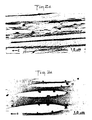
- Fig. 2d is a bright field transmission electron micrograph, obtained on a transmission electron microscope (TEM), of a HMW PB-1/Zn MOC film according to the present invention made from a solution with a 30 wt.% zinc compound loading;
- Fig. 3 is a diagrammatic representation of the morphology of pure HDPE when a strain is applied in the direction of the arrow and shows the crystalline lamellae and adjacent amorphous regions of the polymer;
- Fig. 3a graphically represents the disposition of a globule of MOC solution as the discontinuous phase in an emulsion having a continuous phase constituted by a solution of HDPE;
- Fig. 3b graphically represents the transformation of the MOC solution globule in the emulsion of Fig. 3a into a roughly spherical polycrystalline aggregate within the HDPE lamellae constituting the thin oriented polymer film formed during the application of a strain to the HDPE/MOC emulsion in the direction of the arrow;
- Fig. 3c is an enlarged graphic representation of one of the polymer lamellae shown in the circled area of Fig. 3b and illustrates the growth of the polymer macromolecules in the direction of the strain and the lamellar growth of the polymer in directions perpendicular to the direction of the strain;
- Figs. 3d, 3e and 3f are bright field TEM micrographs of HDPE/Zn MOC films according to the present invention made from solutions with, respectively, 10%, 30% and 60% by weight zinc compound loadings;
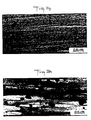
- Figs. 3g and 3h are bright field TEM micrographs of, respectively, HMW PB-1 and HDPE films according to the present invention made from solutions with 30 wt.% aluminum compound loadings;
- Figs. 3i and 3j are bright field TEM micrographs of, respectively, HMW PB-1 and HDPE films according to the present invention made from solutions with 30 wt.% silver compound loadings;
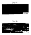
- Figs. 3k and 3m are bright field TEM micrographs of, respectively, HMW PB-1 and HDPE films according to the present invention made from solutions with 20 wt.% copper compound loadings;
- Fig. 3n is a phase contrast TEM micrograph of a thin HMW PB-1/Fe MOC film prepared without the application of a magnetic field during cooling; and
- Figs. 3p and 3q are bright field TEM micrographs of two films of the same composition as the film represented by Fig. 3n but prepared one with an application of a magnetic field parallel to the plane of the supporting surface during cooling and the other with an application of a magnetic field perpendicular to the plane of the supporting surface during cooling.
- The principles of the present invention will, we believe, be best comprehended from the following description of representative film-forming procedures using HMW PB-1 and HDPE as the polymers, the compounds listed in Table I as the MOCs, and xylene as the common solvent for the polymers and the MOCs.
- Referring now to the drawings in greater detail, Fig. 2 illustrates graphically a single needle crystal of pure HMW PB-1 formed by the unidirectionally extended polymer macromolecules of a film thereof when the same is oriented by being subjected to a strain in the direction of the arrow A. Correspondingly, Fig. 3 illustrates graphically the partly crystalline and partly amorphous structure of an oriented film of pure HDPE formed when the same is subjected to a strain in the direction of the arrow B, showing the unidirectional extension of the polymer macromolecules in the direction of the applied strain as well as the lamellar growth (a chain folding within the lamellae) of the polymer bidirectionally in all directions of the arrow C in a plane perpendicular to the direction of the applied strain. In this context, it should be understood, the designation of the polymers as "pure" is intended only to indicate that they are free of MOCs and other comparable substances, not necessarily that they are chemically pure.
- Three solutions of HMW PB-1 in xylene and three solutions of HDPE in xylene were prepared, each solution being maintained at a temperature of 140°C and containing 0.4% by weight of the respective polymer. Thereafter, three different quantities of the Zn MOC set forth in Table I were added on the one hand to the three HMW PB-1 solutions and on the other hand to the three HDPE solutions, such that the respective amounts of the MOC solution in each type of solution were the equivalents of 10%, 30% and 60% by weight of the MOC in a solid MOC-polymer mixture. The Zn MOC being itself also soluble in xylene, the resulting solutions were emulsions of globules of the MOC solution dispersed in the various polymer solutions, as is graphically illustrated in Fig. 2a for the HMW PB-1/MOC solution and in Fig. 3a for the HDPE/MOC solution.
- The various solutions were then formed into respective films by means of a
system 10 such as is illustrated schematically in Fig. 1 and basically includes aglass plate 11 defining a supporting surface, means (not shown) for heating the supporting surface, and a take-up roll 12, the procedure essentially following the method developed by Petermann and Gohil¹¹. Thus, in each case a few milliliters of the respective emulsion were deposited onto a clean glass plate so as to form thereon athin film 13. The plate was maintained at the solution temperature (140°C), and a portion of the xylene was permitted to evaporate from the film during an interval of a few (e.g., 3-5) seconds. The evaporated portion of the xylene was primarily constituted by the solvent of the polymer solution, because the rate of evaporation from the continuous phase of the emulsion is higher than the rate of evaporation from the discontinuous phase due to the fact that the globules of MOC solution are surrounded by the polymer solution. - At the end of the preliminary drying interval, i.e., after about 5 seconds, the somewhat tacky
thin film 13 on theplate 11 was contacted by thetakeup roll 12 and the latter, with an end region of the film adhering thereto, was picked up and displaced away from the plate in the direction of the arrow D at a rate of a few (approximately 1-6) cm/sec to exert a strain on the film. During the drawing operation, the remaining xylene present in the picked upfilm 13a evaporated and a dried and solid, highly oriented film about 80 nm (800 Å) thick was obtained which could be wound up on the take-up roll 12 without risk of adhesion between the turns of the film. - By virtue of the extreme thinness of these films, resulting from their production by the method of the present invention, they were electron transparent. It was possible, therefore, to study them with a transmission electron microscope (TEM). For this purpose, a Philips EM 430 T transmission electron microscope was used (which was operated at 200 kV in order to minimize beam damage to the samples). In conjunction therewith, energy dispersive x-ray analysis (EDAX) was performed with a Philips EDAX PV 9900 system (using the STEM attachment therefor in point mode in order to permit selection and examination of small areas on the samples).
- Based on these studies, it appears that the HMW PB-1/Zn MOC films have essentially the same structure and morphology as the pure HMW PB-1 films represented by Fig. 2 but differ therefrom in that they contain within them (see Fig. 2c) fibers of various lengths of the zinc compound. The TEM micrograph of such a film made from a solution with a loading of 30% by weight of the zinc compound (Fig. 2d) shows that the MOC fibers are aligned in the direction of the needle crystals of the HMW PB-1, which is also the direction of drawing designated by the arrow E, i.e., the orientation direction, and that the packing density of the crystallites (single-crystal grains) within the MOC (the selected area electron diffraction pattern of the fibers, which is not shown, indicates that the fibers are polycrystalline regions) decreases in the pull direction. The observations of comparable TEM micrographs of thin oriented HMW PB-1/Zn MOC films with the mentioned higher and lower zinc compound loadings do not lead to any different conclusions.
- In this connection it should be pointed out that a possible explanation of the above-described morphology of the HMW PB-1/Zn MOC films may be the following. As previously mentioned, when the filmforming emulsion consisting of the discontinuous phase of finite globules of the MOC solution dispersed in the continuous phase of the polymer solution is deposited onto the hot glass plate, most of the xylene evaporates from the continuous phase within 3 to 4 seconds while evaporation from the globules is slower due to the continuous phase surrounding the globules of the MOC solution. Seed crystals can then form in the globules of the MOC solution either before or after the drawing of the film starts, and they can act as nuclei for further crystallization. Evaporation of the xylene from the globules proceeds much faster during drawing than before and is completed at the end of the drawing process when the fibers of solid MOC are formed in the polymer film.
- In the case of HMW PB-1, the polymer macromolecules are extended during pulling and start to form needle crystals during film formation. These molecules, which before the start of the drawing process are crosslinked with the zinc compound at the interface between the polymer and each MOC globule (see Fig. 2a), exert a force on the globules in the pull direction, i.e., the direction of the arrow F. Thus, the globules become elongated (see Fig. 2b). During this process, growth of zinc diethyldithiocarbamate crystals takes place, starting from the previously formed seed crystals. This results in the observed polycrystalline metal fibers which show good wettability with and hence excellent adhesion to the surrounding polymer.
- In the case of HDPE, on the other hand, the TEM micrographs (Figs. 3d, 3e and 3f), in each of which the pull direction is indicated by the arrow G, show definite differences in the film structure depending on the degree of Zn MOC loading in the original solution. Thus, at a low (10 wt.%) loading of the zinc compound, primarily single zinc diethyldithiocarbamate crystals are formed which become embedded in the polyethylene; the well-defined shape of the individual crystals (see Fig. 3d) reflects their single-crystalline character. An increase of the Zn MOC content of the solution to 30 wt.%, by way of contrast, leads more generally to the formation of roughly spherical clusters of zinc compound crystals each consisting of several crystallites which are attached to each other (see Fig. 3e); the cluster sizes, which in some instances are barely differentiable from the crystal sizes seen in Fig. 3d, range between about 0.2 µm and 1.0 µm. When the zinc compound loading in the solution reaches 60 wt.%, however (see Fig. 3f), a marked increase in cluster size, ranging between about 0.7 µm and 3.6 µm, is detected, although the cluster density (the number of clusters per unit area) has not changed significantly between Figs. 3e and 3f. In addition, whereas the aggregates in all three HDPE films are roughly spherical, in the film of Fig. 3f the aggregates, by virtue of their size, are much more spherical than in the films of Figs. 3d and 3e, and the associated diffraction patterns (not shown) indicate that the aggregates are clearly polycrystalline.
- The fact that in the HDPE/Zn MOC films the zinc compound forms roughly spherical generally polycrystalline aggregates in the solid film after drawing indicates that the MOC solution globules (see Fig. 3a) in the starting emulsion remain unaltered in shape during crystallization (see Fig. 3b) when a strain is applied to the film in the direction of the arrow H. From this we conclude that the polyethylene molecules exert no force on the MOC globules during the drawing process. A reason for this might be the lamellar growth of this polymer during crystallization. Though the polymer macromolecules grow in the direction of the strain, the lamellae within the film (see also Fig. 3c) grow bidirectionally in all directions in a plane perpendicular to the pull direction, and thus no resultant force acts on the globules to deform them.
- Three solutions of HMW PB-1 in xylene and three solutions of HDPE in xylene were prepared as in Example 1, each solution being maintained at a temperature of 140°C and containing 0.4% by weight of the respective polymer. Thereafter, sufficient quantities of the Al, Ag and Cu MOCs set forth in Table I were added to the respective polymer solutions to obtain resulting solutions, in the form of emulsions of globules of the various MOC solutions dispersed in the various polymer solutions (see Figs. 2a and 3a), having the polymer/MOC compositions and the MOC weight fractions set forth in Table II.
TABLE II MOC weight Polymer MOC (wt.%) HMW PB-1 Aluminum (2)ethylhexanoate 30 HDPE Aluminum (2)ethylhexanoate 30 HMW PB-1 Silver cyclohexanebutyrate 30 HDPE Silver cyclohexanebutyrate 30 HMW PB-1 Copper cyclohexanebutyrate 20 HDPE Copper cyclohexanebutyrate 20 - The various emulsions were then formed into respective thin oriented films by means of the same system (see Fig. 1) and procedure as described in Example 1 above, and were likewise studied with the aid of the Philips EM 430 T transmission electron microscope and the Philips EDAX PV 9900 energy dispersive x-ray analysis system.
- TEM micrographs of oriented HMW PB-1 and HDPE films containing the aluminum compound are shown in Figs. 3g and 3h, respectively. In the case of the HMW PB-1 film, numerous small dark domains representing aluminum compound can be seen in Fig. 3g along with the oriented needle crystals of the polymer, with the aluminum domains being generally somewhat inclined in the direction of the polymer orientation. In the case of the HDPE film, Fig. 3h shows, among the polyethylene lamellae, a number of dark domains of roughly spherical configuration which vary considerably in size.
- The TEM micrographs of silver compound-loaded HMW PB-1 and HDPE films are shown in Figs. 3i and 3j, respectively. From Fig. 3i it is evident that the Ag MOC is oriented in the orientation direction of the film, i.e., the direction of the polymer needle crystals. The metal fibers are roughly 1-2 µm long and 0.4 µm wide. Upon high magnification, numerous single particles, oriented along the orientation direction, are visible, although some of these particles seem to have coalesced from smaller ones into somewhat larger aggregates during the film formation. The presence of silver in these regions was confirmed by EDAX. Fig. 3j shows, in the morphology of an oriented HDPE film, the presence of numerous small roughly spherical domains as well as large flakelike areas, which were identified (by EDAX) as silver-rich regions. In addition to the reflections of the HDPE, the diffraction pattern (not shown) indicates the presence of some weak spots resulting from the silver compound particles, and this indicates a certain degree of crystalline order.
- The TEM micrographs of Figs. 3k and 3m show the morphologies of oriented HMW PB-1 and HDPE films containing the copper compound. Both morphologies reveal the presence of slightly deformed spherical domains with their long axes being aligned in the direction of film orientation, which is also the polymer chain direction. In the case of the HMW PB-1 films, very thin metal-organic compound fibers (about 20 nm in diameter and several microns long) were also observed, the fibers being precisely aligned in the orientation direction.
- We conclude from the results of Example 2 that in the oriented thin polymer/MOC films, which like those described in Example 1 were drawn from a common solution of both components and subjected to a strain, the arrangement of the MOC in the films is strongly affected by the morphology of the polymer macromolecules. While in the case of oriented lamellar HDPE, no pronounced orientation of the MOC was observed, in the case of needle crystalline HMW PB-1, a preferred orientation of the MOC in the films was detected. Also, diffraction patterns show that some crystalline order exists in the metal-organic compound. It might also be concluded from the results that reactive sidegroups of the polymer molecules act as crosslinking sites¹⁰ for the organic part of the MOC. This would explain the observed interaction between the polymer morphology and the MOC arrangement in the case of HMW PB-1, with its C₂H₅ sidegroups.
- It should be noted here that oriented filmforming procedures essentially identical with those described in Examples 1 and 2 have also been performed utilizing the Fe and Co MOCs set forth in Table I. The results were comparable to those achieved with the indicated Zn, Al, Ag and Cu MOCs. We conclude from this that making very thin oriented polymer/MOC films according to the present invention by application of a physical strain or pull to a film derived from a common solution of the polymer and the MOC is feasible irrespective of whether the metal component of the MOC is a magnetic or a nonmagnetic element.
- A solution of HMW PB-1 in xylene was prepared, the solution being maintained at a temperature of 140°C and containing 0.1% by weight of the polymer. Thereafter, a sufficient quantity of the Fe MOC set forth in Table I was added to the polymer solution to obtain a resulting solution, in the form of an emulsion of globules of the Fe MOC solution dispersed in the polymer solution (see Fig. 2a), in which the iron compound was 30% by weight of the total solids dissolved.
- Three thin films of the emulsion were then formed on respective supporting surfaces (in this case each constituted by a carbon-coated TEM copper grid) which were held at a constant temperature of 140°C. Slow cooling of the films to room temperature was permitted to take place at a cooling rate of 0.5°C/min, with one of the films being subjected, during the cooling process, to a 4.0 kGauss magnetic field applied parallel to the plane of the grid, a second one of the films being subjected, during the cooling process, to a 8.2 kGauss magnetic field applied perpendicular to the plane of the grid, and the third film being permitted to cool without being subjected to a magnetic field.
- As in Examples 1 and 2, the films were then studied with the aid of the Philips EM 430 T transmission electron microscope and the Philips EDAX PV 9900 energy dispersive x-ray analysis system.
- With respect to the film cooled in the absence of a magnetic field, the TEM micrograph of Fig. 3n shows that the HMW PB-1 formed irregular dendritic crystals which grew in two directions perpendicular to each other. (Dendritic growth of polymers has been extensively investigated and it is commonly acknowledged that the creation of new fold planes during crystal growth leads to the appearance of dendrites.¹²) Circular domains were observed within the polymer film which were identified (by EDAX) as iron-rich regions. The iron-rich domains within the polymer film were, however, found to concentrate at the edges of the TEM grid bars instead of being spread uniformly throughout the film.
- The influence of a magnetic field applied parallel to the plane of the substrate during cooling is shown in the TEM micrograph of Fig. 3p. Dendrites were no longer present, but rather a homogeneous film with alignment of boundaries parallel to each other was seen. Again there were circular domains which were identified (by EDAX) as iron-rich regions, but in this case they were homogeneously distributed over the entire area. This result is believed to be due to the fact that the applied magnetic field engenders a movement of the iron-rich regions in the plane of the film during the crystallization stage. Orientation of the film can be seen from the micrograph. Texturing was confirmed from electron diffraction patterns.
- As shown in the TEM micrograph of Fig. 3q, a difference is observed in the structure of the film when the magnetic field is applied perpendicular to the plane of the grid. The direction of the magnetic field in this case is such, that it effectively pins iron-rich regions in place relative to the substrate upon the solution being deposited onto the grid and prevents their movement in the plane of the substrate during cooling and film formation. The spherical regions seen in Fig. 3q contain several domains of iron-rich material. This, and the fact that these regions are larger than the individual domains seen earlier, suggests that coalescence of iron-rich domains within the polymer takes place during solidification along with a uniform distribution of the larger regions throughout the plane of the film. Electron diffraction confirmed once again that the film was textured.
- It can be extrapolated from the foregoing description of the HMW PB-1/Fe MOC film morphology that similar results will obtain in films formed with other MOCs the metal component of which is a magnetic element, e.g., with the Co MOC and the Ni MOC set forth in Table I.
- Films according to the present invention are suited for use as dielectrics in capacitors, with the presence of a greater or lesser MOC loading providing the dielectric with an appropriately modified dielectric constant. Such films appear further useful as shielding materials for sensitive devices such as integrated circuits to protect the same against exterior electromagnetic interference. Films where the metal component of the MOC is magnetic, especially iron, may also find use in such applications as magnetic memory devices, electromagnetic wavelength selectors, and the like. It will also be understood that a very thin oriented film according to the present invention can be laid over itself, e.g., by being wound or folded, so as to form a final film of a much greater thickness, e.g., 0.5 mm.
-
- 1. "Metal-Containing Polymer Systems", edited by J.E. Sheats et al., Plenum Press, New York (1985)
- 2. H.W. Leonhardt et al., Plaste Kautschuk, 31, 192 (1984)
- 3. G. Lecayon et al., Scanning Microscopy, 1(1), 85 (1987)
- 4. H.G. Tompkins, Thin Solid Films, 119, 337 (1984)
- 5. B.M. Dekoven and P.C. Hagans, Applied Surf. Sci., 27(2), 199 (1986)
- 6. H. Biedermann, Vacuum, 34, 405 (1984)
- 7. D.L. Allara et al., J. Polym. Sci.: Chem. Ed., 14, 93 (1976)
- 8. M. Pineri et al., J. Polym. Sci.: Phys. Ed., 13, 1881 (1975)
- 9. C.T. Meyer et al., Polymer, 17, 382 (1976)
- 10. J.M.G. Cowie and N.M.A. Wadi, Polymer, 26, 1566 (1985)
- 11. J. Petermann and R.M. Gohil, J. Mat. Sci., 14, 2260 (1979)
- 12. P.H. Geil, Polymer Single Crystals, Interscience Publishers, New York (1963)
Claims (20)
Applications Claiming Priority (2)
| Application Number | Priority Date | Filing Date | Title |
|---|---|---|---|
| US07/291,546 US4963429A (en) | 1988-12-29 | 1988-12-29 | Thin oriented polymer films containing metal-organic compounds |
| US291546 | 1988-12-29 |
Publications (2)
| Publication Number | Publication Date |
|---|---|
| EP0376536A2 true EP0376536A2 (en) | 1990-07-04 |
| EP0376536A3 EP0376536A3 (en) | 1992-03-11 |
Family
ID=23120748
Family Applications (1)
| Application Number | Title | Priority Date | Filing Date |
|---|---|---|---|
| EP19890312934 Withdrawn EP0376536A3 (en) | 1988-12-29 | 1989-12-12 | Thin oriented polymer films containing metal-organic compounds, and methods of making the same |
Country Status (2)
| Country | Link |
|---|---|
| US (1) | US4963429A (en) |
| EP (1) | EP0376536A3 (en) |
Families Citing this family (12)
| Publication number | Priority date | Publication date | Assignee | Title |
|---|---|---|---|---|
| US5409782A (en) * | 1988-05-02 | 1995-04-25 | Orient Watch Company | Composite film |
| MXPA05008220A (en) * | 2003-01-31 | 2005-10-05 | M & G Polimeri Italia Spa | Oxygen-scavenging articles devoid of visual spots upon oxidation and a method of their preparation. |
| US9011627B2 (en) * | 2007-10-05 | 2015-04-21 | Carver Scientific, Inc. | Method of manufacturing high permittivity low leakage capacitor and energy storing device |
| WO2009046341A1 (en) | 2007-10-05 | 2009-04-09 | David Carver | High permittivity low leakage capacitor and energy storing device and method for forming the same |
| US8940850B2 (en) | 2012-08-30 | 2015-01-27 | Carver Scientific, Inc. | Energy storage device |
| KR20120037464A (en) * | 2009-06-12 | 2012-04-19 | 로오드 코포레이션 | Method for shielding a substrate from electromagnetic interference |
| US10199165B2 (en) | 2012-08-30 | 2019-02-05 | Carver Scientific, Inc. | Energy storage device |
| US9805869B2 (en) | 2012-11-07 | 2017-10-31 | Carver Scientific, Inc. | High energy density electrostatic capacitor |
| BR112015012259A2 (en) * | 2012-11-28 | 2017-07-11 | Dow Global Technologies Llc | microclayer component, method for producing a microclayer component, film and article |
| US20140295101A1 (en) * | 2013-03-29 | 2014-10-02 | Carver Scientific, Inc. | High permittivity low leakage capacitor and energy storing device |
| CN108292514B (en) | 2015-11-06 | 2022-04-29 | 卡弗科学有限公司 | Electric entropy memory device |
| CN110431647B (en) | 2016-12-02 | 2022-06-28 | 卡弗科学有限公司 | Storage Devices and Capacitive Energy Storage Devices |
Family Cites Families (10)
| Publication number | Priority date | Publication date | Assignee | Title |
|---|---|---|---|---|
| US4027366A (en) * | 1973-08-02 | 1977-06-07 | Beatrice Foods Co. | Multilayer coated substrate |
| US3991130A (en) * | 1973-10-10 | 1976-11-09 | Ciba-Geigy Corporation | Organo-nickel salts as adhesion promotors for vulcanizable elastomers to metals |
| US3905947A (en) * | 1973-10-10 | 1975-09-16 | Ciba Geigy Corp | Organo-nickel salts as adhesion promotors for vulcanizable elastomers to metals |
| US4221697A (en) * | 1974-05-29 | 1980-09-09 | Imperial Chemical Industries Limited | Composite materials |
| US4243460A (en) * | 1978-08-15 | 1981-01-06 | Lundy Electronics & Systems, Inc. | Conductive laminate and method of producing the same |
| US4243710A (en) * | 1978-12-06 | 1981-01-06 | Ferro Corporation | Thermoplastic electrode ink for the manufacture of ceramic multi-layer capacitor |
| DE3601518A1 (en) * | 1985-01-18 | 1986-07-24 | Toagosei Chemical Industrial Co., Ltd., Tokio/Tokyo | PRIMER |
| IT1190366B (en) * | 1985-06-19 | 1988-02-16 | Bozetto Ind Chim | STABILIZED POLYMERIC COMPOSITIONS AND STABILIZING SYSTEMS SUITABLE FOR THE PURPOSE |
| JPS62170568A (en) * | 1986-01-17 | 1987-07-27 | 株式会社豊田自動織機製作所 | Apparatus for producing oriented fiber aggregate |
| US4728554A (en) * | 1986-05-05 | 1988-03-01 | Hoechst Celanese Corporation | Fiber structure and method for obtaining tuned response to high frequency electromagnetic radiation |
-
1988
- 1988-12-29 US US07/291,546 patent/US4963429A/en not_active Expired - Fee Related
-
1989
- 1989-12-12 EP EP19890312934 patent/EP0376536A3/en not_active Withdrawn
Also Published As
| Publication number | Publication date |
|---|---|
| EP0376536A3 (en) | 1992-03-11 |
| US4963429A (en) | 1990-10-16 |
Similar Documents
| Publication | Publication Date | Title |
|---|---|---|
| EP0376536A2 (en) | Thin oriented polymer films containing metal-organic compounds, and methods of making the same | |
| Ren et al. | Size-related ferroelectric-domain-structure transition in a polycrystalline PbTiO 3 thin film | |
| DE1483246C3 (en) | Process for the production of an amorphous alloy layer | |
| DE60214083T2 (en) | Production method for magnetic metal powder and magnetic metal powder | |
| Shindo et al. | Internal structure analysis of monodispersed peanut-type hematite particles produced by the gel-sol method | |
| Cohen | Anomalous magnetic films | |
| Hur et al. | Effect of annealing on magnetic properties and microstructure of electroless nickel-copper-phosphorus alloy deposits | |
| DE69527148T2 (en) | AROMATIC POLYAMIDE FILM, METHOD FOR THE PRODUCTION THEREOF AND MAGNETIC RECORDING PRODUCTS MADE THEREOF AND SOLAR CELL | |
| DE69027684T2 (en) | MAGNETIC MATERIALS AND PRODUCTS MADE THEREOF | |
| CH676893A5 (en) | ||
| DE69723503T2 (en) | Ultrafine particle, process for its production, production of moldings from these particles and fullerenes and their production process | |
| DE69224956T2 (en) | Film made of "cluster" type carbon with electrical conductivity and process for its production | |
| DE69416906T2 (en) | Process for producing a material from metal oxide mixtures | |
| Rybnikář | Interactions in the system isotactic polypropylene–calcite | |
| EP0172566B1 (en) | Perpendicular magnetic recording medium and production process thereof | |
| JP7478481B2 (en) | Nickel nanowires and their manufacturing method | |
| DE4203208A1 (en) | COATING AGENTS FOR PLASTIC FILMS | |
| Shahid et al. | Morphologies of silver nanoparticles (Ag NPs) synthesized by hydrothermal and laser ablation techniques | |
| Singh et al. | Electron microscopy of nucleation and growth of indium and tin films | |
| DE69209863T2 (en) | Biaxial stretch oriented polyester film for capacitor dielectric | |
| JP2000001706A (en) | High crystalline silver particles, method for producing the same, and conductive paste comprising high crystalline silver particles | |
| Welland et al. | Single crystals of V amylose | |
| DE3786362T2 (en) | Substrates coated with dissolved metal particle aggregates. | |
| Fuchs et al. | Crystallization of thin antimony deposits on amorphous carbon | |
| JP2623421B2 (en) | Method for producing polymer composite in which fine particles of metal sulfide are dispersed |
Legal Events
| Date | Code | Title | Description |
|---|---|---|---|
| PUAI | Public reference made under article 153(3) epc to a published international application that has entered the european phase |
Free format text: ORIGINAL CODE: 0009012 |
|
| AK | Designated contracting states |
Kind code of ref document: A2 Designated state(s): BE CH DE GB LI NL |
|
| PUAL | Search report despatched |
Free format text: ORIGINAL CODE: 0009013 |
|
| AK | Designated contracting states |
Kind code of ref document: A3 Designated state(s): BE CH DE GB LI NL |
|
| 17P | Request for examination filed |
Effective date: 19920826 |
|
| 17Q | First examination report despatched |
Effective date: 19940418 |
|
| STAA | Information on the status of an ep patent application or granted ep patent |
Free format text: STATUS: THE APPLICATION IS DEEMED TO BE WITHDRAWN |
|
| 18D | Application deemed to be withdrawn |
Effective date: 19941029 |