EP0376569A2 - Bandkassettenspule mit durch ein dichromatisches Giessverfahren geformtem Oberteil - Google Patents
Bandkassettenspule mit durch ein dichromatisches Giessverfahren geformtem Oberteil Download PDFInfo
- Publication number
- EP0376569A2 EP0376569A2 EP89313211A EP89313211A EP0376569A2 EP 0376569 A2 EP0376569 A2 EP 0376569A2 EP 89313211 A EP89313211 A EP 89313211A EP 89313211 A EP89313211 A EP 89313211A EP 0376569 A2 EP0376569 A2 EP 0376569A2
- Authority
- EP
- European Patent Office
- Prior art keywords
- flange portion
- reel
- tape cassette
- outer peripheral
- hub
- Prior art date
- Legal status (The legal status is an assumption and is not a legal conclusion. Google has not performed a legal analysis and makes no representation as to the accuracy of the status listed.)
- Granted
Links
Images


Classifications
-
- G—PHYSICS
- G11—INFORMATION STORAGE
- G11B—INFORMATION STORAGE BASED ON RELATIVE MOVEMENT BETWEEN RECORD CARRIER AND TRANSDUCER
- G11B23/00—Record carriers not specific to the method of recording or reproducing; Accessories, e.g. containers, specially adapted for co-operation with the recording or reproducing apparatus ; Intermediate mediums; Apparatus or processes specially adapted for their manufacture
- G11B23/02—Containers; Storing means both adapted to cooperate with the recording or reproducing means
- G11B23/04—Magazines; Cassettes for webs or filaments
- G11B23/08—Magazines; Cassettes for webs or filaments for housing webs or filaments having two distinct ends
- G11B23/087—Magazines; Cassettes for webs or filaments for housing webs or filaments having two distinct ends using two different reels or cores
- G11B23/08707—Details
- G11B23/08728—Reels or cores; positioning of the reels in the cassette
-
- G—PHYSICS
- G11—INFORMATION STORAGE
- G11B—INFORMATION STORAGE BASED ON RELATIVE MOVEMENT BETWEEN RECORD CARRIER AND TRANSDUCER
- G11B23/00—Record carriers not specific to the method of recording or reproducing; Accessories, e.g. containers, specially adapted for co-operation with the recording or reproducing apparatus ; Intermediate mediums; Apparatus or processes specially adapted for their manufacture
- G11B23/02—Containers; Storing means both adapted to cooperate with the recording or reproducing means
- G11B23/037—Single reels or spools
Definitions
- the present invention relates generally to tape cassette reels and more particularly to a tape cassette reel having wound therearound a magnetic tape and which is incorporated in a video tape cassette.
- a tape cassette reel TR is comprised of a reel hub 1 formed as one body with a lower flange portion 2 and an upper flange portion 5 secured to the upper end face of the reel hub 1.
- the upper flange portion 5 is comprised of a central portion 3 made of an opaque material of a desired color and an outer peripheral flange portion 4 made of a transparent, synthetic resin such as acrylonitrile butadiene styrene copolymer (ABS) resin, so-called SAN resin and the like according to the so-called dichromatic molding method.
- ABS acrylonitrile butadiene styrene copolymer
- the outer surface of the colored central portion 3 of the upper flange portion 5 is made lower, as viewed in the figure, than the outer peripheral flange portion 4 by a very small amount.
- An aperture 6 is formed through the central portion 3 of the flange portion 5 at its central portion, and a center pin 7 is loosely supported between the central, lower surface 3 of the upper flange portion 5 and the central, upper end face of the reel hub 1.
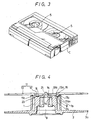
- the center pin 7 which comes in contact with cassette reel pushing springs S provided in a cassette housing C shown in Fig. 3.
- a pouring gate g upon molding is formed between the aperture 6 and the outer peripheral flange portion 4.
- Protruding portions 4a, 4a are formed on the inner peripheral side of the transparent, outer peripheral flange portion 4 of the upper flange portion 5 so as to protrude in the radially central direction of the colored central portion 3.
- Two pouring gates g are also formed on the outer surfaces of these protruding portions 4a, 4a, and these pouring gates g are used in the molding-process for molding the transparent, outer peripheral flange portion 4.
- a hub drive shaft engaging aperture 9 is formed on the lower surface side of the reel hub 1 so that it can be engaged with a hub drive shaft of a video tape recorder body (not shown).
- a clamp piece engaging portion 8 is formed around the peripheral surface of the reel hub 1. The clamp piece engaging portion 8 is used to fix the end of a video tape (not shown) thereto together with a clamp piece (not shown).
- Reel brake engaging teeth 2a are formed around the outer peripheral surface of the lower flange portion 2. Then, the upper flange portion 5 is welded at the lower surface of the colored central portion 3 thereof to the upper end face of the reel hub 1 by an ultrasonic welding-process, thereby completing the tape cassette reel.
- the protruding portions are formed on the inner peripheral side of the outer peripheral flange portion so as to protrude toward the inside of the colored central portion, and the pouring gates are formed on the outer surfaces of the protruding portions.
- the marks of the pouring gates remain on the outer surfaces of the protruding portions of the outer peripheral flange portion which is protrusively molded with the colored central portion, deteriorating the quality of the external appearance of the tape cassette reel. If the tape cassette reel is very small, just like a tape cassette reel for a tape cassette of 8 mm video tape recorder, the marks of the pouring gates become very conspicuous so that the users feel as if they had bought an inferior product.
- a tape cassette reel comprising:
- the tape cassette reel of the invention is for use in a video tape cassette similarly to the example of the prior art shown in Fig. 1.
- like parts corresponding to those of Figs. 1 to 3 are marked with the same references and therefore need not be described in detail.
- the lower flange portion 2 is formed as one body with the reel hub 1, and an upper flange 11 is bonded to the upper end face 1a of the reel hub 1.
- the reel hub 1 is made of a synthetic resin of a light color such as white and so on.
- the upper flange portion 11 is comprised of a central portion 12 made of an opaque, synthetic resin of a desired color such as black, and an outer peripheral flange portion 13 made of a transparent resin by the dichromatic molding-process.
- the peripheral portion 13 has substantially the same diameter as the lower flange portion 2.
- the central portion 12 of the upper flange portion 11 has a diameter smaller than that of the reel hub 1 by a very small amount, and the upper surface side of the central portion 12 is concaved except for its peripheral edge portion to provide a concaved surface 12a.
- An aperture 14 is formed through the central portion of the concaved surface 12a.
- a plurality of through-holes for example, six large and small through-holes 15a and 15b, respectively, are alternately formed through the concaved surface 12a and around the aperture 14 with predetermined spacings, and a step 16 is formed on the radially inner surface of the peripheral side surface of the central portion 12.
- the pouring gate g for the central portion 12 is formed on its surface which faces the hub 1 so as to mold the central portion 12.
- a plurality of shock-absorbing rib portions 17, for example, four shock-absorbing rib portions 17a, 17b, 17c and 17d, having a predetermined spacing therebetween, are formed on the lower side, as viewed in Figure 4, of the inner peripheral edge 13a of the lower flange portion 13.
- the shock absorbing rib portions 17a, 17b, 17c, and 17d are radially exterior of the central hub 1 but radially interior of an outer cylindrical hub extension 1b that is coaxial with the hub 1.
- the radially inner peripheral edge 13a of the outer flange portion 13 is bonded to the central portion 12, and these shock-absorbing rib portions 17a, 17b, 17c and 17d are outwardly meshed with the step 16 formed around the peripheral side surface of the central portion 12.
- the rib portion 17a is inwardly elongated to form an elongated portion 17 a1
- the pouring gate g is formed on the lower surface side of the elongated portion 17 a1 , as viewed in Figure 4, to be between the radially outer surface of the hub 1 and the radially inner surface of the hub extension 1b.
- the thus constructed central portion 12 and the thus constructed outer peripheral flange portion 13 are integrally molded as one body by the dichromatic molding method as described previously.
- the peripheral side surface of the central portion 12 and the inner peripheral edge 13a of the outer peripheral flange portion 13 are integrally molded as one body and the step 16 and the rib portions 17a, 17b, 17c and 17d are integrally molded as one body, thereby forming the upper flange portion 11.
- a protrusion 21 is integrally formed in the reel hub 1 at the central portion of the upper end face 1a, and this protrusion 21 corresponds to the center pin 7 of the prior-art example.
- Large and small protrusions 22a, 22b, respectively, are formed on the upper and face 1a around the protrusion 21 so as to correspond to the through-holes 15a, 15b formed through the central portion 12 of the upper flange portion 11.
- a concaved portion 23 is formed on the upper end face 1a of the reel hub 1, and this concaved portion 23 accommodates the pouring gate g of the central portion 12 of the upper flange portion 11. Further, a notch 24 is formed in the peripheral edge of the upper end face 1a, and this notch 24 opposes the elongated portion 17 a1 of the shock-absorbing rib portion 17a of the outer peripheral flange portion 13.
- the bonding of the upper flange portion 11 on the upper end face 1a of the thus arranged reel hub 1 will now be described.
- the protrusions 22 are inserted into the through-holes 15. That is, the large protrusions 22a are inserted into and engaged with the large apertures 15a, and the small protrusions 22b are inserted into and engaged with the small apertures 15b.
- the top of the protrusion 21 of the reel hub 1 protrudes upwards from the central aperture 14 of the central portion, and the pouring gate g, i.e.
- the pouring gate mark of the central portion 12 is opposed to the concaved portion 23 of the reel hub 1. Also, the elongated portion 17 a1 of the shock-absorbing rib portion 17a of the outer peripheral flange portion 13 and the pouring gate g, i.e. the pouring gate mark, are opposed to and inserted into the concaved portion 24.
- the inner surface of the central portion 12 can be stably ultrasonically bonded to the upper end face 1a of the reel hub 1 without wobble.
- the small protrusions 22b protruding from the small apertures 15b of the central portion 12 are welded at the tops thereof and caulked, thereby securing the upper flange portion 11 to the reel hub 1.
- the diameter of a caulking portion 22 b1 of the small protrusion 22b is selected to be the same as that of the large protrusion 22a protruding upward from the large aperture 15a.
- the pouring gate g used to mold the outer peripheral flange portion 13 is provided on the inner surface edge portion so that during molding the resin smoothly flows and spreads to the outer periphery side, thereby positively molding the outer peripheral flange portion 13 of the upper flange portion 11. Further, the pouring gate mark is located at the inner surface side of the elongated portion 17 a1 of the shock-absorbing rib portion 17 and is hidden by the opaque central portion 12. Therefore, the pouring gate mark of the outer peripheral flange portion 13 can not be seen from the outer surface side and the external appearance of the tape cassette reel of the invention can be improved in quality.
- the shock-absorbing rib portions 17 are held between the central portion 12 and the upper end face 1a of the reel hub 1 with pressure so that, even when the outer peripheral flange portion 13 is shocked considerably, the outer peripheral flange portion 13 can be prevented from being disengaged from the reel hub 1. In other words, the upper flange portion 11 can be prevented from being damaged.
- the pouring gate mark of the central portion 12 is located on its inner surface side, the pouring gate mark of the central portion 12 is also hidden by the opaque central portion 12 and can not be seen from the outside, thereby further improving the external appearance of the tape cassette reel in quality.
- the color of the central portion of the upper flange portion is not limited to black and can be changed to various colors such as silver and the like in accordance with the design of the video tape cassette. Furthermore, the positions at which the shock-absorbing rib portions are provided on the outer peripheral flange portion and the positions at which the pouring gates are formed can be changed freely.
- the upper flange portion can be efficiently molded, whereby the tape cassette reel can be manufactured at high efficiency. Further, the pouring gate marks for the upper flange portion are completely hidden from the outside, which fact can increase the external appearance of the tape cassette reel in quality.
- the pouring gate mark of the upper flange portion is completely hidden from the outside, and the concaved portion corresponding to the pouring gate mark of the upper flange portion is formed on the surface of the upper flange portion which is secured to the reel hub.
- the pouring gate mark is inserted into the concaved portion, whereby the upper flange portion can be stably secured to the upper end face of the reel hub without wobble. Therefore, it is possible to provide a tape cassette reel whose external appearance is excellent and whose quality is excellent.
Landscapes
- Storage Of Web-Like Or Filamentary Materials (AREA)
Applications Claiming Priority (2)
| Application Number | Priority Date | Filing Date | Title |
|---|---|---|---|
| JP63331502A JP2701401B2 (ja) | 1988-12-29 | 1988-12-29 | カセットリール |
| JP331502/88 | 1988-12-29 |
Publications (3)
| Publication Number | Publication Date |
|---|---|
| EP0376569A2 true EP0376569A2 (de) | 1990-07-04 |
| EP0376569A3 EP0376569A3 (de) | 1991-02-06 |
| EP0376569B1 EP0376569B1 (de) | 1995-02-22 |
Family
ID=18244355
Family Applications (1)
| Application Number | Title | Priority Date | Filing Date |
|---|---|---|---|
| EP89313211A Expired - Lifetime EP0376569B1 (de) | 1988-12-29 | 1989-12-18 | Bandkassettenspule mit durch ein dichromatisches Giessverfahren geformtem Oberteil |
Country Status (4)
| Country | Link |
|---|---|
| US (1) | US5007596A (de) |
| EP (1) | EP0376569B1 (de) |
| JP (1) | JP2701401B2 (de) |
| DE (1) | DE68921321T2 (de) |
Cited By (4)
| Publication number | Priority date | Publication date | Assignee | Title |
|---|---|---|---|---|
| EP0538067A1 (de) * | 1991-10-17 | 1993-04-21 | Sony Corporation | Bandkassettenbehälter, hergestellt durch dichromatisches Giessverfahren |
| DE4135559A1 (de) * | 1991-10-29 | 1993-05-06 | Deutsche Thomson-Brandt Gmbh, 7730 Villingen-Schwenningen, De | Kassettenrecorder |
| EP0549289A3 (en) * | 1991-12-19 | 1994-12-28 | Sony Corp | Magnetic tape cassette |
| WO1995023412A1 (en) * | 1994-02-25 | 1995-08-31 | Minnesota Mining And Manufacturing Company | Balanced reel hub for tape cassette reels |
Families Citing this family (18)
| Publication number | Priority date | Publication date | Assignee | Title |
|---|---|---|---|---|
| US5127597A (en) * | 1989-09-16 | 1992-07-07 | Skc Limited | Tape reel assembly with improved reel plate mounting |
| CA2093591A1 (en) * | 1992-05-01 | 1993-11-02 | Dewain R. Goff | Videocassette flange with time available gauge |
| EP0702830B1 (de) * | 1993-06-08 | 1998-06-24 | Imation Corp. | Spule für einspulenkassette mit verbessertem schweissentwurf |
| US6349015B1 (en) | 1997-08-14 | 2002-02-19 | Fuji Photo Film Co., Ltd. | Magnetic tape cartridge |
| DE102005025371A1 (de) * | 2005-05-31 | 2006-12-07 | Seaquist Perfect Dispensing Gmbh | Vorrichtung zur Ausgabe eines vorzugsweise kosmetischen Fluids |
| JP4673759B2 (ja) * | 2006-01-24 | 2011-04-20 | 日立マクセル株式会社 | テープ用リール及びその製造方法 |
| DE102006012302A1 (de) | 2006-03-15 | 2007-09-27 | Seaquist Perfect Dispensing Gmbh | Abgabevorrichtung |
| DE102006030741A1 (de) * | 2006-04-04 | 2007-10-11 | Seaquist Perfect Dispensing Gmbh | Dosierventil und Vorrichtung zur Abgabe einer vorzugsweise kosmetischen Flüssigkeit |
| DE102006030829B4 (de) * | 2006-05-12 | 2019-10-24 | Aptar Dortmund Gmbh | Abgabevorrichtung und Verfahren zu dessen Herstellung |
| WO2007131790A2 (de) * | 2006-05-16 | 2007-11-22 | Seaquist Perfect Dispensing Gmbh | Abgabevorrichtung |
| DE102006027042A1 (de) * | 2006-06-08 | 2007-12-13 | Seaquist Perfect Dispensing Gmbh | Abgabevorrichtung |
| US8261952B2 (en) * | 2006-09-07 | 2012-09-11 | Seaquist Perfect Dispensing Gmbh | Dispensing device |
| DE102007049614B4 (de) * | 2007-03-15 | 2015-03-05 | Aptar Dortmund Gmbh | Abgabevorrichtung |
| DE102007051980A1 (de) * | 2007-08-29 | 2009-03-05 | Seaquist Perfect Dispensing Gmbh | Abgabevorrichtung |
| ES2436002T3 (es) | 2008-06-20 | 2013-12-26 | Aptar Dortmund Gmbh | Dispositivo de distribución |
| US8286839B2 (en) * | 2008-08-12 | 2012-10-16 | Aptar Dortmund Gmbh | Dispensing device |
| DE102008038654B4 (de) | 2008-08-12 | 2019-09-19 | Aptar Dortmund Gmbh | Abgabekopf mit schwenkbarem Ventilelement |
| DE102009030627B4 (de) | 2009-06-25 | 2020-03-12 | Aptar Dortmund Gmbh | Ventil und Abgabevorrichtung |
Family Cites Families (8)
| Publication number | Priority date | Publication date | Assignee | Title |
|---|---|---|---|---|
| DE3106165A1 (de) * | 1980-02-20 | 1981-12-17 | Nifco Inc., Yokohama, Kanagawa | Bandspule |
| US4403749A (en) * | 1980-03-07 | 1983-09-13 | Nifco, Inc. | Tape reel |
| JPS6140786U (ja) * | 1984-08-17 | 1986-03-14 | 富士写真フイルム株式会社 | テ−プリ−ル |
| JPH0441502Y2 (de) * | 1986-02-04 | 1992-09-29 | ||
| JPH0538454Y2 (de) * | 1986-12-12 | 1993-09-29 | ||
| JPH07122972B2 (ja) * | 1987-01-27 | 1995-12-25 | ソニー株式会社 | カセツトリ−ル |
| JPH0548309Y2 (de) * | 1987-02-27 | 1993-12-22 | ||
| JPH0624070Y2 (ja) * | 1988-04-19 | 1994-06-22 | ティーディーケイ株式会社 | テープリール |
-
1988
- 1988-12-29 JP JP63331502A patent/JP2701401B2/ja not_active Expired - Fee Related
-
1989
- 1989-12-18 US US07/452,203 patent/US5007596A/en not_active Expired - Fee Related
- 1989-12-18 EP EP89313211A patent/EP0376569B1/de not_active Expired - Lifetime
- 1989-12-18 DE DE68921321T patent/DE68921321T2/de not_active Expired - Fee Related
Cited By (7)
| Publication number | Priority date | Publication date | Assignee | Title |
|---|---|---|---|---|
| EP0538067A1 (de) * | 1991-10-17 | 1993-04-21 | Sony Corporation | Bandkassettenbehälter, hergestellt durch dichromatisches Giessverfahren |
| US5405007A (en) * | 1991-10-17 | 1995-04-11 | Sony Corporation | Tape cassette case made by a dichromatic manner |
| DE4135559A1 (de) * | 1991-10-29 | 1993-05-06 | Deutsche Thomson-Brandt Gmbh, 7730 Villingen-Schwenningen, De | Kassettenrecorder |
| EP0549289A3 (en) * | 1991-12-19 | 1994-12-28 | Sony Corp | Magnetic tape cassette |
| US5456423A (en) * | 1991-12-19 | 1995-10-10 | Sony Corporation | Tape reel with thin flange portions |
| WO1995023412A1 (en) * | 1994-02-25 | 1995-08-31 | Minnesota Mining And Manufacturing Company | Balanced reel hub for tape cassette reels |
| US5472150A (en) * | 1994-02-25 | 1995-12-05 | Minnesota Mining And Manufacturing Company | Balanced reel hub for tape cassette reels |
Also Published As
| Publication number | Publication date |
|---|---|
| JP2701401B2 (ja) | 1998-01-21 |
| EP0376569B1 (de) | 1995-02-22 |
| US5007596A (en) | 1991-04-16 |
| DE68921321T2 (de) | 1995-06-22 |
| EP0376569A3 (de) | 1991-02-06 |
| JPH02179979A (ja) | 1990-07-12 |
| DE68921321D1 (de) | 1995-03-30 |
Similar Documents
| Publication | Publication Date | Title |
|---|---|---|
| US5007596A (en) | Tape cassette reel having an upper reel molded by dichromatic molding process | |
| US4672498A (en) | Tape cassette having reels with limited axial travel | |
| CA1094036A (en) | Tape reel | |
| KR900007838Y1 (ko) | 경제적인 웨어버튼을 구비한 비디오 카세트 테이프 감개 | |
| US4773614A (en) | Tape cassette | |
| KR930006810B1 (ko) | 내마모 웨어 버튼을 가지는 비디오 카세트의 테이프 스푸울 | |
| GB2040264A (en) | Tape reel for video cassette | |
| EP0139146A2 (de) | Hülle für eine Aufzeichnungsplatte | |
| US5010435A (en) | Hub for a disk type recording medium | |
| KR970002200B1 (ko) | 카세트 리일 | |
| US4262856A (en) | Tape reel | |
| CN101521036A (zh) | 带盘和记录带盒 | |
| US4787009A (en) | Optical disk | |
| EP0357259A2 (de) | Bandkassettenspule mit Oberteil, hergestellt aus dichromatischem Giessharz | |
| US3917068A (en) | Disc cartridge including draw plate | |
| US4162047A (en) | Hub for use in a tape casette | |
| US4930714A (en) | Reel for a magnetic tape | |
| US5075810A (en) | Tape cassette with sealed light aperture | |
| US4515322A (en) | Reel for a magnetic tape | |
| KR970002201B1 (ko) | 카세트 리일 | |
| KR920001014Y1 (ko) | 자기시트 장치 | |
| US6532133B1 (en) | Recording medium cartridge with improved welding characteristics | |
| EP0320492B1 (de) | Aufnahme-Plattenkassette | |
| US5177655A (en) | Tape cassette with general purpose polystyrene body colored by controlled amounts of rubber component and pigment | |
| JP2725339B2 (ja) | カセットリール |
Legal Events
| Date | Code | Title | Description |
|---|---|---|---|
| PUAI | Public reference made under article 153(3) epc to a published international application that has entered the european phase |
Free format text: ORIGINAL CODE: 0009012 |
|
| AK | Designated contracting states |
Kind code of ref document: A2 Designated state(s): DE FR GB IT |
|
| PUAL | Search report despatched |
Free format text: ORIGINAL CODE: 0009013 |
|
| AK | Designated contracting states |
Kind code of ref document: A3 Designated state(s): DE FR GB IT |
|
| 17P | Request for examination filed |
Effective date: 19910710 |
|
| 17Q | First examination report despatched |
Effective date: 19930616 |
|
| GRAA | (expected) grant |
Free format text: ORIGINAL CODE: 0009210 |
|
| AK | Designated contracting states |
Kind code of ref document: B1 Designated state(s): DE FR GB IT |
|
| REF | Corresponds to: |
Ref document number: 68921321 Country of ref document: DE Date of ref document: 19950330 |
|
| ITF | It: translation for a ep patent filed | ||
| ET | Fr: translation filed | ||
| PGFP | Annual fee paid to national office [announced via postgrant information from national office to epo] |
Ref country code: GB Payment date: 19951211 Year of fee payment: 7 |
|
| PGFP | Annual fee paid to national office [announced via postgrant information from national office to epo] |
Ref country code: FR Payment date: 19951212 Year of fee payment: 7 |
|
| PGFP | Annual fee paid to national office [announced via postgrant information from national office to epo] |
Ref country code: DE Payment date: 19951222 Year of fee payment: 7 |
|
| PLBE | No opposition filed within time limit |
Free format text: ORIGINAL CODE: 0009261 |
|
| STAA | Information on the status of an ep patent application or granted ep patent |
Free format text: STATUS: NO OPPOSITION FILED WITHIN TIME LIMIT |
|
| 26N | No opposition filed | ||
| PG25 | Lapsed in a contracting state [announced via postgrant information from national office to epo] |
Ref country code: GB Effective date: 19961218 |
|
| GBPC | Gb: european patent ceased through non-payment of renewal fee |
Effective date: 19961218 |
|
| PG25 | Lapsed in a contracting state [announced via postgrant information from national office to epo] |
Ref country code: FR Effective date: 19970829 |
|
| PG25 | Lapsed in a contracting state [announced via postgrant information from national office to epo] |
Ref country code: DE Effective date: 19970902 |
|
| REG | Reference to a national code |
Ref country code: FR Ref legal event code: ST |
|
| PG25 | Lapsed in a contracting state [announced via postgrant information from national office to epo] |
Ref country code: IT Free format text: LAPSE BECAUSE OF NON-PAYMENT OF DUE FEES Effective date: 20051218 |