EP0376574A2 - Frankiersystem - Google Patents
Frankiersystem Download PDFInfo
- Publication number
- EP0376574A2 EP0376574A2 EP89313223A EP89313223A EP0376574A2 EP 0376574 A2 EP0376574 A2 EP 0376574A2 EP 89313223 A EP89313223 A EP 89313223A EP 89313223 A EP89313223 A EP 89313223A EP 0376574 A2 EP0376574 A2 EP 0376574A2
- Authority
- EP
- European Patent Office
- Prior art keywords
- franking
- radiation
- data signals
- meter
- input
- Prior art date
- Legal status (The legal status is an assumption and is not a legal conclusion. Google has not performed a legal analysis and makes no representation as to the accuracy of the status listed.)
- Withdrawn
Links
Images


Classifications
-
- G—PHYSICS
- G07—CHECKING-DEVICES
- G07B—TICKET-ISSUING APPARATUS; FARE-REGISTERING APPARATUS; FRANKING APPARATUS
- G07B17/00—Franking apparatus
- G07B17/00016—Relations between apparatus, e.g. franking machine at customer or apparatus at post office, in a franking system
- G07B17/0008—Communication details outside or between apparatus
-
- G—PHYSICS
- G07—CHECKING-DEVICES
- G07B—TICKET-ISSUING APPARATUS; FARE-REGISTERING APPARATUS; FRANKING APPARATUS
- G07B17/00—Franking apparatus
- G07B17/00016—Relations between apparatus, e.g. franking machine at customer or apparatus at post office, in a franking system
- G07B17/0008—Communication details outside or between apparatus
- G07B2017/00112—Wireless
-
- G—PHYSICS
- G07—CHECKING-DEVICES
- G07B—TICKET-ISSUING APPARATUS; FARE-REGISTERING APPARATUS; FRANKING APPARATUS
- G07B17/00—Franking apparatus
- G07B17/00016—Relations between apparatus, e.g. franking machine at customer or apparatus at post office, in a franking system
- G07B17/0008—Communication details outside or between apparatus
- G07B2017/00112—Wireless
- G07B2017/00129—Satellite communication
Definitions
- This invention relates to franking systems and in particular to systems incorporating a franking machine in communication with other devices or equipment.
- Franking machines for printing franking impressions on mail items often are used in a stand alone arrangement without connection or communication with other equipment.
- the franking machines are provided with a keyboard for the input of data by a user and a display device for displaying the input data and data relating to the operational status of the machine to the user.
- a franking machine is able to receive data inputs from other devices and in which the franking machine can output data to other devices.
- the user would need to weigh a mail item, ascertain the appropriate postal charge for the item and then enter that charge on the keyboard to cause a frank of that value to be impressed on the item.
- the weighing apparatus is connected to the franking machine data relating to the weight of the item can be input directly to the franking machine.
- the franking machine is provided with means to utilise the weight data to calculate a postal charge appropriate to that weight and the postal service required and to impress a frank.
- manual input of the postal charge data by the user is not required.
- the machine may be connected to, and be controlled from, a work station or personal computer.
- Franking machines are provided with a franking meter for accounting for postage value used in franking operations and for maintaining a record of credit available for use.
- a credit register is loaded with a value of credit purchased for use in franking and when the value of credit falls to zero or a low predetermined value, further credit must be loaded into the register before further franking operations can be effected.
- This may be accomplished by taking the franking machine to a postal authority centre or, more conveniently, may be effected by means of a connection via the telephone network to the postal authority resetting centre.
- increased convenience in use of a franking machine can be obtained by connecting the franking machine to other equipment such as, for example, a weighscale, computer or telephone network.
- the franking meter in a franking machine is constructed in a secure manner to prevent unauthorised access to the electronic circuits of the meter.
- the circuits are housed in a secure housing. Any connections to external devices need to pass through the wall of the secure housing and hence tend to reduce the security of the circuits within the housing and it is necessary to route all electrical connections between the exterior and interior of the housing via interface circuits designed to prevent application of excess voltage to the circuits of the meter.
- a franking system includes a franking meter at a first location; at least one external device at a second location separated from said first location; said franking meter and each external device including transmitting means operable to generate radiation modulated by data signals and radiated into the ambient environment of the franking meter and external device and receiving means responsive to received radiation modulated by data signals.
- a satellite device may be provided to relay radiation data signals between the franking machine and the external devices.
- a franking meter comprises a secure housing containing electronic means for carrying out accounting and control functions and input/output means for input and output of data respectively to and from the electronic means; a send transducer connected to the input/output means and operable by said electronic means to generate radiation modulated by output data signals from the electronic means and transmitted into the ambient environment of the franking machine; a receive transducer connected to the input/output means and operative in response to receipt of radiation modulated by input data signals to input said input data signals to the electronic means; a window in a wall of the housing, said window being substantially transparent to said radiation; and said send and receive transducers being located in the housing adjacent said window.
- the radiation is in the infra-red region of the spectrum.
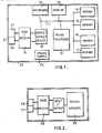
- a franking meter comprises a micro-processor 10 communicating via a system bus 11 with a keyboard 12, a display device 13 and memories 14, 15, 16 and 17.
- the keyboard is utilised by a user to input data to the meter and the display device 13 is provided for the display of an echo of the data input on the keyboard and for the display of instructional data to the user of the meter, for example relating to the operational status of the machine and to accounting data maintained by the meter.
- Operation of the microprocessor 10 is controlled by program routines stored in the read only memory 16.
- the memories 14 and 15 are utilised by the microprocessor to store accounting data relating to usage of the meter for franking.
- each item of data is stored in quadruplicate between the two memories.
- the memories 14 and 15 provide a number of registers for storing different items of accounting data.
- a credit register stores a value of credit available for use in franking operations
- a tote register stores a value of postage used in franking operations
- an item register stores a count of the number of items franked.
- the memory 17 is a random access memory used as a working store by the microprocessor.
- an input/output device 18 is connected to the system bus 11. While communication between the input/output device 18 and external devices may be by way of a multi-way plug and socket connection and electrical cables, it is preferred in accordance with the present invention to provide such communication by means of radiation links in which signals are transmitted from one device by a generator of radiation into the ambient environment of the devices and received at another device by a receiver responsive to that radiation. Accordingly the input/output device 18 is connected to a send/receive circuit 19. A send transducer 20 and a receive transducer 21 are connected to an output and input respectively of the send/receive circuit 19.
- the send/receive circuit energises the send transducer 20 such that the radiation generated by the transducer is modulated by the data being transmitted.
- the electronic circuit blocks of the franking meter are housed in a secure housing 22 to prevent unauthorised access to the circuits.
- a window 23 is provided in the wall of the housing and the send and receive transducers 21, 22 are located immediately behind this window.
- the window is constructed of a material which is substantially transparent to radiation transmitted by the send transducer and to radiation to which the receive transducer is responsive.
- the window forms a continuation of the wall of the secure housing and therefore the security of the housing is not breached as when an electrical connector extending through an aperture in the wall of the housing needs to be provided for connection to electrical cables.
- a power supply device 24, which may be powered from a mains electrical power supply, is utilised to energise the electronic circuits of the franking meter.
- FIG. 2 shows a block circuit diagram of an external device intended for communicating with the franking meter described hereinbefore.
- the device may be any one of a number of devices, for example a weighscale, computer, printer or modem, with which communication with the franking meter is desired.
- the device as shown in Figure 2 comprises electronic circuits 25 which are specific to the particular device for carrying out the functions of that device. If the device is a weighscale, the circuits 25 would include means responsive to weight of a mail item and for generating digital output signals representing weight data.
- the device may be provided with a keyboard and display to enable local operation of the device or the circuits include means responsive to receipt of control signals to enable remote operation of the device.
- a send/receive circuit 26 similar in construction and operation to the send/receive circuit 19 in the franking meter, is connected to the circuits 25.
- a send transducer 27 and a receive transducer 28 are connected to the output and input respectively of the send/receive circuit 26.
- the franking meter and external device or devices are located relative to one another such that radiation transmitted by the send transducers of the franking meter and the external device or devices is received by the receive transducers of the external device or devices and the franking meter respectively communication is established between the franking meter and the external devices and data signals may be transmitted therebetween.
- the radiation may be of ultra sonic or radio frequency.
- a franking meter 29 and modem 30, for connecting the meter to a telephone network are located in one part of an office 31 and a weighscale 32 and printer 33 are located in a mail handling room 34 separated from the office by a wall or partition 35.
- a satellite device 36 may be provided in a location such that reliable communication can be achieved between it and the franking meter 29 and between it and the devices 32, 33.
- the satellite device 36 receives radiation signals from the franking meter 29 and from the external devices 32, 33 and re-transmits the radiation signals to the external device and franking meter respectively. If desired the satellite may be utilised not only to re-transmit radiation signals but it may be connected to an external device.
- the external device may be adjacent the satellite and if desired the satellite and external device to which it is connected may be combined into an integral unit.
- the satellite may be connected by electrical cable 37 to an external device 38 remote from the satellite, for example situated in another part of a building, to enable data signals to be transmitted between the franking machine and the remote device 38.
- the satellite may be constructed as shown in Figure 4 and be operative to receive signals from the franking meter and from all of the external devices and to re-transmit radiation signals carrying the received data substantially simultaneously.
- the satellite comprises a receiver 40 responsive to the radiation signals to produce electrical signals which are input by connection 41 to transmitter 42 to be re-transmitted.
- the simultaneous retransmission of radiation signals may result in interference between signals. If the radiation is infra-red this is believed not to result in any problems. However if the radiation is of radio frequency, the interference may result in partial or total cancellation of the radiation signals. Accordingly in circumstances where simultaneous reception and transmission of radiation signals results in poor or unreliable communication, the satellite is constructed to delay re-transmission of radiation signals.
- the data when radiation signals carrying data are received by the receiver 40 of the satellite the data is stored in memory 43 in the satellite and, after a delay determined by a control circuit 44, the data is read from memory 43 and modulates a carrier generated and transmitted by transmitter 42. Thus retransmission of data is delayed until after receipt of that data so that reception and re-transmission are not simultaneous. It will be appreciated that, depending upon protocols utilised in communication, the control circuit 44 may cause re-transmission to be effected after reception of each complete data block or after reception of a complete message.
- the memory 43 is of appropriate capacity to temporarily store the data blocks or messages.
- Interference signals may result in corruption and loss of integrity of the data in transmission between the transmitter and the receiver. Accordingly in order to prevent such corrupted data from being accepted as data by the receiving device, a check on the data is carried out by the receiving device. This may be accomplished by causing the transmitting device to transmit each data block twice. The received blocks of a pair are compared for equality and if they are equal the data block is accepted.
- Figure 6 illustrates the writing of a data block received serially bit by bit in a first transmission thereof into a first register 46 while the data block received in a second transmission thereof is written into a second register 47. The data blocks written into registers 46, 47 are read out to a comparator 48.
- the comparator If the data blocks read from both registers are identical, the comparator outputs a data acceptance signal on line 49 to cause acceptance of the data block as being a valid data block. However if the data blocks from the registers are not identical, the comparator does not output the data acceptance signal and as a result the received data block is rejected and the sending unit will be requested to repeat the transmission of that data block.
- the second transmission of a data block may be effected in reverse order to that of the first transmission of that block.
- the receiving device compares the first transmission of the block with the second transmission but in reverse order.
- the data block in one register is read out in reverse order to that in which the data block was written into that register.
- register 47 is read out in reverse order.
- each block of data may be transmitted with check sum and/or parity bits to provide an additional check on integrity of the received data block.
- the franking meter may act as master device of the franking machine system and all communications may be controlled by and be to and from the franking meter. However if desired, one of the devices external to the franking meter may act as master device of the system and control communication between devices and between devices and the franking meter.
Landscapes
- Physics & Mathematics (AREA)
- General Physics & Mathematics (AREA)
- Arrangements For Transmission Of Measured Signals (AREA)
- Radio Relay Systems (AREA)
Applications Claiming Priority (2)
| Application Number | Priority Date | Filing Date | Title |
|---|---|---|---|
| GB888830418A GB8830418D0 (en) | 1988-12-30 | 1988-12-30 | Franking system |
| GB8830418 | 1988-12-30 |
Publications (2)
| Publication Number | Publication Date |
|---|---|
| EP0376574A2 true EP0376574A2 (de) | 1990-07-04 |
| EP0376574A3 EP0376574A3 (de) | 1990-11-28 |
Family
ID=10649283
Family Applications (1)
| Application Number | Title | Priority Date | Filing Date |
|---|---|---|---|
| EP19890313223 Withdrawn EP0376574A3 (de) | 1988-12-30 | 1989-12-18 | Frankiersystem |
Country Status (2)
| Country | Link |
|---|---|
| EP (1) | EP0376574A3 (de) |
| GB (1) | GB8830418D0 (de) |
Cited By (3)
| Publication number | Priority date | Publication date | Assignee | Title |
|---|---|---|---|---|
| US5657689A (en) * | 1995-01-04 | 1997-08-19 | Neopost Limited | Franking machine system |
| FR2829269A1 (fr) * | 2001-08-31 | 2003-03-07 | Neopost Ind | Systeme modulaire universel de traitement de courrier |
| EP1371024A4 (de) * | 2001-02-23 | 2007-05-23 | Ascom Hasler Mailing Sys Inc | Internet-frankierungssystem |
Family Cites Families (7)
| Publication number | Priority date | Publication date | Assignee | Title |
|---|---|---|---|---|
| US4138735A (en) * | 1977-01-31 | 1979-02-06 | Pitney-Bowes, Inc. | System for remotely resetting postage rate memories |
| US4251874A (en) * | 1978-10-16 | 1981-02-17 | Pitney Bowes Inc. | Electronic postal meter system |
| US4326254A (en) * | 1979-03-07 | 1982-04-20 | Tokyo Electric Co., Ltd. | Postal charge processing system |
| FR2565720B3 (fr) * | 1984-06-06 | 1986-12-12 | Etude Const App Precision | Systeme de collecte de donnees en provenance de machines a affranchir |
| US4649491A (en) * | 1984-12-20 | 1987-03-10 | Pitney Bowes Inc. | Modular battery powered business systems |
| GB2173741B (en) * | 1985-04-17 | 1989-07-05 | Pitney Bowes Inc | Unsecured postage applying system and method |
| US4812992A (en) * | 1986-04-10 | 1989-03-14 | Pitney Bowes Inc. | Postage meter communication system |
-
1988
- 1988-12-30 GB GB888830418A patent/GB8830418D0/en active Pending
-
1989
- 1989-12-18 EP EP19890313223 patent/EP0376574A3/de not_active Withdrawn
Cited By (6)
| Publication number | Priority date | Publication date | Assignee | Title |
|---|---|---|---|---|
| US5657689A (en) * | 1995-01-04 | 1997-08-19 | Neopost Limited | Franking machine system |
| EP0721173A3 (de) * | 1995-01-04 | 1999-07-07 | Neopost Limited | Frankiermaschinensystem |
| EP1371024A4 (de) * | 2001-02-23 | 2007-05-23 | Ascom Hasler Mailing Sys Inc | Internet-frankierungssystem |
| FR2829269A1 (fr) * | 2001-08-31 | 2003-03-07 | Neopost Ind | Systeme modulaire universel de traitement de courrier |
| EP1293936A1 (de) * | 2001-08-31 | 2003-03-19 | Neopost Industrie | Modulares und universelles System zur Postbehandlung |
| US7809654B2 (en) | 2001-08-31 | 2010-10-05 | Neopost Industrie | Universal modular mail handling system |
Also Published As
| Publication number | Publication date |
|---|---|
| EP0376574A3 (de) | 1990-11-28 |
| GB8830418D0 (en) | 1989-03-01 |
Similar Documents
| Publication | Publication Date | Title |
|---|---|---|
| US5323323A (en) | Franking machine system | |
| US4301507A (en) | Electronic postage meter having plural computing systems | |
| US4907271A (en) | Secure transmission of information between electronic stations | |
| EP0550226B1 (de) | Verfahren und System zur Fernauffüllung des Guthabenspeichers einer Frankiermaschine | |
| US5206812A (en) | Franking machine | |
| US5822738A (en) | Method and apparatus for a modular postage accounting system | |
| CA1164566A (en) | Serial communications bus for remote terminals | |
| US4430716A (en) | Postage value determining scale with expandable memory port | |
| GB2232121A (en) | Remotely controlling the dispensing of aggregate postage on a batch basis. | |
| US4422148A (en) | Electronic postage meter having plural computing systems | |
| KR19980702437A (ko) | 프리 로우밍 원격 휴대용 매장 단말기 | |
| JPH0215899B2 (de) | ||
| AU670304B2 (en) | Electronic identification system with anti-tampering protection | |
| US6076081A (en) | Protocol converter with peripheral machine trip capability | |
| EP0851597A2 (de) | Verfahren und Vorrichtung zur Überprüfung der Kompatibilität von einem Mobilfunkstation und einem Zusatzeinheit | |
| EP0376574A2 (de) | Frankiersystem | |
| EP0298776B1 (de) | Frankiermaschinensystem | |
| US6188872B1 (en) | Method of checking and acknowledging reception of data in a two-way radio communication system | |
| GB2227453A (en) | Franking machine communication system | |
| EP0356052B1 (de) | Frankiermaschine | |
| EP0285390B1 (de) | Frankiermaschine | |
| JP3415982B2 (ja) | 無線検針システム | |
| EP0493949A2 (de) | Frankiermaschine | |
| KR970004473A (ko) | 무선 장치 및 상기 무선 장치로의 불법적 접근 기억 시스템 및 방법 | |
| US5719775A (en) | Franking machine and franking machine system |
Legal Events
| Date | Code | Title | Description |
|---|---|---|---|
| PUAI | Public reference made under article 153(3) epc to a published international application that has entered the european phase |
Free format text: ORIGINAL CODE: 0009012 |
|
| AK | Designated contracting states |
Kind code of ref document: A2 Designated state(s): DE FR GB |
|
| PUAL | Search report despatched |
Free format text: ORIGINAL CODE: 0009013 |
|
| AK | Designated contracting states |
Kind code of ref document: A3 Designated state(s): DE FR GB |
|
| STAA | Information on the status of an ep patent application or granted ep patent |
Free format text: STATUS: THE APPLICATION IS DEEMED TO BE WITHDRAWN |
|
| 18D | Application deemed to be withdrawn |
Effective date: 19910529 |