EP0376597A2 - Sélection de paquets par des dispositifs de distributions de paquets - Google Patents
Sélection de paquets par des dispositifs de distributions de paquets Download PDFInfo
- Publication number
- EP0376597A2 EP0376597A2 EP89313323A EP89313323A EP0376597A2 EP 0376597 A2 EP0376597 A2 EP 0376597A2 EP 89313323 A EP89313323 A EP 89313323A EP 89313323 A EP89313323 A EP 89313323A EP 0376597 A2 EP0376597 A2 EP 0376597A2
- Authority
- EP
- European Patent Office
- Prior art keywords
- destination
- packet
- packets
- arrangement
- usage
- Prior art date
- Legal status (The legal status is an assumption and is not a legal conclusion. Google has not performed a legal analysis and makes no representation as to the accuracy of the status listed.)
- Granted
Links
Images

Classifications
-
- H—ELECTRICITY
- H04—ELECTRIC COMMUNICATION TECHNIQUE
- H04L—TRANSMISSION OF DIGITAL INFORMATION, e.g. TELEGRAPHIC COMMUNICATION
- H04L49/00—Packet switching elements
- H04L49/30—Peripheral units, e.g. input or output ports
-
- H—ELECTRICITY
- H04—ELECTRIC COMMUNICATION TECHNIQUE
- H04L—TRANSMISSION OF DIGITAL INFORMATION, e.g. TELEGRAPHIC COMMUNICATION
- H04L49/00—Packet switching elements
- H04L49/25—Routing or path finding in a switch fabric
- H04L49/253—Routing or path finding in a switch fabric using establishment or release of connections between ports
- H04L49/254—Centralised controller, i.e. arbitration or scheduling
-
- H—ELECTRICITY
- H04—ELECTRIC COMMUNICATION TECHNIQUE
- H04L—TRANSMISSION OF DIGITAL INFORMATION, e.g. TELEGRAPHIC COMMUNICATION
- H04L49/00—Packet switching elements
- H04L49/40—Constructional details, e.g. power supply, mechanical construction or backplane
Definitions
- This invention relates to input arrangements for packet networks and particularly to distributed arrangements for selecting input packets for transmission to packet destinations based on the availability or unavailability of packet destinations for receiving packets.
- Packet switching arrangements have proven to be preferred switching networks for many types of digital communication. Data packets each comprising a data portion and a numerical designation of a packet destination are applied to the inputs of such a network and the network conveys each packet to the identified destination.
- packet networks tends to be bursty. During some periods of time many packets arrive for distribution and at other times few packets arrive. For economic reasons packet networks for switching bursty traffic are engineered to convey an average rate of traffic rather than the maximum rate. Such networks include packet buffering before, within or on the outputs of the actual switch network to help average the traffic rates.
- Buffering packets at the input to the network is advantageous since it permits the use of simple network architectures such as the sort-then-expand (also called Batcher-Banyan) networks.
- Known input buffering arrangements select packets from a plurality of parallel input buffers based on first-in-first-out rules or based on packet priorities. This results in the "blind" transmission of packets where packets are sent to the network without certainty that the packet destination will be available when the packet arrives. Such blind transmission results in wasted network resources and low network throughput since packets which cannot be used by busy destinations are transmitted to the network.
- Centralized arrangements have been constructed to select packets for distribution based on destination availability. With such arrangements a single unit accumulates all incoming packets, or information about the destinations of all incoming packets, and selects packets based on the destination information of all accumulated packets and the availability of packet destinations. Given the total number of packets to be considered and the number of selections to be made, such centralized arrangements are slow compared to the packet rates of commercial high capacity distribution systems and limit their packet distribution rate.
- a packet selection arrangement including a plurality of input units, each storing a plurality of packets, and an arrangement for providing each input unit with a plurality of destination addresses each associated with a destination usage indicator.
- a selector in each input unit selects one of the plurality of packets stored thereby when a provided destination address matches the destination information of a stored packet and the destination usage indicator associated with the provided destination address indicates destination availability.
- Packet selection performed by a plurality of input units, each simultaneously performing a part of the overall packet selection function provides high speed operation which is compatible with commercial high capacity packet systems.
- the ability to select only one packet for each destination is improved in accordance with one aspect of the invention in which the address providing arrangement contemporaneously supplies a different one of the plurality of addresses, and its associated usage indicator, to each input unit.
- Single packet selection is also enhanced when the selection arrangement marks a matching destination address unavailable, by modifying its associated usage indicator to indicate unavailability, and subsequent input units are inhibited from selecting packets for packet destinations which are associated with usage indicators indicating unavailability.
- one embodiment inhibits the selection of more than one packet by an input unit after that input unit selects a packet.
- An illustrative embodiment achieves additional speed advantages by distributing the function of providing destination addresses to each input unit.
- Each input unit includes a counter which is incremented at regular intervals (called select intervals) to provide a series of destination addresses.
- select intervals regular intervals
- a different start value is initially established in each counter. This initial value is derived in the input units from a unique identity preassigned to each input unit.
- a random number is generated and sent to all input units and each initial counter value is derived by adding the random number to the preassigned identity.
- counters for providing a plurality of destination addresses permits the selection of the number of destination addresses provided to each input unit by the choice of the number of select interval signals generated.
- the addresses of all destinations are provided by generating a number of select interval signals equal to the number of destinations.
- the usage indicators which define the availability or unavailability of packet destinations are conveyed from input means to input means in synchronism with the select intervals.
- the packet destination addresses stored by the counters of the input means comprise an arithmetic series and the input units are connected in reverse order of this series for the transmission of usage indicators.
- an input means includes a unique destination address in its counter and receives the usage indicator associated with that unique address from the input means which included that address during the preceding select interval. This maintains the association of destination addresses and usage indicators.
- the value of the usage indicator transmitted from one input unit to the next is controlled by the transmitting input unit.
- the usage indicator transmitted to the next input unit is the same as the usage indicator received by the transmitting input unit during the preceding select interval.
- the usage indicator transmitted to the next input means during the next select interval indicates destination address unavailability.
- a part of packet selection is the comparison of the provided destination address from the counter with the destination information of a plurality of stored packets.
- each input unit includes a plurality of comparators, each of which compares the destination information of one stored packet with the provided destination address from the counter. This parallel comparison rapidly provides comparison results which are used in packet selection and also in the update of destination usage indicators.
- Status indicators are provided to input units of the embodiments to indicate the availability of individual ones of the packet destinations to receive packets.
- An enabling arrangement in each input unit is controllable by the status indicators to enable the selection of packets for transmission from each input means to only one destination at a time.
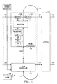
- FIG. 1 is a block diagram of an embodiment of the present invention which includes a packet switching network 101 having 16 input ports 102 and 16 output ports 103.
- Network 101 is of the type described in Huang et. al. U. S. Patent No. 4,516,238 and is non-blocking for sets of input packets which include only one packet for each network output port.
- Each input port 102 is connected to an incoming packet communication path 104 by a trunk controller 105 which receives and stores incoming packets from its associated communication path 104 in a buffer 108 and selects packets from buffer 108 for transmission to the connected input 102.
- the trunk controllers 105 of FIG. 1 operate in synchronism to simultaneously transmit packets to network 101 at the beginning of a packet interval.
- Packet intervals are recurring periods of time which are defined by signals from a clock circuit 106 and are long enough to permit the transmission of an entire packet before the beginning of a subsequent packet interval.
- Each trunk controller 105 comprises a buffer 108 for storing incoming packets, a selector 109 for selecting a buffered packet for transmission to the network 101 and an output register 110 for holding the selected packet prior to transmission. Trunk controllers cooperate in the selection of packets so that no two packets transmitted to network 101 during a packet interval are destined for the same network output port 103. Such pre-selection eliminates packet blocking in the network 101 and provides improved network throughput.
- each trunk controller 105 During each packet interval, the selector 109 of each trunk controller 105 is provided with the address of each output port 103 in association with a usage indication of the availability or unavailability, during the next packet interval, of the output port represented by the address. A particular address is presented to only one selector 109 at a time and when a selector selects a packet for a particular destination output the selector also marks the address representing that output port as unavailable to other trunk controllers 105. Before the next packet interval begins each trunk controller moves the packet selected thereby, if any, to output register 110 for transmission to network 101 during the next packet interval.
- selector 109 compares a provided destination address representing an output port 103 with the destination information of a predetermined number of packets from buffer 108 to determine if one of these packets is destined for the output port represented by the destination address.
- the choice of predetermined number of packets for comparison is made by the designer. A large predetermined number provides the highest throughput but also results in a complex and possibly slow selector 109. A smaller predetermined number yields a simpler selector 109 but may result in small throughput improvement.
- Table 1 represents simulated results for maximum throughput versus predetermined number for 128 X 128 switch. A throughput of 59 percent means that 59 percent of the transmitted packets are not blocked.
- Table 1 Predetermined Number Maximum Throughput (%) 1 59 2 71 4 81 8 88 16 93
- the presented destination addresses are compared with the destination information of four buffered packets in selector 109; that is, the predetermined number equals four.
- Each packet interval is divided into a number of select intervals (FIG. 3) equal to the number of packet destinations.
- the packet interval is divided into 16 select intervals since there are 16 output ports 103 in the present embodiment.
- selector 109 receives the destination address of one output port 103 and a usage signal on a conductor 120 defining the availability or unavailability of that output port during the next packet interval.
- each selector will have checked for packets destined to all output ports 103.
- Each trunk controller 105 includes a binary counter 115 which is used to provide a sequence of destination addresses for that trunk controller.
- Counter 115 comprises 4-bit positions which is sufficient to denote the addresses of all of the output ports 103.
- each counter 115 is loaded with a binary value which is unique to the trunk controller 105 including it. This unique value is derived from a unique trunk controller identity which is preassigned to each trunk controller and stored in an identity register 116.
- the assigned identities of the trunk controllers 105 in FIG. 1 are "0000" for the top trunk controller, "0001" through “1110” in sequence for the intermediate 14 trunk controllers (not shown) and "1111" for the bottom trunk controller.
- a random number from random number generator 117 is added (modulo 16) in an adder 118 to each trunk controller identity and the result is transmitted to counter 115 via a conductor 119.
- the addition of the random number to the trunk controller identity results in counters 115 storing the values "0000" through “1111” in sequence but the actual value in any counter 115 is determined by the random number. This improves the fairness of packet selection randomly by changing the destination address provided to each selector 109 at the beginning of each packet interval.
- the value stored by comparator 115 represents the destination address of an output port 103 and is applied as an input to selector 109.
- Each selector 109 also receives a usage signal on conductor 120 defining whether the output port represented by the address in counter 115 is available or unavailable during the next packet interval.
- the usage signals are transmitted from selector to selector in a daisy chain fashion via the communication path 120.
- Each packet interval in the present example is divided into 16 select intervals numbered 0 through 15 as shown in FIG. 3.
- all selectors 109 receive a unique destination address from the counter 115 associated therewith and a usage signal on communication path 120 defining that the destination is available (no destinations have yet been selected).
- the destination address in counter 115 is compared with the destination address information of up to four packets from buffer 108.
- When no match is found the selector 109 takes no action, however, when a match is found selector 109 moves the matching packet from buffer 108 to output register 110, generates an inhibit signal, internal to the generating selector 109, and generates a usage signal defining the unavailability of the selected destination.
- the inhibit signal is generated by the ones of selectors 109 which detect a match and is used to inhibit further packet selection by the generating selector until the next packet interval.
- Clock circuit 106 begins the second select interval by generating a counter increment signal which is sent to each counter 115 via a conductor 121.
- Counter 115 responds to the increment signal by adding 1 (modulo 16) to the counter value to present the next higher designation to each selector 109.
- each selector 109 also transmits a new usage signal to the next selector in the sequence.
- the new usage signal indicates availability when the generating selector did not select a packet during the preceding (first) select interval and indicates unavailability when the generating selector selected a packet during the preceding select interval.
- a selector 109 receiving a usage signal defining unavailability does not select a packet even if the destination information one of the packets stored thereby matches the counter value. Any selector receiving a usage signal defining availability selects a packet (if a match exists) in the manner described above.
- Each counter 115 is again incremented at the beginning at the third select interval and a new usage signal is transmitted from one selector to the next in the sequence.
- the new usage signal indicates destination availability when no prior selector (including the selector generating the signal) has selected the destination represented by the counter 115 of the receiving selector 109.
- the new usage signal indicates destination unavailability when any prior selector (including the selector generating the signal) has selected the destination represented in the counter 115 of the receiving selector 109.
- select intervals continue as described until the end of the 16th interval when all destination addresses and their associated usage signals have been presented to each selector 109.
- output registers 110 of trunk controllers 105 contain all of the packets selected during the packet interval.
- a new selection phase begins by resetting all usage signals to indicate availability and resetting the inhibit signals, internal to the selectors 109, so that all selectors can again select the packets.
- the above cycle of select intervals repeats during the next packet interval and packets selected during the preceding packet interval are transmitted to network 101.
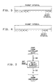
- the packet interval shown in FIG. 3 is divided into 16 equal select intervals 0 through 15 which occupy the entire packet interval.
- FIG. 4 shows an alternate division of the packet interval in which the 16th select interval ends prior to the end of the packet interval. This leaves time, after packet selection, to move packets to the output register 110 and to reset the inhibit and usage signals in each selector.
- FIG. 2 represents the structure of all trunk controllers 105 and shows the internal structure of selector 109.
- the input portion of usage signal communication path 120 is labeled 120-1 and the output portion of this communication path is labeled 120-2.
- Selector 109 includes four registers 126 and a controller 125 which reads representations of stored packets from buffer 108 and places one in each register 126.
- Each register 126 includes an address portion storing the destination address of a packet in buffer 108 and a pointer defining the location in buffer 108 which stores the packet having the destination address stored in the address portion.
- the address portion of each register 126 is applied as one input to an associated one of four comparators 128.
- Each comparator also receives the current numerical value of counter 115 via a path 129.
- Each comparator 128 sets an associated one of four flip-flops 130 to the "1" state when the value of counter 115 matches the address stored in the associated register 126.
- the outputs of flip-flops 130 are combined in an OR gate 132 so that the output of OR gate 132 will be a "1" when any of the address portions of register 126 match the value in counter 115.
- OR gate 132 is applied via a conductor 133 as an input to an AND gate 134, the other input of which is connected to an inhibit flip-flop 135.
- Inhibit flip-flop 135 is set to apply a "1" to AND gate 134 at the beginning of each packet interval and upon being reset, generates a "0" inhibit signal to inhibit the selection of a second packet during one packet interval.
- the output of AND gate 134 is the same as the output of OR gate 132 while flip-flop 135 is set to "1" and is "0" when flip-flop 135 is reset to "0".
- the output of AND gate 134 is applied and an input to an AND gate 136 and OR gate 137.
- OR gate 137 controls the destination usage signal that will be applied to the next selector during the immediately succeeding select interval.
- OR gate 137 receives as inputs the output of AND gate 134 and the usage signal from the preceding selector via conductor 120-1.
- the destination usage signal output of OR gate 137 is a "1" when a prior selector has selected the destination address now represented in counter 115 or when one of the addresses in registers 126 match the value of counter 115.
- the output of OR gate 137 is applied to the data input of a flip-flop 138. At the beginning of each select interval flip-flop 138 is toggled by a signal from clock circuit 106 on conductor 140 to store and transmit the usage signal at its data input to the next selector 109 via usage signal output path 120-2. It should be mentioned that flip-flop 138 is cleared to "0" indicating idle at the beginning of each packet interval.
- the usage signal from the previous selector 109 on conductor 120-1 is also applied via an inverter 139 to an input of AND gate 136.
- a strobe signal from clock 106 is applied to the remaining input 143 of AND gate 136, at the end of each select interval.
- the output of AND gate 136 is a "1" only if the usage signal on conductor 120-1 from the previous selector 109 indicates availability and the output of AND gate 134 is a "1" indicating a match of packet destinations. This combination of inputs occurs only when the destination represented by counter 115 is available and matches one of the addresses stored in registers 126.
- the "1" output from AND gate 136 indicates a packet selection and is applied via a conductor 142 to the reset input of flip-flop 135 and to controller 125.
- the "1" signal on conductor 142 resets flip-flop 135 to the zero state inhibiting the further selection of packets by the selector 109.
- All flip-flops 135 are set to the "1" state by a signal on conductor 141 from clock 106 at the beginning of each packet interval.
- the output of AND gate 136 is also sent via conductor 142 to notify controller 125 that a matching, available packet has been found. Controller 125 responds to a "1" on conductor 142 by inhibiting further comparison by comparators 128 and interrogating each of the flip-flops 130 via a communication path 144.
- a flip-flop 130 in the "1" state means that the address in the associated one of registers 126 matches the value of counter 115.
- controller 125 Upon detecting a flip-flop 130 in the "1" state controller 125 reads the pointer portion of the associated register 126 via a communication path 145 and uses that pointer to move a packet from buffer 108 to output register 110. After moving the packet to output register 110, controller 125 inserts a new address and packet pointer, representing another packet, into the register 126 which just matched.
- controller 125 places packet representations in registers 126 such that no other register 126 in the same selector 109 represents a packet for the same destination. This improves packet throughput. Controller 125 could, alternatively, place packet representations in registers 126 in the order in which packets are received by buffer 108. Since this permits packets having same destinations to be simultaneously represented in registers 126, controller 125 includes the ability to select one matching packet when more than one matching packet is detected.
- the network in the preceding example had the same number of trunk controllers and packet destination output ports.
- the present invention also improves packet throughput when the number of inputs and outputs are not equal. For example, when the number of inputs is 8 and the number of outputs is 16 the selectors 109 operate as a above described for packet selection.
- a delay unit (FIG. 5) equivalent to eight select intervals must be inserted into the usage signal path 120 to maintain the association of counter 115 values and the usage signals.
- the delay unit of FIG. 5 is connected serially into conductor 120 between the top most trunk controller 105 and the bottom most trunk controller 105.
- the delay unit is constructed from eight flip-flops which are controlled in the manner of the flip-flops 138 in each selector 109.
- the preceding description relates to the transmission of packets through a packet switching network.
- the principles in the invention apply equally well to the distribution of any data messages which include a destination address to any addressed utilization device or resource.
- destination usage signal (indicator) is used to denote any signals which identify the availability or unavailability of packet destinations.
- Such destination usage signals may be any busy/idle type status indicators which describe the availability of utilization devices.
Landscapes
- Engineering & Computer Science (AREA)
- Computer Networks & Wireless Communication (AREA)
- Signal Processing (AREA)
- Data Exchanges In Wide-Area Networks (AREA)
Applications Claiming Priority (2)
| Application Number | Priority Date | Filing Date | Title |
|---|---|---|---|
| US291487 | 1988-12-29 | ||
| US07/291,487 US4937817A (en) | 1988-12-29 | 1988-12-29 | Packet selection for packet distribution arrangements |
Publications (3)
| Publication Number | Publication Date |
|---|---|
| EP0376597A2 true EP0376597A2 (fr) | 1990-07-04 |
| EP0376597A3 EP0376597A3 (fr) | 1991-07-17 |
| EP0376597B1 EP0376597B1 (fr) | 1995-03-22 |
Family
ID=23120501
Family Applications (1)
| Application Number | Title | Priority Date | Filing Date |
|---|---|---|---|
| EP89313323A Expired - Lifetime EP0376597B1 (fr) | 1988-12-29 | 1989-12-20 | Sélection de paquets par des dispositifs de distributions de paquets |
Country Status (4)
| Country | Link |
|---|---|
| US (1) | US4937817A (fr) |
| EP (1) | EP0376597B1 (fr) |
| JP (1) | JPH0779352B2 (fr) |
| DE (1) | DE68921864T2 (fr) |
Cited By (2)
| Publication number | Priority date | Publication date | Assignee | Title |
|---|---|---|---|---|
| WO1998020652A1 (fr) * | 1996-11-08 | 1998-05-14 | Integrated Telecom Technology, Inc. | Procede et appareil pour detecter des peripheriques physiques invalides et supprimer des cellules perimees |
| US6134218A (en) * | 1994-04-28 | 2000-10-17 | Pmc-Sierra (Maryland), Inc. | Many dimensional congestion detection system and method |
Families Citing this family (13)
| Publication number | Priority date | Publication date | Assignee | Title |
|---|---|---|---|---|
| US5179558A (en) * | 1989-06-22 | 1993-01-12 | Digital Equipment Corporation | Routing apparatus and method for high-speed mesh connected local area network |
| GB8915137D0 (en) * | 1989-06-30 | 1989-08-23 | Inmos Ltd | Message routing |
| US5422881A (en) * | 1989-06-30 | 1995-06-06 | Inmos Limited | Message encoding |
| GB8915135D0 (en) * | 1989-06-30 | 1989-08-23 | Inmos Ltd | Message routing |
| JPH0828746B2 (ja) * | 1989-08-23 | 1996-03-21 | 日本電気株式会社 | パケット交換システムにおける端末収容回路のアドレス設定・フィルタリング方式 |
| DE3942977A1 (de) * | 1989-12-23 | 1991-06-27 | Standard Elektrik Lorenz Ag | Verfahren zum wiederherstellen der richtigen zellfolge, insbesondere in einer atm-vermittlungsstelle, sowie ausgangseinheit hierfuer |
| US5327534A (en) * | 1990-07-30 | 1994-07-05 | Digital Equipment Corporation | Detection of duplicate alias addresses |
| US5267235A (en) * | 1992-05-21 | 1993-11-30 | Digital Equipment Corporation | Method and apparatus for resource arbitration |
| US5590292A (en) * | 1992-12-08 | 1996-12-31 | Compaq Computer Corporation | Scalable tree structured high speed input/output subsystem architecture |
| US7058063B1 (en) | 1999-06-18 | 2006-06-06 | Nec Corporation | Pipelined packet scheduler for high speed optical switches |
| US7743125B1 (en) * | 2000-11-09 | 2010-06-22 | General Electric Company | Computer multiple communications port unit |
| US7103019B1 (en) * | 2001-03-21 | 2006-09-05 | Cisco Technology, Inc. | Error correction using redundant packet streams in wireless communications systems |
| US20030076784A1 (en) * | 2001-10-24 | 2003-04-24 | Zarlink Semiconductor V.N. Inc. | Methods of performance estimation in provisioning delay intolerant data services |
Family Cites Families (4)
| Publication number | Priority date | Publication date | Assignee | Title |
|---|---|---|---|---|
| US4611322A (en) * | 1984-08-03 | 1986-09-09 | At&T Bell Laboratories | Traffic load control arrangement and method for a packet switching system |
| EP0219049B1 (fr) * | 1985-10-07 | 1992-09-02 | Nec Corporation | Système de communication à commutation de paquets à grande vitesse avec commande du flux de bout en bout et avec retransmission |
| US4780870A (en) * | 1986-09-05 | 1988-10-25 | American Telephone And Telegraph Company, At&T Bell Laboratories | Packet switch |
| US4761780A (en) | 1986-12-22 | 1988-08-02 | Bell Communications Research, Inc. | Enhanced efficiency Batcher-Banyan packet switch |
-
1988
- 1988-12-29 US US07/291,487 patent/US4937817A/en not_active Expired - Lifetime
-
1989
- 1989-12-20 EP EP89313323A patent/EP0376597B1/fr not_active Expired - Lifetime
- 1989-12-20 DE DE68921864T patent/DE68921864T2/de not_active Expired - Fee Related
- 1989-12-27 JP JP33683789A patent/JPH0779352B2/ja not_active Expired - Lifetime
Cited By (2)
| Publication number | Priority date | Publication date | Assignee | Title |
|---|---|---|---|---|
| US6134218A (en) * | 1994-04-28 | 2000-10-17 | Pmc-Sierra (Maryland), Inc. | Many dimensional congestion detection system and method |
| WO1998020652A1 (fr) * | 1996-11-08 | 1998-05-14 | Integrated Telecom Technology, Inc. | Procede et appareil pour detecter des peripheriques physiques invalides et supprimer des cellules perimees |
Also Published As
| Publication number | Publication date |
|---|---|
| JPH0779352B2 (ja) | 1995-08-23 |
| JPH02237337A (ja) | 1990-09-19 |
| DE68921864T2 (de) | 1995-10-26 |
| DE68921864D1 (de) | 1995-04-27 |
| EP0376597B1 (fr) | 1995-03-22 |
| EP0376597A3 (fr) | 1991-07-17 |
| US4937817A (en) | 1990-06-26 |
Similar Documents
| Publication | Publication Date | Title |
|---|---|---|
| US4937817A (en) | Packet selection for packet distribution arrangements | |
| KR970000792B1 (ko) | 패킷 스위치 및 그 구조 | |
| US4899334A (en) | Self-routing multistage switching network for fast packet switching system | |
| KR100334922B1 (ko) | 효율적인출력요구패킷스위치와방법 | |
| US5008878A (en) | High-speed modular switching apparatus for circuit and packet switched traffic | |
| US5291482A (en) | High bandwidth packet switch | |
| EP0471344B1 (fr) | Méthode et circuit de mise en forme du trafic | |
| US5361255A (en) | Method and apparatus for a high speed asynchronous transfer mode switch | |
| CN1097913C (zh) | Atm流量调节 | |
| US20080267206A1 (en) | Cam based system and method for re-sequencing data packets | |
| JP2882384B2 (ja) | トラヒックシェーピング装置 | |
| EP0611014A2 (fr) | Dispositif de communication | |
| US6791992B1 (en) | Earliest-deadline-first queuing cell switching architecture and method | |
| EP0404443A2 (fr) | Planification du routage des paquets dans un système de commutation interconnecté de paquets pour des paquets périodiques ou aléatoires | |
| US4930122A (en) | Message transfer system and method | |
| US4891802A (en) | Method of and circuit arrangement for controlling a switching network in a switching system | |
| JP3087123B2 (ja) | 交換回路網 | |
| US5828654A (en) | ATM cell policing method and apparatus | |
| US6445706B1 (en) | Method and device in telecommunications system | |
| EP1220497B1 (fr) | Commutateur de paquet | |
| JPH04234248A (ja) | パケット配送装置 | |
| EP1284070B1 (fr) | Procede et unite d'arbitrage pour commutateur numerique | |
| US6490640B1 (en) | Packet data switching apparatus | |
| US6212181B1 (en) | Method for using the departure queue memory bandwidth to support additional cell arrivals in an ATM switch | |
| JP3335069B2 (ja) | 固定長セル多重伝送装置,固定長セル多重伝送方法,固定長セル送信装置及び固定長セル多重装置 |
Legal Events
| Date | Code | Title | Description |
|---|---|---|---|
| PUAI | Public reference made under article 153(3) epc to a published international application that has entered the european phase |
Free format text: ORIGINAL CODE: 0009012 |
|
| AK | Designated contracting states |
Kind code of ref document: A2 Designated state(s): DE FR GB IT |
|
| PUAL | Search report despatched |
Free format text: ORIGINAL CODE: 0009013 |
|
| AK | Designated contracting states |
Kind code of ref document: A3 Designated state(s): DE FR GB IT |
|
| 17P | Request for examination filed |
Effective date: 19920109 |
|
| 17Q | First examination report despatched |
Effective date: 19931025 |
|
| RAP3 | Party data changed (applicant data changed or rights of an application transferred) |
Owner name: AT&T CORP. |
|
| GRAA | (expected) grant |
Free format text: ORIGINAL CODE: 0009210 |
|
| AK | Designated contracting states |
Kind code of ref document: B1 Designated state(s): DE FR GB IT |
|
| REF | Corresponds to: |
Ref document number: 68921864 Country of ref document: DE Date of ref document: 19950427 |
|
| ET | Fr: translation filed | ||
| ITF | It: translation for a ep patent filed | ||
| PLBE | No opposition filed within time limit |
Free format text: ORIGINAL CODE: 0009261 |
|
| STAA | Information on the status of an ep patent application or granted ep patent |
Free format text: STATUS: NO OPPOSITION FILED WITHIN TIME LIMIT |
|
| 26N | No opposition filed | ||
| PGFP | Annual fee paid to national office [announced via postgrant information from national office to epo] |
Ref country code: FR Payment date: 20011121 Year of fee payment: 13 |
|
| PGFP | Annual fee paid to national office [announced via postgrant information from national office to epo] |
Ref country code: GB Payment date: 20011126 Year of fee payment: 13 |
|
| REG | Reference to a national code |
Ref country code: GB Ref legal event code: IF02 |
|
| PG25 | Lapsed in a contracting state [announced via postgrant information from national office to epo] |
Ref country code: GB Free format text: LAPSE BECAUSE OF NON-PAYMENT OF DUE FEES Effective date: 20021220 |
|
| GBPC | Gb: european patent ceased through non-payment of renewal fee |
Effective date: 20021220 |
|
| PG25 | Lapsed in a contracting state [announced via postgrant information from national office to epo] |
Ref country code: FR Free format text: LAPSE BECAUSE OF NON-PAYMENT OF DUE FEES Effective date: 20030901 |
|
| REG | Reference to a national code |
Ref country code: FR Ref legal event code: ST |
|
| PGFP | Annual fee paid to national office [announced via postgrant information from national office to epo] |
Ref country code: DE Payment date: 20050121 Year of fee payment: 16 |
|
| PG25 | Lapsed in a contracting state [announced via postgrant information from national office to epo] |
Ref country code: IT Free format text: LAPSE BECAUSE OF NON-PAYMENT OF DUE FEES;WARNING: LAPSES OF ITALIAN PATENTS WITH EFFECTIVE DATE BEFORE 2007 MAY HAVE OCCURRED AT ANY TIME BEFORE 2007. THE CORRECT EFFECTIVE DATE MAY BE DIFFERENT FROM THE ONE RECORDED. Effective date: 20051220 |
|
| PG25 | Lapsed in a contracting state [announced via postgrant information from national office to epo] |
Ref country code: DE Free format text: LAPSE BECAUSE OF NON-PAYMENT OF DUE FEES Effective date: 20060701 |