EP0376646A2 - Système pour la radiotransmission des indications du niveau d'un liquide et pour la conversion des indications reçues en indications de volume pour l'affichage - Google Patents
Système pour la radiotransmission des indications du niveau d'un liquide et pour la conversion des indications reçues en indications de volume pour l'affichage Download PDFInfo
- Publication number
- EP0376646A2 EP0376646A2 EP89313512A EP89313512A EP0376646A2 EP 0376646 A2 EP0376646 A2 EP 0376646A2 EP 89313512 A EP89313512 A EP 89313512A EP 89313512 A EP89313512 A EP 89313512A EP 0376646 A2 EP0376646 A2 EP 0376646A2
- Authority
- EP
- European Patent Office
- Prior art keywords
- data
- liquid level
- microcomputer
- signals
- cell
- Prior art date
- Legal status (The legal status is an assumption and is not a legal conclusion. Google has not performed a legal analysis and makes no representation as to the accuracy of the status listed.)
- Granted
Links
Images





Classifications
-
- G—PHYSICS
- G01—MEASURING; TESTING
- G01F—MEASURING VOLUME, VOLUME FLOW, MASS FLOW OR LIQUID LEVEL; METERING BY VOLUME
- G01F23/00—Indicating or measuring liquid level or level of fluent solid material, e.g. indicating in terms of volume or indicating by means of an alarm
- G01F23/30—Indicating or measuring liquid level or level of fluent solid material, e.g. indicating in terms of volume or indicating by means of an alarm by floats
-
- G—PHYSICS
- G01—MEASURING; TESTING
- G01F—MEASURING VOLUME, VOLUME FLOW, MASS FLOW OR LIQUID LEVEL; METERING BY VOLUME
- G01F23/00—Indicating or measuring liquid level or level of fluent solid material, e.g. indicating in terms of volume or indicating by means of an alarm
- G01F23/30—Indicating or measuring liquid level or level of fluent solid material, e.g. indicating in terms of volume or indicating by means of an alarm by floats
- G01F23/40—Indicating or measuring liquid level or level of fluent solid material, e.g. indicating in terms of volume or indicating by means of an alarm by floats using bands or wires as transmission elements
- G01F23/44—Indicating or measuring liquid level or level of fluent solid material, e.g. indicating in terms of volume or indicating by means of an alarm by floats using bands or wires as transmission elements using electrically actuated indicating means
-
- G—PHYSICS
- G01—MEASURING; TESTING
- G01F—MEASURING VOLUME, VOLUME FLOW, MASS FLOW OR LIQUID LEVEL; METERING BY VOLUME
- G01F23/00—Indicating or measuring liquid level or level of fluent solid material, e.g. indicating in terms of volume or indicating by means of an alarm
- G01F23/80—Arrangements for signal processing
Definitions
- the invention relates to system for radio transmission of level data of liquid, such as fuel which is contained in a tank, above all the underground tank and for receiving the data to convert to volume data to be indicated for relevantly control liquid volume.
- level data of liquid such as fuel which is contained in a tank
- the liquid level detected by the float-tape-drum means is converted into an electric signal which is electrically transmitted to a monitor apparatus installed in an office cabin of a gasoline station, which office cabin is located far apart from the tank.
- the transmission of the signal is usually conducted by a cable.
- the wiring work for laying the cable necessitates taking-off of paving, laying of conduits, re-paving and so on, which are very costly.
- U.S. Patent 4,459,584 to M.R. Clarkson discloses a system comprising a low-level and a high-level permanent magnet, which are attached to the existing tape of the "float-tape-drum" means at the respectively relevant positions; a low-level and a high-level magnet sensor so as to detect the maximum and minimum levels of the fuel in the tank; an encoder-RF transmitter adapted to send the detected signals on the maximum and minimum levels; and an RF receiver-decoder stalled in a remote monitor station to indicate the received data on the both levels.
- tank lorries may have respectively varied pump-duct capacities so that it is not always easy to relevantly stop the fuel resupply so as to sufficiently fill the tank and not to overflow according to a fixed maximum level warning. It is difficult to attach so may magnets along the tape to be detected by the manet sensor.
- it is an object of the invention to provide a system comprising a radio transmitter for sending signals on the liquid level preferably arranged near the concerned tank and a radio receiver for receiving the signals on the liquid level to be changed to corresponding signals on the volume thereof to be indicated in the office cabin.
- the receiver has means for warning or taking emergent countermeasure when the receiver falls to receive the level signals from the transmitter in a predetermined time period.
- the transmitter is contained in a gas-tightly sealed casing which is removably mounted in a manhole of the concerned tank so that the casing is readily removed therefrom and brought to a location such as the office cabin where the cell in the casing may be exchanged with a fresh one without fear of explosion.
- a plurality of, e.g. two underground tanks T1 and T2 for dispensing respectively different sorts of fuels each of which is provided with a radio transmitter RT preferably contained in a manhole for the tank T1 (T2) so as to intermittently transmit frequency signals on carrier waves on the instant fuel level and other informations.
- a radio receiver RR is installed in an office cabin OC remotely located from the tanks so as to receive the signals for calculating fuel volume therefrom to indicate the results and urging an operator to take neccessary actions.
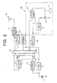
- the radio transmitter RT illustrated in Fig.2 comprises a control apparatus or a microcomputer 10 which has a power terminal 10a connected with an electric source such as a lithium cell 11 capable of applying a voltage higher than that necessary for operating the apparatus 10 via a voltage regulator 12 and an input terminal 10b for receiving an activation signal from a timer 13 consisting, for instance, of a condenser which is also connected with the cell 11 via the regulator so that the microcomputer 10 may be cyclically brought in activated and standby states at predetermined interval To e.g. of 15 seconds, as shown in Fig.5(I), so that, when necessary operations have been finished, the microcomputer is brought in a normal standby state.
- an electric source such as a lithium cell 11 capable of applying a voltage higher than that necessary for operating the apparatus 10 via a voltage regulator 12
- an input terminal 10b for receiving an activation signal from a timer 13 consisting, for instance, of a condenser which is also connected with the cell 11 via the regulator so that the microcomputer 10 may
- the microcomputer 10 has a third terminal 10c for receiving a warning signal from a detector 14 which is adapted to detect the voltage drop of the cell 11 below a rated input voltage of the voltage regulator 12 and output the warning signal.
- the microcomputer 10 is connected with a memory 15, which is always supplied with electric power from the cell 11 via the voltage regulator 12 so as to store liquid level data from means 20 for detecting liquid level.
- the level detecting means 20 comprises another voltage regulator 21 which is connected with the cell 11 via a switch 16, a potentiometer 22 to be driven for rotation depending on up-and-down movement of a float F on the liquid level so as to vary the voltage given by the regulator 21, and a voltage-frequency convertor 23 so as to output frequency signals which correspond to the varied voltages from the potentiometer 22, to be supplied to the microcomputer 10.
- means for modulation 17 connected with the electric source 11 via the voltage regulator 12 and with the microcomputer 10 via a second switch 18, which may be turned ON by a signal from the apparatus 10 so that the activated means 17 may modulate the carrier waves for transmitting the measured data as frequency signals from an antenna 19.
- Fig.3 shows an embodiment of said modulating means 17, which comprises a modulator circuit 24 for receiving liquid level data and/or voltage drop signal from the microcomputer 10 as well as carrier waves from an oscillator circuit 25 so as to transmit the corresponding frequency signals.
- the oscillator circuit is preferably connected with a band setting circuit 26 having a plurality of e.g. two switches 26a, 26b and a frequency setting circuit 27 having a plurality of e.g. three switches 27a, 27b, 27c so as to select a paticular band width in order to avoid a possible interference with neighbouring radio apparatus and a particular frequency in the selected band width in order to distinguish the signals of any one tank, e.g. tank T1 from those of the other tanks T2,T3.
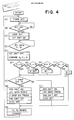
- Step A in Fig.4 when the power is supplied from the cell 11 to the microcomputer 10, this is put in the standby state where the signal for activation thereof can be received from the timer 13 and the timer 13 itself starts its operation (Step A in Fig.4).
- the timer 13 is adapted to output the activation signal (Step B in Fig.4, I in Fig.5), whereby the microcomputer 10 is put in the activated state so as to turn the first switch 16 ON so as to supply electric power from the cell 11 to the liquid level detector 20 (Step C).
- the voltage signals from the potentiometer 22, which correspond to liquid level just determined are converted to frequency signals by virtue of the convertor 23 so that the level data F1 is inputted in the microcomputer 10 (Step D)
- the first switch 16 is turned OFF so that the power supply to the level detecting means 20 is shut and the level data F0 of the last time which is stored in the memory 15 is compared with the data F1 and further with the stored lavel data F -1 of the two times earlier than that (Step E).
- Step F When now supposing that the tank is not resupplied with fresh fuel e.g. by the tank lorry, i.e. the liquid level in the tank is being lowered or not changed, the level signal transmission is conducted at long time intervals T2 as shown in Fig.5(III), and the reply to (F1>F0?) in Step F is to be N o and (F -1 ⁇ F0?) in Step G is also to be N o.
- the existing number N is decreased by one and the resultant number is memorized in the memory 15 (Step J), and the values F ⁇ 1,F0 are renewed(Step N), after which the microcomputer 10 is put in the standby state until the timer 13 gives the signal again activating thereof.
- Step N the liquid level data F -1 , F0 are renewed and the microcomputer 10 is automatically turned to be in the standby state (Step N) until the next activation signal is given from the timer.
- the microcomputer 10 is in the standby state, it consumes the electric power only a little and the modulating means 17, level measuring means 20 are kept in the passive state so as to save useless consumption of the electric source.
- Step F the liquid level is rapidly raised so that the reply in Step F is Y es.
- the reply in Step K is N o
- the second switch 18 is turned ON so as to transmit the level data and then the switch is turned OFF.
- the level data stored in the memory 15 is renewed and the computer 10 is put in the standby state.
- Step K if the reply is Y es, the voltage drop signal is transmitted in addition to the transmission of the liquid level signal.
- the transmission of the liquid level signal is made more frequently and every time when the microcomputer is energized different from the case where the liquid level is being lowered or not changed so as to relevantly comply with the rapid rise of the level for preventing the fuel from overflowing.
- the reply in Step F is N o and the reply in Step G is Y es.
- Fig.6 illustrates an embodiment of the radio receiver RR according to the invention, in which a receiver tuning circuit 40 having an antenna 41 is adapted to receive data through a plurality of channels transmitted respectively from the corresponding number of the underground tanks and to be demodulated for giving the corresponding number of outputs.
- the respective outputs on the liquid level data and the voltage drop warning signal are stored in the respective addresses in a memory 42.
- the stored informations are respectively read by a reading means of a microcomputer 43.
- the microcomputer 43 is connected with a memory for informations necessary for conversion 44 which converts data on the liquid level to those on the liquid volume based on informations stored therein in advance as to the respective tanks.
- memories 45 and 46 which are respectively connected with the microcomputer 43 and stored in advance with maximum and minimum liquid volumes in the respective tanks.
- the microcomputer 43 is connected with a transmission circuit 48 for communication, when necessary, with a point of sales (POS), and also connected with an indicator board 50 via means 47 for driving the indicators.
- POS point of sales
- the indicator board 50 has indicators 51-1, 51-2, 51-3 showing the present liquid volumes respectively in the underground tanks T1, T2, T3, indicators 52-1, 52-2, 52-3 and indicators 53-1, 53-2, 53-3 respectively for warning that the liquid volumes in the respective tanks reaches or is going to reach the maximum and minimum volumes, and indicators 54-1, 54-2, 54-3 for warning that the voltage of the cell 11 of the respective radio transmitter RT drops below the rated value.
- the board 50 may be provided further with a buzzer 55 for warning, a printer 56 for outputting the respective liquid volumes and keys 57 for setting all sorts of data in the memories in advance.
- the frequency signals transmitted by the radio transmitter RT are received by the antenna 41 and introduced into the demodulation means 40 so that the liquid level data as well as voltage drop signal when involved are stored in the respective addresses of the memory 42 and renewed every when the second signals arrive (Step A) to be read by the microcomputer 43 (Step B).
- Step C When the reply to (DATA NORMAL?) where the data involve foreign or disturbance data e.g. caused by noises is Y es (Step C), the liquid level is converted to the liquid volume based on the informations stored in the memory 44, the before-last volume data and the last volume data are renewed in the memory 42 so that the latter memorizes the last volume data A0 and the present volume data A1, and then the renewed volume data A1 is indicated (Step D).
- Step E When the above volume data A1 is compared with the volume data A0 (step E), and if the reply to (A1>A0?) is Y es where the liquid volume is being increased, a time C is set as C1 (e.g. 1 minute) (Step F) and if the reply is N o where the luquid volume is being decreased or not changed, a time C is set as C2 (e.g. 10 minutes) (Step G).
- C1 e.g. 1 minute
- Steps H,J the volume data A1 is compared with the maximum volume and the minimum volume respectively stored in the memory 45, 46.
- the reply is Y es
- the respective indicator 52, 53 of the concerned channel are energized to give warning (Steps I.K.).
- the concerned signal is stored in the corresponding addresses of the memory 42 so that, when the reply to (Voltage Signal?) is Y es (Step L), the concerned warning is indicated on the board 50 (Step M).
- Step N When it is requested from POS to transmit the data (Step N), the necessary data is sent (Step 0).
- Step Q It becomes necessary in this case to confirm whether or not the liquid level is being raised by inquiring (C1 set?) (Step Q). If the reply is Y es which means that the tank is being resupplied from the tank lorry so that level is being rapidly raised, it is necessary not only to inform the situation e.g. by printing out the concerned message by the printer 56 but also to shut a valve to the tank in order to avoid possible fuel overflow (Step R), preferably together with buzzering by the buzzer 56.
- Tank lorries are generally provided with a mechanism to stop the pump in reply to rapid rising of the pressure. If the reply is N o in Step Q, there is no necessity to take urgent countermeasure so that the situation is informed only e.g. by printing out the concerned message (Step S) preferably together with buzzering.
- the receiver RR is, however, still kept so as to give warning (Step R in Fig. 7) when no signal arrives in every one minute because the reply to (C1 set?) in Step Q (Fig.7) is still Y es .
- the number M in the memory 15 is decreased one by one in Step P in every activation of the microcomputer 10 until it comes to zero. Thereafter, the transmitter RT sends the signals in the longer transmission interval through Steps F, G, H, I.
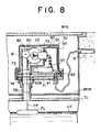
- the radio transmitter RT is preferably contained in a gas tightly sealed inner casing 60 which is covered with an outer casing 70 which is fixedly mounted in a manhole defined by an iron lid MHL which is flush with the ground level in the gasoline station, iron side walls and an iron bottom wall MHW, and arranged above the tank TL.
- the float FL is on a level LV of the liquid such as fuel to be dispensed and resupplied, and fixed with an end of an extended tape TP, the other end portion of which is wound around a drum 80, which is mounted on a bracket 81 for rotation which is mounted further with a spring 82 so as to keep the tape TP always in tension despite the up-and-down movement of the float FL.
- the assembly well known in itself is mounted on the inner casing 60 to be covered with the outer casing 70.
- the drum 80 has a shaft fixed therewith and mounted with a gear 83 so that the potentiometer 22 arranged nearby and gearingly engaged therewith may be rotated for varying voltage corresponding to varied liquid level.
- the outer casing 70 comprises a base member 71 preferably in the form of a disc and a flanged box 72 preferably in the form of a hat to be fixed with each other e.g. by a plurality of bolts 73 at the peripheral flange or the brim.
- the disc 71 is gas tightly fixed on the upper end of a vertically protruded tube TB, through which the tape TP passes, e.g. by bolts 74 and an O-ring.
- the disc 71 is naturally formed with a hole for the tape to pass therethrough.
- the inner casing 60 comprises a base member 61 preferably in the form of a disc and a flanged box 62 preferably in the form of a hat to be gas-tightly engaged with each other at the peripheral flange or the brim e.g. by a plurality of bolts 63.
- the hat-like box 62 is partly cut off and partly stopped so as to form a low flat portion 62A where a hole is correspondingly formed for the tape TP and a higher stepped portion 62 B on which a vertical wall 62C of the flanged box 62 stands.
- the wall 62C is formed with a hole in which the potentimeter 22 is gas-tightly inserted e.g.
- the drum assembly is mounted on the flat portion 62A to be readily removed so that the drum 80, around which the tape TP passing the hole, may be positioned above the stepped portion 62B and so that the gear 83 of the drum 80 may drivingly engage with the potentiometer shaft mounted with a gear.
- the inner base member 61 carries the radio transmitter RT fixedly and the cell or cells 11 removably thereon, the latter of which is electrically connected with the former for supplying electric power.
- the radio transmitter RT is electrically connected further with the potentiometer so as to convert the varied voltages to the frequency signals to be transmitted through the antenna 19, which is preferably positioned in a groove formed in the earth outside of the tank and connected with the RT by a sheathed wire.
- the manhole lid of the underground tank in question is lifted up, the bolts 73 are disengaged and the uppermost flanged box 72 is brought up, whereby the gas-tightly sealed casing 60 containing the cell as well as electronic elements may be removed from the lowermost base member 71.
- the casing 60 is brought to any place where exchange of the cell can be made without a fear of explosion e.g. in the office cabin, together with the tape and float or after the drum assembly is removed together with the tape and the float from the casing.
Landscapes
- Physics & Mathematics (AREA)
- Fluid Mechanics (AREA)
- General Physics & Mathematics (AREA)
- Engineering & Computer Science (AREA)
- Signal Processing (AREA)
- Arrangements For Transmission Of Measured Signals (AREA)
- Transmitters (AREA)
- Measurement Of Levels Of Liquids Or Fluent Solid Materials (AREA)
Applications Claiming Priority (4)
| Application Number | Priority Date | Filing Date | Title |
|---|---|---|---|
| JP329586/88 | 1988-12-26 | ||
| JP63329586A JP2784021B2 (ja) | 1988-12-26 | 1988-12-26 | 無線式液量測定装置 |
| JP61314/89 | 1989-03-13 | ||
| JP1061314A JP2552639B2 (ja) | 1989-03-13 | 1989-03-13 | 無線式液位測定装置 |
Publications (3)
| Publication Number | Publication Date |
|---|---|
| EP0376646A2 true EP0376646A2 (fr) | 1990-07-04 |
| EP0376646A3 EP0376646A3 (fr) | 1990-08-29 |
| EP0376646B1 EP0376646B1 (fr) | 1998-05-06 |
Family
ID=26402355
Family Applications (1)
| Application Number | Title | Priority Date | Filing Date |
|---|---|---|---|
| EP89313512A Expired - Lifetime EP0376646B1 (fr) | 1988-12-26 | 1989-12-22 | Système pour la radiotransmission des indications du niveau d'un liquide et pour la conversion des indications reçues en indications de volume pour l'affichage |
Country Status (8)
| Country | Link |
|---|---|
| US (1) | US5111201A (fr) |
| EP (1) | EP0376646B1 (fr) |
| KR (1) | KR930001723B1 (fr) |
| AU (1) | AU632779B2 (fr) |
| DE (1) | DE68928664T2 (fr) |
| DK (1) | DK658389A (fr) |
| ES (1) | ES2119736T3 (fr) |
| MY (1) | MY106078A (fr) |
Cited By (18)
| Publication number | Priority date | Publication date | Assignee | Title |
|---|---|---|---|---|
| EP0473366A1 (fr) * | 1990-08-24 | 1992-03-04 | Louis J. Jannotta | Système de jaugeage du niveau de liquide |
| FR2669421A1 (fr) * | 1990-11-20 | 1992-05-22 | Gaudriot Cabinet Etudes | Procede et dispositif d'enregistrement de parametres pour une canalisation dans laquelle circule un fluide. |
| EP0626569A1 (fr) * | 1993-05-22 | 1994-11-30 | KRONE Aktiengesellschaft | Procédé de surveillance de niveau du contenu dans des réservoirs |
| ES2079285A2 (es) * | 1993-09-28 | 1996-01-01 | Repsol Butano Sa | Sistema de telemedida de gases licuados de petroleo. |
| EP0626568A3 (fr) * | 1993-05-28 | 1996-01-31 | Simmonds Precision Products | Jauge de liquide et capteur à interrogation à distance. |
| GB2294546A (en) * | 1994-10-26 | 1996-05-01 | Scully Uk Ltd | Fluid level detector |
| EP0710820A1 (fr) * | 1994-10-26 | 1996-05-08 | Scully Uk Limited | Détecteur de niveau d'un fluide et rapporteur de niveau d'un liquide |
| US5627380A (en) * | 1993-05-28 | 1997-05-06 | Simmonds Precision Products, Inc. | Fluid gauging apparatus using integral electrical sensor and a stick gauge |
| DE29709023U1 (de) * | 1997-05-20 | 1997-10-09 | Fernmeldebau Schwarzheide GmbH, 01987 Schwarzheide | Vorrichtung für die Meldung von Pegel- und Betriebszuständen |
| US5723870A (en) * | 1993-05-28 | 1998-03-03 | Simmonds Precision Products Inc. | Fluid gauging apparatus using magnetostrictive sensor and stick gauge |
| US5814830A (en) * | 1994-10-18 | 1998-09-29 | Simmonds Precision Products, Inc. | Liquid gauging apparatus with a magnetoresistive sensor and remote sensor interrogration |
| EP1045228A1 (fr) * | 1999-04-12 | 2000-10-18 | Imatel Sistemas s.l. | Système mesurant le taux de remplissage de réservoirs par l'intermédiaire d'un émeteur/récepteur de données brèves par ondes radio à courtes ou longes distances |
| WO2005073891A3 (fr) * | 2004-01-16 | 2006-01-05 | Lpg Central Inc | Systeme et procede de telesurveillance d'equipements |
| EP1944825A1 (fr) * | 2007-01-10 | 2008-07-16 | Enegene Co., Ltd. | Dispositif de radio enfouie |
| CN100481145C (zh) * | 2004-01-16 | 2009-04-22 | 全球遥测技术公司 | 用于远程资产监视的系统和方法 |
| WO2009053706A3 (fr) * | 2007-10-26 | 2009-07-09 | Jenny Maxwell | Appareil de détection de liquide |
| EP2131164A1 (fr) | 2008-06-06 | 2009-12-09 | Tekelek Patents Limited | Procédé et appareil pour déterminer le niveau de matériau dans un conteneur |
| US11976955B2 (en) | 2018-09-21 | 2024-05-07 | Ecolab Usa Inc. | Portable fluid level monitoring device and method |
Families Citing this family (14)
| Publication number | Priority date | Publication date | Assignee | Title |
|---|---|---|---|---|
| US5226313A (en) * | 1989-12-15 | 1993-07-13 | Murata Mfg. Co., Ltd. | Body fluid excretion measurement apparatus for medical application |
| JP2806589B2 (ja) * | 1990-01-23 | 1998-09-30 | 日本電気株式会社 | 移動電話装置 |
| JP3273052B2 (ja) * | 1991-01-29 | 2002-04-08 | シーティーエス・コーポレーション | 位置センサと共にパッケージ化された電子回路 |
| US5714681A (en) * | 1996-05-14 | 1998-02-03 | Furness; Robert L. | Double carcass hose failure detection system |
| US6336362B1 (en) | 1998-01-22 | 2002-01-08 | Roy A. Duenas | Method and system for measuring and remotely reporting the liquid level of tanks and the usage thereof |
| US6685296B2 (en) * | 2000-06-16 | 2004-02-03 | Canon Kabushiki Kaisha | Ink tank and ink jet recording apparatus provided with the same |
| US6742396B2 (en) | 2001-04-07 | 2004-06-01 | Robertshaw Controls Company | Method for upgrading a dial indicator to provide remote indication capability |
| US20030010115A1 (en) * | 2001-07-16 | 2003-01-16 | Kelley Ronald J. | Means for measuring the liquid level in a reservoir for a fuel cell |
| US7002481B1 (en) * | 2002-03-05 | 2006-02-21 | Aeromesh Corporation | Monitoring system and method |
| US7626508B2 (en) * | 2002-03-05 | 2009-12-01 | Aeromesh Corporation | Monitoring system and method |
| US7788048B2 (en) * | 2003-04-24 | 2010-08-31 | Hewlett-Packard Development Company, L.P. | Apparatus and method for integrating a fuel supply and a fuel level sensing pressure sensor |
| US8447367B2 (en) * | 2007-05-07 | 2013-05-21 | Rosemount Tank Radar Ab | Process measurement instrument adapted for wireless communication |
| US9035822B2 (en) * | 2012-06-18 | 2015-05-19 | Rosemount Tank Radar Ab | Intermittent filling level determination with dynamically determined number of measurements |
| US8970395B2 (en) | 2012-06-29 | 2015-03-03 | Rosemount Tank Radar Ab | Battery-powered level gauge system adapted for wireless communication |
Family Cites Families (14)
| Publication number | Priority date | Publication date | Assignee | Title |
|---|---|---|---|---|
| US2588102A (en) * | 1948-10-22 | 1952-03-04 | Francisco A Forero | Liquid level signaling apparatus |
| US3681753A (en) * | 1970-08-05 | 1972-08-01 | George J Whalen | Electronic fuel level warning device |
| US3983750A (en) * | 1975-09-29 | 1976-10-05 | The United States Of America As Represented By The Secretary Of The Navy | Fluid level sensing device |
| US4094437A (en) * | 1976-08-30 | 1978-06-13 | Tokico Ltd. | Cap assembly and method for producing thereof |
| IT1131315B (it) * | 1980-06-13 | 1986-06-18 | Logic Spa | Sistema di rilevamento e segnalazione della quantita' di carburante contenuto in un serbatoio di veicoli,particolarmente di veicoli aerei |
| US4399440A (en) * | 1981-02-17 | 1983-08-16 | Sparton Corporation | Addressable transducer with a variable frequency oscillation for monitoring a physical quantity |
| US4459584A (en) * | 1981-12-21 | 1984-07-10 | Clarkson Marvin R | Automatic liquid level indicator and alarm system |
| US4449248A (en) * | 1982-02-01 | 1984-05-15 | General Electric Company | Battery saving radio circuit and system |
| US4513617A (en) * | 1983-01-03 | 1985-04-30 | Mitch's Self Service Gas, Inc. | Storage tank gauging measuring apparatus |
| US4571998A (en) * | 1984-07-18 | 1986-02-25 | Kevin Stegner | In-ground tank measuring system |
| GB8423369D0 (en) * | 1984-09-15 | 1984-10-17 | Snell J D | Monitoring of liquids |
| JPS62128228A (ja) * | 1985-11-28 | 1987-06-10 | Hitachi Ltd | 間欠受信方式 |
| US4716463A (en) * | 1986-10-24 | 1987-12-29 | Zenith Electronics Corporation | Power down sense circuit |
| US4924221A (en) * | 1988-12-05 | 1990-05-08 | Andrew Filippone | Remote oil tank display apparatus |
-
1989
- 1989-12-22 MY MYPI89001849A patent/MY106078A/en unknown
- 1989-12-22 ES ES89313512T patent/ES2119736T3/es not_active Expired - Lifetime
- 1989-12-22 DK DK658389A patent/DK658389A/da not_active Application Discontinuation
- 1989-12-22 DE DE68928664T patent/DE68928664T2/de not_active Expired - Fee Related
- 1989-12-22 AU AU47234/89A patent/AU632779B2/en not_active Ceased
- 1989-12-22 EP EP89313512A patent/EP0376646B1/fr not_active Expired - Lifetime
- 1989-12-23 KR KR1019890019374A patent/KR930001723B1/ko not_active Expired - Fee Related
- 1989-12-26 US US07/456,912 patent/US5111201A/en not_active Expired - Fee Related
Cited By (20)
| Publication number | Priority date | Publication date | Assignee | Title |
|---|---|---|---|---|
| EP0473366A1 (fr) * | 1990-08-24 | 1992-03-04 | Louis J. Jannotta | Système de jaugeage du niveau de liquide |
| FR2669421A1 (fr) * | 1990-11-20 | 1992-05-22 | Gaudriot Cabinet Etudes | Procede et dispositif d'enregistrement de parametres pour une canalisation dans laquelle circule un fluide. |
| EP0626569A1 (fr) * | 1993-05-22 | 1994-11-30 | KRONE Aktiengesellschaft | Procédé de surveillance de niveau du contenu dans des réservoirs |
| US5723870A (en) * | 1993-05-28 | 1998-03-03 | Simmonds Precision Products Inc. | Fluid gauging apparatus using magnetostrictive sensor and stick gauge |
| EP0626568A3 (fr) * | 1993-05-28 | 1996-01-31 | Simmonds Precision Products | Jauge de liquide et capteur à interrogation à distance. |
| US5530258A (en) * | 1993-05-28 | 1996-06-25 | Simmonds Precision Products, Inc. | Liquid gauging apparatus and remote sensor interrogation |
| US5627380A (en) * | 1993-05-28 | 1997-05-06 | Simmonds Precision Products, Inc. | Fluid gauging apparatus using integral electrical sensor and a stick gauge |
| ES2079285A2 (es) * | 1993-09-28 | 1996-01-01 | Repsol Butano Sa | Sistema de telemedida de gases licuados de petroleo. |
| US5814830A (en) * | 1994-10-18 | 1998-09-29 | Simmonds Precision Products, Inc. | Liquid gauging apparatus with a magnetoresistive sensor and remote sensor interrogration |
| GB2294546A (en) * | 1994-10-26 | 1996-05-01 | Scully Uk Ltd | Fluid level detector |
| EP0710820A1 (fr) * | 1994-10-26 | 1996-05-08 | Scully Uk Limited | Détecteur de niveau d'un fluide et rapporteur de niveau d'un liquide |
| DE29709023U1 (de) * | 1997-05-20 | 1997-10-09 | Fernmeldebau Schwarzheide GmbH, 01987 Schwarzheide | Vorrichtung für die Meldung von Pegel- und Betriebszuständen |
| EP1045228A1 (fr) * | 1999-04-12 | 2000-10-18 | Imatel Sistemas s.l. | Système mesurant le taux de remplissage de réservoirs par l'intermédiaire d'un émeteur/récepteur de données brèves par ondes radio à courtes ou longes distances |
| WO2005073891A3 (fr) * | 2004-01-16 | 2006-01-05 | Lpg Central Inc | Systeme et procede de telesurveillance d'equipements |
| US7337078B2 (en) | 2004-01-16 | 2008-02-26 | Worldtelemetry, Inc. | System and method for remote asset monitoring |
| CN100481145C (zh) * | 2004-01-16 | 2009-04-22 | 全球遥测技术公司 | 用于远程资产监视的系统和方法 |
| EP1944825A1 (fr) * | 2007-01-10 | 2008-07-16 | Enegene Co., Ltd. | Dispositif de radio enfouie |
| WO2009053706A3 (fr) * | 2007-10-26 | 2009-07-09 | Jenny Maxwell | Appareil de détection de liquide |
| EP2131164A1 (fr) | 2008-06-06 | 2009-12-09 | Tekelek Patents Limited | Procédé et appareil pour déterminer le niveau de matériau dans un conteneur |
| US11976955B2 (en) | 2018-09-21 | 2024-05-07 | Ecolab Usa Inc. | Portable fluid level monitoring device and method |
Also Published As
| Publication number | Publication date |
|---|---|
| EP0376646B1 (fr) | 1998-05-06 |
| US5111201A (en) | 1992-05-05 |
| DE68928664T2 (de) | 1999-02-11 |
| EP0376646A3 (fr) | 1990-08-29 |
| DE68928664D1 (de) | 1998-06-10 |
| MY106078A (en) | 1995-03-31 |
| DK658389A (da) | 1990-06-27 |
| DK658389D0 (da) | 1989-12-22 |
| AU4723489A (en) | 1990-06-28 |
| KR900010360A (ko) | 1990-07-07 |
| AU632779B2 (en) | 1993-01-14 |
| KR930001723B1 (ko) | 1993-03-12 |
| ES2119736T3 (es) | 1998-10-16 |
Similar Documents
| Publication | Publication Date | Title |
|---|---|---|
| US5111201A (en) | System radio transmission of liquid level data and battery saving technique | |
| US4782451A (en) | Process for maintaining liquid supply | |
| US5211678A (en) | Apparatus, method and system for monitoring fluid | |
| US5708424A (en) | Wireless remote fuel gauge | |
| US4263945A (en) | Automatic fuel dispensing control system | |
| US5261276A (en) | Fuel oil monitor system and method | |
| EP2131164B1 (fr) | Procédé et appareil pour déterminer le niveau de matériau dans un conteneur | |
| US7441569B2 (en) | Will call wireless tank level monitoring system | |
| US4236144A (en) | Inspection system for a group of tanks | |
| US5272920A (en) | Apparatus, method and system for monitoring fluid | |
| JP3082783B2 (ja) | 無線式液量測定装置 | |
| EP1045228A1 (fr) | Système mesurant le taux de remplissage de réservoirs par l'intermédiaire d'un émeteur/récepteur de données brèves par ondes radio à courtes ou longes distances | |
| JP2788318B2 (ja) | 無線式液量測定装置 | |
| JP2784021B2 (ja) | 無線式液量測定装置 | |
| JP2552639B2 (ja) | 無線式液位測定装置 | |
| KR0126416B1 (ko) | 액량측정장치 | |
| JPH0812100B2 (ja) | 液面測定装置 | |
| JPH02176425A (ja) | 無線式液位信号送信装置 | |
| GB2271855A (en) | Replenishment system | |
| TH8023B (th) | ระบบสำหรับส่งสัญญาณวิทยุเกี่ยวกับข้อมูลแสดงระดับของเหลว และสำหรับแปลงข้อมูลที่ได้รับเป็นข้อมูลแสดงปริมาตร | |
| JP3072654B2 (ja) | フロート式液位測定装置 | |
| US7398188B2 (en) | Apparatus for determining and/or monitoring a physical or chemical quantity | |
| US6216623B1 (en) | Tanker void space leakage detector system | |
| GB1575548A (en) | Monitoring of the contents of a container | |
| TH18356A (th) | ระบบสำหรับส่งสัญญาณวิทยุเกี่ยวกับข้อมูลแสดงระดับของเหลว และสำหรับแปลงข้อมูลที่ได้รับเป็นข้อมูลแสดงปริมาตร |
Legal Events
| Date | Code | Title | Description |
|---|---|---|---|
| PUAI | Public reference made under article 153(3) epc to a published international application that has entered the european phase |
Free format text: ORIGINAL CODE: 0009012 |
|
| AK | Designated contracting states |
Kind code of ref document: A2 Designated state(s): DE ES GB IT NL SE |
|
| PUAL | Search report despatched |
Free format text: ORIGINAL CODE: 0009013 |
|
| RHK1 | Main classification (correction) |
Ipc: G08C 17/00 |
|
| AK | Designated contracting states |
Kind code of ref document: A3 Designated state(s): DE ES GB IT NL SE |
|
| 17P | Request for examination filed |
Effective date: 19901129 |
|
| 17Q | First examination report despatched |
Effective date: 19930210 |
|
| GRAG | Despatch of communication of intention to grant |
Free format text: ORIGINAL CODE: EPIDOS AGRA |
|
| GRAG | Despatch of communication of intention to grant |
Free format text: ORIGINAL CODE: EPIDOS AGRA |
|
| GRAH | Despatch of communication of intention to grant a patent |
Free format text: ORIGINAL CODE: EPIDOS IGRA |
|
| GRAH | Despatch of communication of intention to grant a patent |
Free format text: ORIGINAL CODE: EPIDOS IGRA |
|
| GRAH | Despatch of communication of intention to grant a patent |
Free format text: ORIGINAL CODE: EPIDOS IGRA |
|
| GRAA | (expected) grant |
Free format text: ORIGINAL CODE: 0009210 |
|
| AK | Designated contracting states |
Kind code of ref document: B1 Designated state(s): DE ES GB IT NL SE |
|
| REF | Corresponds to: |
Ref document number: 68928664 Country of ref document: DE Date of ref document: 19980610 |
|
| ITF | It: translation for a ep patent filed | ||
| REG | Reference to a national code |
Ref country code: ES Ref legal event code: FG2A Ref document number: 2119736 Country of ref document: ES Kind code of ref document: T3 |
|
| NLT1 | Nl: modifications of names registered in virtue of documents presented to the patent office pursuant to art. 16 a, paragraph 1 |
Owner name: TATSUNO CORPORATION |
|
| PLBE | No opposition filed within time limit |
Free format text: ORIGINAL CODE: 0009261 |
|
| STAA | Information on the status of an ep patent application or granted ep patent |
Free format text: STATUS: NO OPPOSITION FILED WITHIN TIME LIMIT |
|
| REG | Reference to a national code |
Ref country code: ES Ref legal event code: PC2A |
|
| 26N | No opposition filed | ||
| PGFP | Annual fee paid to national office [announced via postgrant information from national office to epo] |
Ref country code: GB Payment date: 19991112 Year of fee payment: 11 |
|
| PGFP | Annual fee paid to national office [announced via postgrant information from national office to epo] |
Ref country code: SE Payment date: 19991122 Year of fee payment: 11 |
|
| PGFP | Annual fee paid to national office [announced via postgrant information from national office to epo] |
Ref country code: ES Payment date: 19991228 Year of fee payment: 11 |
|
| PGFP | Annual fee paid to national office [announced via postgrant information from national office to epo] |
Ref country code: NL Payment date: 19991231 Year of fee payment: 11 |
|
| PGFP | Annual fee paid to national office [announced via postgrant information from national office to epo] |
Ref country code: DE Payment date: 20000103 Year of fee payment: 11 |
|
| PG25 | Lapsed in a contracting state [announced via postgrant information from national office to epo] |
Ref country code: GB Free format text: LAPSE BECAUSE OF NON-PAYMENT OF DUE FEES Effective date: 20001222 |
|
| PG25 | Lapsed in a contracting state [announced via postgrant information from national office to epo] |
Ref country code: SE Free format text: LAPSE BECAUSE OF NON-PAYMENT OF DUE FEES Effective date: 20001223 |
|
| PG25 | Lapsed in a contracting state [announced via postgrant information from national office to epo] |
Ref country code: NL Free format text: LAPSE BECAUSE OF NON-PAYMENT OF DUE FEES Effective date: 20010701 |
|
| EUG | Se: european patent has lapsed |
Ref document number: 89313512.9 |
|
| GBPC | Gb: european patent ceased through non-payment of renewal fee |
Effective date: 20001222 |
|
| NLV4 | Nl: lapsed or anulled due to non-payment of the annual fee |
Effective date: 20010701 |
|
| PG25 | Lapsed in a contracting state [announced via postgrant information from national office to epo] |
Ref country code: DE Free format text: LAPSE BECAUSE OF NON-PAYMENT OF DUE FEES Effective date: 20011002 |
|
| PG25 | Lapsed in a contracting state [announced via postgrant information from national office to epo] |
Ref country code: ES Free format text: LAPSE BECAUSE OF NON-PAYMENT OF DUE FEES Effective date: 20011223 |
|
| REG | Reference to a national code |
Ref country code: ES Ref legal event code: FD2A Effective date: 20020112 |
|
| PG25 | Lapsed in a contracting state [announced via postgrant information from national office to epo] |
Ref country code: IT Free format text: LAPSE BECAUSE OF NON-PAYMENT OF DUE FEES;WARNING: LAPSES OF ITALIAN PATENTS WITH EFFECTIVE DATE BEFORE 2007 MAY HAVE OCCURRED AT ANY TIME BEFORE 2007. THE CORRECT EFFECTIVE DATE MAY BE DIFFERENT FROM THE ONE RECORDED. Effective date: 20051222 |