EP0376649A2 - Système de blocage pour vaporisateur anesthésique et connexion pour appareil d'anesthésie - Google Patents
Système de blocage pour vaporisateur anesthésique et connexion pour appareil d'anesthésie Download PDFInfo
- Publication number
- EP0376649A2 EP0376649A2 EP89313517A EP89313517A EP0376649A2 EP 0376649 A2 EP0376649 A2 EP 0376649A2 EP 89313517 A EP89313517 A EP 89313517A EP 89313517 A EP89313517 A EP 89313517A EP 0376649 A2 EP0376649 A2 EP 0376649A2
- Authority
- EP
- European Patent Office
- Prior art keywords
- vaporiser
- interlock
- crank
- adjacent
- vaporizer
- Prior art date
- Legal status (The legal status is an assumption and is not a legal conclusion. Google has not performed a legal analysis and makes no representation as to the accuracy of the status listed.)
- Withdrawn
Links
- 230000003444 anaesthetic effect Effects 0.000 title claims abstract description 33
- 239000006200 vaporizer Substances 0.000 title abstract description 84
- 206010002091 Anaesthesia Diseases 0.000 claims abstract description 18
- 230000037005 anaesthesia Effects 0.000 claims abstract description 18
- 239000007789 gas Substances 0.000 claims description 29
- 230000033001 locomotion Effects 0.000 claims description 18
- 239000012159 carrier gas Substances 0.000 claims description 10
- 230000002093 peripheral effect Effects 0.000 claims description 2
- 238000001949 anaesthesia Methods 0.000 abstract description 17
- 230000007246 mechanism Effects 0.000 description 6
- 230000029058 respiratory gaseous exchange Effects 0.000 description 6
- 229940124326 anaesthetic agent Drugs 0.000 description 5
- 239000003193 general anesthetic agent Substances 0.000 description 5
- 239000002184 metal Substances 0.000 description 5
- GQPLMRYTRLFLPF-UHFFFAOYSA-N Nitrous Oxide Chemical compound [O-][N+]#N GQPLMRYTRLFLPF-UHFFFAOYSA-N 0.000 description 4
- 230000004913 activation Effects 0.000 description 3
- 238000001994 activation Methods 0.000 description 3
- 239000003570 air Substances 0.000 description 2
- QVGXLLKOCUKJST-UHFFFAOYSA-N atomic oxygen Chemical compound [O] QVGXLLKOCUKJST-UHFFFAOYSA-N 0.000 description 2
- 238000010276 construction Methods 0.000 description 2
- 239000007788 liquid Substances 0.000 description 2
- 229960001730 nitrous oxide Drugs 0.000 description 2
- 239000001272 nitrous oxide Substances 0.000 description 2
- 239000001301 oxygen Substances 0.000 description 2
- 229910052760 oxygen Inorganic materials 0.000 description 2
- PIWKPBJCKXDKJR-UHFFFAOYSA-N Isoflurane Chemical compound FC(F)OC(Cl)C(F)(F)F PIWKPBJCKXDKJR-UHFFFAOYSA-N 0.000 description 1
- 230000009471 action Effects 0.000 description 1
- 230000008901 benefit Effects 0.000 description 1
- 230000000694 effects Effects 0.000 description 1
- 230000005611 electricity Effects 0.000 description 1
- 229960003132 halothane Drugs 0.000 description 1
- BCQZXOMGPXTTIC-UHFFFAOYSA-N halothane Chemical compound FC(F)(F)C(Cl)Br BCQZXOMGPXTTIC-UHFFFAOYSA-N 0.000 description 1
- 230000003455 independent Effects 0.000 description 1
- 230000037431 insertion Effects 0.000 description 1
- 238000003780 insertion Methods 0.000 description 1
- 230000003993 interaction Effects 0.000 description 1
- 229960002725 isoflurane Drugs 0.000 description 1
- 239000000463 material Substances 0.000 description 1
- 229940075473 medical gases Drugs 0.000 description 1
- 230000001105 regulatory effect Effects 0.000 description 1
- 229920006395 saturated elastomer Polymers 0.000 description 1
- 238000007789 sealing Methods 0.000 description 1
- 125000006850 spacer group Chemical group 0.000 description 1
- 229910001220 stainless steel Inorganic materials 0.000 description 1
- 239000010935 stainless steel Substances 0.000 description 1
- 230000003068 static effect Effects 0.000 description 1
- 238000009834 vaporization Methods 0.000 description 1
- 230000008016 vaporization Effects 0.000 description 1
Images




Classifications
-
- A—HUMAN NECESSITIES
- A61—MEDICAL OR VETERINARY SCIENCE; HYGIENE
- A61M—DEVICES FOR INTRODUCING MEDIA INTO, OR ONTO, THE BODY; DEVICES FOR TRANSDUCING BODY MEDIA OR FOR TAKING MEDIA FROM THE BODY; DEVICES FOR PRODUCING OR ENDING SLEEP OR STUPOR
- A61M16/00—Devices for influencing the respiratory system of patients by gas treatment, e.g. ventilators; Tracheal tubes
- A61M16/10—Preparation of respiratory gases or vapours
- A61M16/14—Preparation of respiratory gases or vapours by mixing different fluids, one of them being in a liquid phase
- A61M16/18—Vaporising devices for anaesthetic preparations
- A61M16/186—Locking systems
-
- Y—GENERAL TAGGING OF NEW TECHNOLOGICAL DEVELOPMENTS; GENERAL TAGGING OF CROSS-SECTIONAL TECHNOLOGIES SPANNING OVER SEVERAL SECTIONS OF THE IPC; TECHNICAL SUBJECTS COVERED BY FORMER USPC CROSS-REFERENCE ART COLLECTIONS [XRACs] AND DIGESTS
- Y10—TECHNICAL SUBJECTS COVERED BY FORMER USPC
- Y10T—TECHNICAL SUBJECTS COVERED BY FORMER US CLASSIFICATION
- Y10T137/00—Fluid handling
- Y10T137/8593—Systems
- Y10T137/87096—Valves with separate, correlated, actuators
- Y10T137/87113—Interlocked
-
- Y—GENERAL TAGGING OF NEW TECHNOLOGICAL DEVELOPMENTS; GENERAL TAGGING OF CROSS-SECTIONAL TECHNOLOGIES SPANNING OVER SEVERAL SECTIONS OF THE IPC; TECHNICAL SUBJECTS COVERED BY FORMER USPC CROSS-REFERENCE ART COLLECTIONS [XRACs] AND DIGESTS
- Y10—TECHNICAL SUBJECTS COVERED BY FORMER USPC
- Y10T—TECHNICAL SUBJECTS COVERED BY FORMER US CLASSIFICATION
- Y10T74/00—Machine element or mechanism
- Y10T74/20—Control lever and linkage systems
- Y10T74/20207—Multiple controlling elements for single controlled element
- Y10T74/20238—Interlocked
-
- Y—GENERAL TAGGING OF NEW TECHNOLOGICAL DEVELOPMENTS; GENERAL TAGGING OF CROSS-SECTIONAL TECHNOLOGIES SPANNING OVER SEVERAL SECTIONS OF THE IPC; TECHNICAL SUBJECTS COVERED BY FORMER USPC CROSS-REFERENCE ART COLLECTIONS [XRACs] AND DIGESTS
- Y10—TECHNICAL SUBJECTS COVERED BY FORMER USPC
- Y10T—TECHNICAL SUBJECTS COVERED BY FORMER US CLASSIFICATION
- Y10T74/00—Machine element or mechanism
- Y10T74/20—Control lever and linkage systems
- Y10T74/20207—Multiple controlling elements for single controlled element
- Y10T74/20238—Interlocked
- Y10T74/2025—Rod blocks actuation of rotary member
Definitions
- the invention relates to anaesthesia machines and more particularly to interlock devices for anaesthesia machine vaporizers and locking devices for connecting tubing to an anaesthesia machine.
- Anaesthesia equipment typically consists of a trolley on which are mounted cylinders containing medical gases such as oxygen, air and nitrous-oxide and associated pressure regulating valves.
- Anaesthetic agents such as halothane and isoflurane are commonly administered by passing a carrier gas such as air or oxygen mixed with nitrous-oxide through a vaporizer which contains the liquid anaesthetic agent.
- Conventional anaesthesia apparatus or machines commonly incorporate two or more separate vaporizers. Each vaporizer is arranged to dispense a metered amount of anaesthesia vapor into the patient breathing circuit or fresh gas line. These vaporizers may contain differ lengthyent anaesthetic agents so that the same equipment can be used for a series of surgical operations to supply the particular anaesthetic agent desired. The arrangement of more than one vaporizer on the same anaesthetic equipment does, however, lead to the possible risk that more than one vaporizer could accidentally be connected to the gas administration circuit at the same time. In order to cope with this problem, various interlock systems have been proposed in order to prevent more than one vaporizer being operated at the same time. For example, U.K.
- patent specifications Nos. 2052271 and 2193642 describe one such interlock system. While the interlock arrangements described in these two patent specifications are satisfactory with the type of "plug-in" vaporizers described in U.K. patent specification 1385670, there is at least one other widely used system in use for connecting vaporizer units to a gas administration circuit. There is, therefore, a need for a vaporizer interlock system which can be adapted for use with more than one type of gas administration system.
- vaporizer While the construction of commercially available vaporizers varies from manufacturer to manufacturer, the most common type of vaporizer comprises a canister including a reservoir of the anaesthesia, valve means and a rotatable dial coupled to the valve means for adjusting the valve means to establish the vaporizer concentration levels.
- Such machines may include a rotary dial for adjusting the opening of a valve in the vaporizer to divide the gas flow in the vaporizer in accordance with the dial setting. Part of the gas flow passes through a by-pass, without entering the vaporizer chamber (where the anaesthetic is located), while the remaining portion of the gas flow passes through the vaporizer chamber for saturation by anaesthesia vapor.
- the gas flow which is saturated with the vapor is then combined with the by-pass gas flow so that the gas leaves the vaporizer carrying a set concentration of anaesthesia.
- the introduction of the gas carrying anaesthesia vapor into the fresh gas line is effected by an outlet valve under the control of a separate on/off switch.
- a pair of rotary cams and a pivoting lever are provided to serve as an interlock to insure that the outlet of the vaporizer is opened when the rotary dial is adjusted to any particular setting and to prevent the adjustment dial from being rotated to any setting when the on/off switch is closed, thereby precluding any gas from passing into the vaporization chamber when the outlet of the vaporizer is closed.
- the present invention also relates to a safety lock hose connector for use with the anaesthetic apparatus of the invention.
- Typical hose connectors for anaesthetic breathing systems for example, comprise a tapered, hollow male member for insertion into a correspondingly internally tapered female member. The size and degree of taper of such connectors are covered by various national and international standards.
- the male member is made of metal (generally stainless steel) and the female member is made of metal or of plastic material or, as described in GB-A-1396096, may comprise a metal sleeve housed within a plastic housing.
- the invention comprises an interlock system for use with a plurality of vaporizers which, on activation of one of the vaporizers, prevents activation of any number of vaporizers to the right or the left of the activated vaporizer.
- the invention also provides a hose connector comprising an externally tapered male connection member and an internally tapered, generally tubular, female connection member in which the male member is provided with a collar which defines, together with the male member, an annular recess for reception of the end of the female member, and the inner wall of the collar defining the recess has at least one helical groove extending from the free end of the collar towards the fixed end thereof: and the female member is provided with one or more external lugs or pins for engaging with the groove in the collar.
- the invention also provides an anaesthetic apparatus in which hose is connected to the apparatus by means of the connector of the invention.
- An anaesthesia machine having a plurality of vaporizers for introducing a metered concentration of vapor into a gas flow when opened is provided, each said vaporizer comprises rotatable adjustment cam means for opening the vaporizer, establishing the vapor concentration introduced thereby.
- an improved interlock device which prevents activation of the vaporizer when another of the vaporizers is activated.
- the interlock device comprises a cam follower which engages a notch in the rotatable adjustment cam, said cam follower comprising one end of a substantially Z shaped (first) sprung crank which is rotatable about a first fixed pin, the distal end of said sprung crank being engaged in a slot in a first sliding bar; a second substantially T shaped crank having a first end impinging on said sprung crank which is rotatable about a second fixed pin, the distal end of said second crank being engaged in a slot in a second sliding bar; said first and second sliding bars having inboard ends which have abutting contact with each other when the vaporizer is inactivated, and outboard ends which may have abutting contact with the outboard ends of a similar sliding bar on adjacent vaporizers.
- cam followers by action with the cranks and the sliding bars cooperate with each other so that when the adjustment cam means of the vaporizers are closed, one of the cam followers can be moved out of engagement with its associated notch by the mere rotation of its associated adjustment cam means to open the vaporizer and establish any vapor concentration, while such rotation locks all the other cam followers in position in engagement with its associated notch to lock its associated adjustment cam means closed.
- the invention also provides means for mounting the interlock device on the apparatus. Accordingly, the interlock device is demountable and may be easily installed on existing anaesthetic apparatus.
- the vaporizer body is preferably provided with a platform portion which is adapted to receive a mounting block for connection to the gas supply circuit. Ports are provided in the platform for connection with the interior of the vaporizer and for sealing the ports to corresponding ports in the mounting block.
- the mounting block may be a unit which is adapted to plug into a gas supply bar in a similar way to that described in U.K. Patent specification 1385670.
- the mounting block may incorporate conventional taper tubular connector parts so that the vaporizer may be connected directly to a gas supply circuit.
- the quick connect locking connector comprises a male tapered connector having an attached split collar attached to said apparatus, and a bayonet type female locking connector attached to said breathing tube, said female connector having a locking ring adapted to engage said split collar, said female connector having at least one lug affixed to its outer circumference adjacent to the connector mouth, said split collar having at least one locking groove at a precise angle and dimensions suitable to accommodate at least one lug on said female connector.
- the split collar is adapted to be easily attached to existing anaesthetic apparatus.
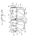
- FIG. 1 an anaesthesia machine 10 of the invention is illustrated having two vaporizers 12.
- vaporizers 12 With reference now to FIG 2, the relationship of vaporizers 12 is illustrated in an embodiment where more than two vaporizers are used.
- tubular ports 4a and 4b are upstanding on the gas supply bar 84 and are received in corresponding recesses in a housing 5.
- the vaporizers may be locked in position on the supply bar 84 by rotating the knob 6 to the position shown in the left-hand vaporizer.
- Carrier gas can be admitted into the vaporizers by rotating the cam dial 22 of the vaporizers whereupon vapor will be passed, together with carrier gas from the vaporizer, through port 4b into the gas supply bar 84.
- the vaporizers are also provided with an interlock unit whereby as soon as one of the vaporizers is operated, it is impossible to admit carrier gas to an adjoining vaporizer.
- the interlock mechanism is located in a unit 8 forming a web-like enclosure on each vaporizer.
- Interlock units 8 include pins 9 and 10 which are arranged to come into contact with an adjoining pin 9 or 10 as soon as one vaporizer is operated.
- the vaporizer on the left-hand side has been opened to the carrier gas by pressing the release button 92 and turning the cam dial 22 in a clockwise direction.
- interlock unit 8 includes a cam follower 26 which engages in a notch 24 in a rotating cam forming part of dial 22 of vaporizer 12. Because interlock unit 8 makes direct contact with the rotating cam 22, it is largely independent of the remainder of the vaporizer operating mechanism and can thus be made as a demountable separate unit and conveniently installed between the vaporizer and the connector 96 for connecting the vaporizer to a supply of carrier gas.
- Interlock unit 8 conveniently consists of a diecast housing holding the actuating mechanism which is screwed or otherwise fixed to the body of the vaporizer. Because the interlock unit is essentially independent of the vaporizer operating mechanism and occupies only a thin web-like housing, it can conveniently be installed between the vaporizer body and the carrier gas mounting block, whether of the plug-in type or of the taper-connection type.
- the connector 96 is of the taper joint type and consists of a body member having ports aligned with corresponding connections in a platform part 98 of the body of the vaporizer. Tapered tubular connectors 100 are provided on the mounting block for connection to the adjacent vaporizer or to the next stage in the gas supply circuit.
- FIG. 2c shows further features of the vaporizer which are generally conventional but indicates the connection of the vaporizer to the mounting block 96.
- a gauge 102 shows the degree by which the vaporizer is open and is normally calibrated to give a concentration of anaesthetic agent in the carrier gas.
- the vaporizer is filled by adding liquid anaesthetic to the tray 104 and operating stopcock 106.
- Sight tube 108 shows the amount of anaesthetic in the vaporizer.
- each of the vaporizers 12a, 12b and 12c is of conventional internal construction coupled to a vapor concentration adjustment cam plate dial 22.
- Each vaporizer comprises a canister 14 containing the anaesthesia vapor to be dispensed and the means for metering the same into the gas line 100 of machine 10.
- the concentration of the anaesthesia vapor provided by each of the vaporizers is determined by the setting of the vapor concentration adjusting cam plate dial 22.
- each cam plate dial 22 is a generally disk-shaped member having a circular, outer surface 18.
- the outer surface 18 include plural indicia 20 engraved thereon corresponding to the vapor concentration provided by the vaporizer.
- the canister 14 includes an arrow or pointer indicia 21 to indicate the particular vapor concentration setting as estab lished by the vaporizer.
- the vaporizer is closed.
- the rotation of the cam plate dial 22 counter-clockwise opens the vaporizer to introduce vaporized gas into a patient breathing circuit 52 (See FIGS. 1 and 9).
- the concentration level established by the setting of the cam plate dial 22 is displayed by the indicium 20 disposed opposite to pointer 21.
- each cam plate dial 22 includes a respective notch 24 in its circular peripheral surface 18.
- Notch 24 is adapted to receive cam follower 26 of interlock device 80.
- Interlock device 80 comprises substantially Z shaped sprung crank 32, which is rotatable around fixed pin 28, the first end of which comprises cam follower 26, and distal end 44 of which is engaged in slot 37 of sliding bar 36; substantially T shaped crank 34 which impinges on sprung crank 32 at contact point 39, helping to retain cam follower 26 in notch 24, and which rotates on fixed pin 30, distal end 48 of which is engaged in slot 47 of sliding bar 46; and sliding bars 36 and 46 which comprise inboard ends 41 and 43, respectively which have an abutting relationship when the associated vaporizer is in an off condition, outboard ends 40 and 42 respectively which may abut similar sliding bars on adjacent vaporizers, and slots 37 and 47 for receiving distal ends 44 and 48 respectively of sprung crank 32 and T shaped crank 30 respectively.
- Crank 32 is biased into the position shown if Fig. 3 by spring 114.
- Springs 110 and 112 are provided to assure a balanced rest position for crank 34.
- Sliding bars 36 and 46 may optionally have a length adjustment means associated therewith by which the length of the sliding bars may be adjusted to ensure a proper abutting relationship with each other and with the sliding bars of adjacent vaporizers.
- adjustable extension 38 is provided on inboard end 41 of sliding bar 36, and adjustable extensions 40a and 42a are provided on the outboard ends of sliding bars 36 and 46 respectively.
- Cam follower 26 is adapted for reciprocation into or out of a respective notch 24 in the cam dial 22 of an associated vaporizer 12.
- slide bars 36 and 46 are spring loaded to maintain tension between crank 32 and slide bar 36, between crank 34 and slide bar 46, and between slide bar 36 and slide bar 46.
- Distal end 44 of crank 32 and distal end 48 of crank 34 are engaged in slot 37 of slide bar 36 and slot 47 of slide bar 46 respectively in a manner that ensures that the motion of only one of the cranks controls the movement of the slide bar. For example, when crank 34 causes slide bar 46 to move to the right, crank 32 moves right in slot 37 without exerting any force on slide bar 36. Similarly, when crank 32 causes slide bar 36 to move to the left, crank 34 moves in slot 47 without exertingany force on slide bar 46.
- cam dial 22 In the operation of anaesthetic machine 10, when it is desired to activate an anaesthetic canister 12, the operator merely turns cam dial 22 to the desired position, which forces cam follower 26 out of notch 24 (See FIG. 4). For purposes of illustration, it is assumed that the operator activates vaporizer 12b (See Fig. 2). Referring now to FIG. 4, when cam 22b is rotated counter-clockwise, beveled edge 56b of notch 24b permits cam follower 26b to slide out of notch 24b and slide under bottom surface 23b of cam dial 22b. Because of the movement of cam follower 26b, sprung crank 32b rotates clockwise on fixed pin 28b which causes distal end 44b to move to the left, thereby forcing sliding bar 36b to the left. Similarly, the downward motion of cam follower 26b causes substantially T-shaped crank 34b to rotate on fixed pin 30b in a counter-clockwise motion, which causes distal end 48b, and consequently sliding bar 46b to move to the right.
- the interlock system 80a associated with vaporizer 12a to the right of vaporizer 12b causes vaporizer 12a to lock, preventing its operation. Vaporizer 12a is locked because the movement of sliding bar 36a to the right, caused by the motion of sliding bar 46b, which causes sprung crank 32a to rotate counter-clockwise on fixed pin 28a, causes cam follower 26a to push further into notch 24a. Because of the relationship of sliding bars on each of the vaporizers to each other, cam follower 26a cannot be removed from notch 24a until cam follower 26b returns to notch 24b.
- vaporizer 12c to the left of vaporizer 12b is locked in an inactivated condition when vaporizer 12b is turned on.
- locking of cam follower 26c in cam dial 22c takes place when the leftward movement of sliding bars 36c and 46c, caused by the leftward movement of sliding bar 36c, causes T-shaped crank 34c to rotate in a counter-clockwise direction on fixed pin 30c, causing crank 34c to push against crank 32c at contact point 39c, forcing cam follower 26c into notch 24c.
- Cam follower 26c cannot be removed from notch 24c as long as sliding bars 36c and 46c remain in their displaced condition, and sliding bars 36c and 46c cannot return to their original position until cam follower 26b is returned to notch 24b.
- the interlock mechanism of the invention can interlock any desired number of vaporizers.
- the invention has the advantage that standard vaporizers may be readily adapted to an interlock system when mounted side-by-side in anaesthetic equipment. It is only necessary to modify the top of the vaporizer housing to accept the interlock unit and to provide the valve operating wheel with a recess which is capable of receiving the locking member of the interlock unit. Apart from this interaction, the interlock unit is independent of the rest of the vaporizer and preferably occupies a thin web-like space between the mounting block and the top part of the vaporizer housing. The interlock unit may be replaced by a spacer if it is desired to mount the vaporizer singly in anaesthetic equipment or without providing an interlock feature. Accordingly, the interlock unit can be easily installed on existing anaesthetic apparatus.
- the present invention also provides a safety lock hose connector which prevents inadvertent disconnection of the breathing tube to the anaesthetic apparatus.
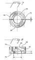
- the safety lock hose connector 49 comprises a male member 54 attached to anaesthetic apparatus 10 (as indicated at 100) and is provided with a split ring locking collar 62 attached thereto, the collar 62 and the outer surface of the male member together define an annular recess 64 and the inside wall 66 of collar 62 is provided with a pair of helical or spiral grooves 68 extending from the free outer end 70 of the collar towards the fixed end 72 of the collar.
- Tubular female member 58 having an internally tapered portion (not shown) and connected to flexible hose 76 is adapted to mate with male member 54.
- the outer wall 78 of female member 58 is provided with lugs 86 for engagement in groove 68 in collar 62.
- the safety lock connector provides metal to metal contact between the hose and the machine, which helps prevent the build-up of static electricity, which potentially could cause a spark.
- female member 58 In its operation, with reference to FIG. 9, female member 58 is brought into contact with male member 54 and loosely engaged therewith. Further forward movement (by hand) of female member 58 causes lugs 86 thereon to engage in the open ends of grooves 68 in collar 62. By rotating grip ring 60 in a clockwise direction the lugs 86, guided by the spiral locking groove 68, draw female member 58 into further contact with male member 54 until the two members lock to form a gas-tight seal. The twisting motion imparted to the female connection member by the locking ring grooves ensures good frictional lock between the two members. Axial and radial movement of the female connector is prevented by the friction between lugs 86 and the walls of groove 68.
- operation of the connector in accordance with the invention can simply be carried out as a one-handed operation as, indeed, can unlocking and disconnection of the connector which is simply affected by twisting the connector counter-clockwise by hand until lugs 86 are free to be pulled outwardly of groove 68. This rotational motion breaks the friction between the two members and align lugs 86 with the apertures in the forward face of collar 62.
- the safety lock can be easily installed on existing anaesthetic machines by merely installing the split ring locking collar on the machine.
- the locking mechanism of the invention provides a secure hose connection which can be easily and disconnected in an emergency.
Landscapes
- Health & Medical Sciences (AREA)
- Anesthesiology (AREA)
- Emergency Medicine (AREA)
- Pulmonology (AREA)
- Engineering & Computer Science (AREA)
- Biomedical Technology (AREA)
- Heart & Thoracic Surgery (AREA)
- Hematology (AREA)
- Life Sciences & Earth Sciences (AREA)
- Animal Behavior & Ethology (AREA)
- General Health & Medical Sciences (AREA)
- Public Health (AREA)
- Veterinary Medicine (AREA)
- Filling Or Discharging Of Gas Storage Vessels (AREA)
Applications Claiming Priority (2)
| Application Number | Priority Date | Filing Date | Title |
|---|---|---|---|
| US290484 | 1981-08-06 | ||
| US07/290,484 US4932398A (en) | 1988-12-23 | 1988-12-23 | Anaesthetic vaporizer interlock system and connector for anaesthetic apparatus |
Publications (2)
| Publication Number | Publication Date |
|---|---|
| EP0376649A2 true EP0376649A2 (fr) | 1990-07-04 |
| EP0376649A3 EP0376649A3 (fr) | 1991-11-27 |
Family
ID=23116214
Family Applications (1)
| Application Number | Title | Priority Date | Filing Date |
|---|---|---|---|
| EP19890313517 Withdrawn EP0376649A3 (fr) | 1988-12-23 | 1989-12-22 | Système de blocage pour vaporisateur anesthésique et connexion pour appareil d'anesthésie |
Country Status (2)
| Country | Link |
|---|---|
| US (1) | US4932398A (fr) |
| EP (1) | EP0376649A3 (fr) |
Cited By (3)
| Publication number | Priority date | Publication date | Assignee | Title |
|---|---|---|---|---|
| EP0680770A1 (fr) * | 1994-05-06 | 1995-11-08 | Siemens-Elema AB | Système de sécurité dans un système d'anesthésie |
| EP0860176A1 (fr) * | 1997-02-20 | 1998-08-26 | Siemens-Elema AB | Carrousel pour vaporisateurs |
| EP0898979A1 (fr) * | 1997-08-21 | 1999-03-03 | Siemens-Elema AB | Dispositif de préréglage d'un vaporisateur |
Families Citing this family (16)
| Publication number | Priority date | Publication date | Assignee | Title |
|---|---|---|---|---|
| DE4331035C2 (de) * | 1993-09-13 | 1995-07-20 | Draegerwerk Ag | Sicherheitsfüllvorrichtung zum Einfüllen einer Narkoseflüssigkeit |
| IT1269700B (it) * | 1994-01-07 | 1997-04-15 | Abbott Lab | Sistema e apparecchiatura per collegare un contenitore di anestetico ad un vaporizzatore |
| US5657747A (en) * | 1996-04-22 | 1997-08-19 | N.A.D., Inc. | Interface for vaporizer interlock |
| ES2139540B1 (es) * | 1998-04-14 | 2000-09-01 | Mas Marfany Jaime | Metodo de control automatico para el aporte de anestesico a un circuito cerrado a bajos flujos. |
| US6962153B2 (en) * | 2003-10-07 | 2005-11-08 | Draeger Medical, Inc. | Interlock/exclusion systems for multiple vaporizer anesthesia machines |
| US7472700B2 (en) * | 2004-08-12 | 2009-01-06 | Drager Medical Ag & Co. Kg | Adaptor for releasably mounting a vaporizer on an anesthesia machine |
| US7784504B2 (en) | 2006-03-06 | 2010-08-31 | Baxter International Inc. | Adapters for use with an anesthetic vaporizer |
| US8522839B2 (en) * | 2006-03-06 | 2013-09-03 | Baxter International Inc. | Adapters for use with an anesthetic vaporizer |
| US7743946B2 (en) * | 2006-03-28 | 2010-06-29 | Lancer Partnership, Ltd. | Method and apparatus for switching flow circuits in a product dispenser |
| US8534328B2 (en) * | 2008-04-09 | 2013-09-17 | Baxter International Inc. | Adapters for use with an anesthetic vaporizer |
| US8267081B2 (en) | 2009-02-20 | 2012-09-18 | Baxter International Inc. | Inhaled anesthetic agent therapy and delivery system |
| EP2432541B1 (fr) * | 2009-05-20 | 2013-05-01 | Baxter International Inc | Contenant et produit pharmaceutique |
| CN103285482A (zh) * | 2012-02-28 | 2013-09-11 | Ge医疗系统环球技术有限公司 | 一种蒸发罐互锁装置及麻醉机 |
| CN103908723A (zh) * | 2013-01-09 | 2014-07-09 | 深圳迈瑞生物医疗电子股份有限公司 | 多蒸发器互锁机构 |
| EP3682929B1 (fr) * | 2017-10-20 | 2022-12-07 | Shenzhen Mindray Bio-Medical Electronics Co., Ltd | Structure de verrouillage d'évaporateur d'anesthésique et machine d'anesthésie |
| CN110559535B (zh) * | 2019-10-10 | 2023-06-16 | 常州赛乐医疗技术有限公司 | 防止蒸发器误打开支座、应用该支座的蒸发器及工作方法 |
Family Cites Families (52)
| Publication number | Priority date | Publication date | Assignee | Title |
|---|---|---|---|---|
| US551733A (en) * | 1895-12-17 | Pipe-coupling | ||
| US263415A (en) * | 1882-08-29 | Coupling | ||
| US328427A (en) * | 1885-10-13 | nusbeck | ||
| US337867A (en) * | 1886-03-16 | Pipe-joint | ||
| US64292A (en) * | 1867-04-30 | douglas | ||
| US149728A (en) * | 1874-04-14 | Improvement in hose-couplings | ||
| US1307273A (en) * | 1919-06-17 | Hose-couplihg | ||
| US1256666A (en) * | 1918-02-19 | Douglas & Rudd Mfg Co | Method of forming cylindrical shells and assembling them with cores. | |
| CA378334A (fr) * | 1938-12-13 | John Buchholz Edward | Accouplement | |
| CA77160A (fr) * | 1902-05-23 | 1902-08-26 | Daniel Morrison | Joint de boyaux |
| CA77262A (fr) * | 1902-06-19 | 1902-09-02 | Gustav A. Anderson | Joint de boyaux |
| CA79816A (fr) * | 1903-02-10 | 1903-03-24 | Ernest Mayer | Joint de buyau a incendie |
| US796306A (en) * | 1905-02-17 | 1905-08-01 | Isreal W Exley | Hose-coupling. |
| CA97223A (fr) * | 1905-12-18 | 1906-01-30 | Frank W. Rehfeld | Joint de boyaux |
| US1026269A (en) * | 1911-11-20 | 1912-05-14 | George C Knauff | Attachment-plug. |
| US1117762A (en) * | 1913-02-25 | 1914-11-17 | Albert M Barcus | Coupling for hose and the like. |
| CA189092A (fr) * | 1918-09-23 | 1919-03-11 | Jean Baptiste Gagne | Raccord de boyaux |
| US1549858A (en) * | 1924-11-13 | 1925-08-18 | William T Evans | Dispensing apparatus |
| US1744367A (en) * | 1926-06-18 | 1930-01-21 | R M Hollingshead Company | Quick-detachable coupling |
| US1871370A (en) * | 1927-06-07 | 1932-08-09 | Adams Ind Inc | Coupling terminal for conduits |
| US1762572A (en) * | 1928-08-28 | 1930-06-10 | American Safety Device Co | Coupling device |
| GB1385670A (en) * | 1970-11-01 | 1975-02-26 | Cyprane Ltd | Anaesthesia machines |
| US3813115A (en) * | 1972-10-27 | 1974-05-28 | Johns Manville | Plastic pipe thrust resistant joint |
| US3876234A (en) * | 1973-01-11 | 1975-04-08 | Extracorporeal Med Spec | Twist-lock connector |
| FR2241039B1 (fr) * | 1973-08-17 | 1976-05-07 | Air Liquide | |
| US3877731A (en) * | 1973-09-14 | 1975-04-15 | Robert A Kraus | Coupling |
| LU72635A1 (fr) * | 1975-06-03 | 1977-03-03 | ||
| US4246115A (en) * | 1978-08-28 | 1981-01-20 | Cummins Engine Company, Inc. | Multi-valve interlock apparatus |
| CA1105959A (fr) * | 1979-01-15 | 1981-07-28 | Dimitrios G. Oreopoulos | Connecteur |
| GB2052271B (en) * | 1979-04-03 | 1983-03-09 | Medishield Corp Ltd | Gas administration apparatus |
| CA1222786A (fr) * | 1979-06-04 | 1987-06-09 | Baxter Travenol Laboratories, Inc. | Raccord a emmanchement conique |
| FR2458734B1 (fr) * | 1979-06-04 | 1985-06-07 | Baxter Travenol Lab | Dispositif de raccordement a blocage pour tuyaux |
| US4296949A (en) * | 1979-08-06 | 1981-10-27 | Abbott Laboratories | Rotatable connecting device for I.V. administration set |
| US4308865A (en) * | 1979-10-19 | 1982-01-05 | Airco, Inc. | Interlock system for anesthetic vaporizers |
| US4294250A (en) * | 1979-12-07 | 1981-10-13 | Baxter Travenol Laboratories, Inc. | Luer lock connection device |
| US4307718A (en) * | 1980-02-01 | 1981-12-29 | N.A.D. Inc. | Vaporizer interlock |
| DE3007755C2 (de) * | 1980-02-29 | 1983-01-27 | Drägerwerk AG, 2400 Lübeck | Narkoseeinrichtung |
| US4346701A (en) * | 1980-03-28 | 1982-08-31 | The Medishield Corporation Limited | Gas administration apparatus |
| CA1166827A (fr) * | 1981-01-19 | 1984-05-08 | Jaising Korgaonkar | Collier de tuyau |
| SE455470B (sv) * | 1981-06-23 | 1988-07-18 | Terumo Corp | Koppling for ihopkoppling av tva slangar for medicinskt, terapeutiskt bruk |
| US4477109A (en) * | 1981-07-29 | 1984-10-16 | Gfk Partnership | Connector for hoses and the like |
| US4434790A (en) * | 1981-08-18 | 1984-03-06 | Puritan-Bennett Corporation | Vaporizer subsystem for an anesthesia machine |
| US4402420A (en) * | 1981-12-07 | 1983-09-06 | Extracorporeal Medical Specialties, Inc. | Dual function port cap |
| SE453887B (sv) * | 1982-03-09 | 1988-03-14 | Terumo Corp | Anordning for overforing av medicinsk losning samt anslutningsorgan i sadan anordning |
| CA1204129A (fr) * | 1982-05-28 | 1986-05-06 | Ted Butterfield | Raccord-eclair pour tubes de fluide |
| CA1209171A (fr) * | 1982-05-28 | 1986-08-05 | Waterous Company | Accouplement pour systeme fluidique |
| DE3222047C1 (de) * | 1982-06-11 | 1983-10-20 | Drägerwerk AG, 2400 Lübeck | Sperrvorrichtung fuer Verdampfer an Narkosegeraeten |
| ZA838246B (en) * | 1982-12-01 | 1984-06-27 | Boc Group Plc | Gas mixing apparatus |
| CA1205836A (fr) * | 1982-12-15 | 1986-06-10 | Larry Hohol | Raccord pour tuyaux |
| CA1185856A (fr) * | 1983-06-08 | 1985-04-23 | Southmedic Incorporated | Dispositif de surete pour vaporisateur d'anesthesique |
| US4463754A (en) * | 1983-08-11 | 1984-08-07 | Southmedic Incorporated | Safety control and lock for anesthetic vaporizers |
| GB2193642B (en) * | 1986-08-08 | 1990-10-31 | Boc Group Plc | Gas administration apparatus |
-
1988
- 1988-12-23 US US07/290,484 patent/US4932398A/en not_active Expired - Fee Related
-
1989
- 1989-12-22 EP EP19890313517 patent/EP0376649A3/fr not_active Withdrawn
Cited By (6)
| Publication number | Priority date | Publication date | Assignee | Title |
|---|---|---|---|---|
| EP0680770A1 (fr) * | 1994-05-06 | 1995-11-08 | Siemens-Elema AB | Système de sécurité dans un système d'anesthésie |
| US5537992A (en) * | 1994-05-06 | 1996-07-23 | Siemens Elema Ab | Anesthetic system having electronic safety interlock system |
| EP0860176A1 (fr) * | 1997-02-20 | 1998-08-26 | Siemens-Elema AB | Carrousel pour vaporisateurs |
| US5921235A (en) * | 1997-02-20 | 1999-07-13 | Siemens Elema Ab | Vaporizer carousel |
| EP0898979A1 (fr) * | 1997-08-21 | 1999-03-03 | Siemens-Elema AB | Dispositif de préréglage d'un vaporisateur |
| US6302104B1 (en) | 1997-08-21 | 2001-10-16 | Siemens Elema Ab | Interlock arrangement for evaporators in an anesthesia apparatus |
Also Published As
| Publication number | Publication date |
|---|---|
| US4932398A (en) | 1990-06-12 |
| EP0376649A3 (fr) | 1991-11-27 |
Similar Documents
| Publication | Publication Date | Title |
|---|---|---|
| EP0376649A2 (fr) | Système de blocage pour vaporisateur anesthésique et connexion pour appareil d'anesthésie | |
| US4883049A (en) | Apparatus for use in refilling an anesthetic vaporizer | |
| US4693853A (en) | Anesthetic vaporizer | |
| US5687777A (en) | Anesthetic agent filler valve | |
| US20020088461A1 (en) | Anesthetic gas vaporizer with a connection arrangement for a collar-equipped gas bottle | |
| US5810001A (en) | Anesthetic transfer system | |
| US5549101A (en) | Dosage inhalator with indicating/interrupting means | |
| EP0568564B1 (fr) | Recipient pour agent anesthesique liquide | |
| US5915427A (en) | Anesthetic vaporizer draining system | |
| JP2025129341A (ja) | 薬剤充填システム | |
| US20100163030A1 (en) | Adapters for use with an anesthetic vaporizer | |
| US4346701A (en) | Gas administration apparatus | |
| US4307718A (en) | Vaporizer interlock | |
| US6745800B1 (en) | Arrangement for preventing overfill of anesthetic liquid | |
| US6962153B2 (en) | Interlock/exclusion systems for multiple vaporizer anesthesia machines | |
| US4253453A (en) | Selector valve for anesthesia machine | |
| US7886780B2 (en) | Method and apparatus for preventing drug reservoir overfill | |
| EP0578513B1 (fr) | Mécanisme de connexion | |
| US6289891B1 (en) | Safety system and method for preventing mixing of different anaesthetics in an anaesthesia system | |
| JPS6260107B2 (fr) | ||
| US7472700B2 (en) | Adaptor for releasably mounting a vaporizer on an anesthesia machine | |
| EP0455433A1 (fr) | Système d'alimentation en fluide | |
| EP0860176B1 (fr) | Carrousel pour vaporisateurs | |
| US5520168A (en) | Gas flow units | |
| US6302104B1 (en) | Interlock arrangement for evaporators in an anesthesia apparatus |
Legal Events
| Date | Code | Title | Description |
|---|---|---|---|
| PUAI | Public reference made under article 153(3) epc to a published international application that has entered the european phase |
Free format text: ORIGINAL CODE: 0009012 |
|
| AK | Designated contracting states |
Kind code of ref document: A2 Designated state(s): DE FR GB |
|
| PUAL | Search report despatched |
Free format text: ORIGINAL CODE: 0009013 |
|
| AK | Designated contracting states |
Kind code of ref document: A3 Designated state(s): DE FR GB |
|
| 17P | Request for examination filed |
Effective date: 19920507 |
|
| 17Q | First examination report despatched |
Effective date: 19931125 |
|
| STAA | Information on the status of an ep patent application or granted ep patent |
Free format text: STATUS: THE APPLICATION IS DEEMED TO BE WITHDRAWN |
|
| 18D | Application deemed to be withdrawn |
Effective date: 19940406 |