EP0376727A2 - Elektromagnetische Kanone mit vermindeter Mündungsbogenbildung und Verfahren dafür - Google Patents
Elektromagnetische Kanone mit vermindeter Mündungsbogenbildung und Verfahren dafür Download PDFInfo
- Publication number
- EP0376727A2 EP0376727A2 EP89313654A EP89313654A EP0376727A2 EP 0376727 A2 EP0376727 A2 EP 0376727A2 EP 89313654 A EP89313654 A EP 89313654A EP 89313654 A EP89313654 A EP 89313654A EP 0376727 A2 EP0376727 A2 EP 0376727A2
- Authority
- EP
- European Patent Office
- Prior art keywords
- projectile
- armature
- launcher
- current
- muzzle
- Prior art date
- Legal status (The legal status is an assumption and is not a legal conclusion. Google has not performed a legal analysis and makes no representation as to the accuracy of the status listed.)
- Withdrawn
Links
Images
Classifications
-
- F—MECHANICAL ENGINEERING; LIGHTING; HEATING; WEAPONS; BLASTING
- F41—WEAPONS
- F41B—WEAPONS FOR PROJECTING MISSILES WITHOUT USE OF EXPLOSIVE OR COMBUSTIBLE PROPELLANT CHARGE; WEAPONS NOT OTHERWISE PROVIDED FOR
- F41B6/00—Electromagnetic launchers ; Plasma-actuated launchers
- F41B6/006—Rail launchers
Definitions
- This invention relates to electromagnetic projectile launchers and, more specifically, to electromagnetic projectile launchers which include circuitry for reducing or eliminating the electrical arc which is formed at the muzzle across the launcher projectile rails when the projectile exits the launcher.
- Electromagnetic projectile launchers generally, include a pair of electrically conductive rails which guide a projectile.
- the projectile is launched by quickly injecting, or commutating, an electrical current through one of the rails which then passes through the armature of the projectile and returns to the current source through the other rail. Acceleration of the projectile is substantially produced by the interaction of the current through the armature of the projectile, and the magnetic field which is produced by the same current flowing in the conductive rails.
- the present invention is useful in eliminating or significantly reducing such undesirable arcing.
- the invention consists in apparatus for minimizing electrical arcing at the muzzle of an electromagnetic projectile launcher which includes a first section, a second section and a muzzle, characterized in that the apparatus comprises: current injecting means cooperating with the launcher for generating a generally unidirectional current i m in a first direction through the armature of the projectile when the projectile is in the first section and second section of the launcher; and electrical circuit means cooperating with the launcher and said current injecting means for supplying a generally unidirectional current i L in a direction opposite said first direction, through the armature of the projectile when the projectile is in the second section of the launcher, whereby the net current flowing through the armature of the projectile is substantially reduced when the projectile exits the muzzle.
- the invention also consists in a method for minimizing electrical arcing at the muzzle of an electromagnetic projectile launcher which includes a first section, a second section and a muzzle, characterized in that the method comprises the steps of: providing current injecting means cooperating with the launcher for generating a generally unidirectional current in a first direction through the armature of the projectile when the projectile is in the first section and second section of the launcher, and providing electrical circuit means cooperating with the launcher and said current injecting means for supplying a generally unidirectional current in a direction opposite said first direction, through the armature of the projectile, when the projectile is in the second section of the launcher; moving a projectile through the launcher; providing a generally unidirectional current in the first direction through the armature when it is in the first section and the second section of the launcher; and providing a generally unidirectional current in a direction opposite said first direction, through the armature of the projectile, when the projectile is in the second section of the launcher, whereby
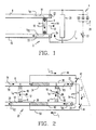
- Fig. 1 shows a projectile launcher 2 which includes muzzle arc suppressor circuitry 4 constituting a conventional counter-pulsing circuit.
- Projectile launcher 2 is designed to launch a projectile (not shown) which is mechanically attached to electrically conducting armature 6 movable along rails 8 and 10 in the direction of arrow 12 so that armature 6 exits the projectile launcher 2 at muzzle 14.
- armature 6 is accelerated in the direction of arrow 12 by injecting current in rail 8 and thereby into armature 6 in the direction of arrow 16, through armature 6 in the direction of arrow 18, and from armature 6 and into rail 10 in the direction of arrow 20.
- the current is generated by a launch power generator (not shown) which is well known to those of ordinary skill in the art.
- the interaction between the current which flows through armature 6, in the direction of arrow 18, and the magnetic field which develops as the result of current flowing through rails 8 and 10, causes armature 6 to be accelerated.
- Projectile launcher 2 has an inherent inductance, L, since a magnetic field is formed when current flows through rails 8 and 10. Rails 8 and 10 store an inductive energy equal to 1/2 Li2. Current flow i R1 and i R2 , in rails 8 and 10, can cease after armature 6 exits muzzle 14, only after the inductive energy is either depleted or transferred. The energy would primarily dissipate in the form of an electrical arc across rail ends 22 and 24 if circuitry 4 were not provided to transfer the energy.
- armature 6 exits muzzle 14 Three distinct current conduction paths will be affected at the instant that armature 6 exits muzzle 14. The first will be i R1 which is flowing in the direction of arrow 16 through rail 8 into armature 6. An arc will form between rail end 22 and armature 6 as contact between those two members is lost. The second is i m which is the current flow in the direction of arrow 18 through armature 6. The third is i R2 which is flowing in the direction of arrow 20 from armature 6 into rail 10. An arc will form between rail end 24 and armature 6 as contact is lost between those two members.
- Capacitor bank 28 is charged by an external source (not shown).
- Switch 30 is provided to discharge capacitor bank 28, thereby providing a current i c , at the moment that armature 6 exits muzzle 14.
- Current i c flows in the opposite direction of i m and is of a magnitude, generally, equal to current i m . Therefore, current i c produces a current zero value through armature 6 at the moment armature 6 exits muzzle 14.
- Capacitor bank 28 can provide a current path to accommodate the continued flow of i R1 and i R2 .
- capacitor bank 28 can not, from a practical standpoint, have a sufficient storage capacity to accommodate all of the energy without charging to a voltage level which may be enough to cause electrical arcing across rail ends 22 and 24. That is because a storage capacity of only about 100 kilojoules is necessary for generating the proper magnitude of i c while the inductive energy may be as high as 1000 kilojoules.
- Lightning arrestor 26 therefore, is provided to further facilitate the dissipation of the inductive energy.
- Lightning arrestor 26 is sized to break down and become conducting when the voltage across capacitor bank 28 and, thus, rail ends 22 and 24 is less than the voltage necessary to generate an electrical arc between the rail ends. Therefore, before an electrical arc forms across rail ends 22 and 24, lightning arrestor 26 dissipates the energy, thereby preventing the formation of electrical arcing.
- muzzle arc suppressor circuitry 4 still requires both a massive capacitor bank 28, capable of storing at least in the order of 100 kilojoules of energy, and the provision of lightning arrestor 26 at a location close enough to muzzle 14 to present a low inductance loop at rail ends 22 and 24, for effective functioning.
- a massive capacitor bank 28 capable of storing at least in the order of 100 kilojoules of energy
- lightning arrestor 26 at a location close enough to muzzle 14 to present a low inductance loop at rail ends 22 and 24, for effective functioning.
- Such arrangement of circuit elements, while technically not impossible, is impractical.
- the present invention overcomes such limitations.
- Fig. 2 shows projectile launcher 32 which employs the apparatus of the present invention.
- the apparatus of Fig. 2 is able to generate a current zero in armature 6 without capacitive storage of energy or resistances external to rails 8 and 10.
- Projectile launcher 32 includes low resistance rails 8 and 10 which supply power to and guide armature 6 in the direction of arrow 12.
- Rails 8 and 10 In series with rails 8 and 10 are greater resistive rail portions 34 and 36, respectively, which are followed, in series, by low resistive rail portions 38 and 40.
- Rail portions 34, 36, 38 and 40 also supply power to and guide armature 6 in the direction of arrow 12.
- Projectile launcher 32 functions much in the same manner as projectile launcher 2 of Fig. 1, until armature 6 reaches position B. That is because, before armature 6 reaches position B, for example when it is located at position A, virtually all of current i R1 travels through armature 6 to rail 10, bypassing the greater resistive portions 34 and 36 and rail portions 38 and 40. Therefore, i R1 equals i m , which in turn equals i R2 .
- Armature 6 travels along the greater resistive rail portions 34 and 36 upon passing position B, and until reaching position C. Switches 42 and 44 are closed when armature 6 reaches position D. An increasing ohmic rail voltage drop is generated in resistive portions 34 and 36 as armature 6 travels from B to C. This rail voltage drop, along with the back electromagnetic voltage which is inherent in launcher 32, initiates the flow of current i L in the direction of arrow 46, after switches 42 and 44 are closed. Current i L is, thus, injected into armature 6, in the direction of arrow 46, to counteract i m and produce a current zero in armature 6 to reduce or eliminate arcing when armature 6 exits muzzle 14. Preferably, i L will be exactly equal to i m at the moment when armature 6 exits muzzle 14.
- the circuitry of Fig. 2 therefore, splits current i R1 into two halves, after switches 42 and 44 are closed, with one-half of the currents flowing through armature 6 as i m and the other half flowing through armature 6 as i L .
- the calculation of the linear distance that position D is separated from position E can be readily determined by calculations involving basic mechanics and electrical circuitry, which are well known to those of ordinary skill in the art.
- a plasma or arc armature between the rails may similarly provide the conducting current path between the rails of the projectile launcher.
- a plasma or arc armature is a volume of conducting gas formed across rails 8 and 10 when no metallic current path is provided.
- the plasma or arc armature may be employed to apply the accelerating force in the form of gas pressure against a bore-sealing and electrically insulating sabot which mounts and accelerates the projectile.
- resistive portions 34 and 36 may be eliminated without compromising the operation of the invention.
- the disadvantage of eliminating resistive portions 34 and 36 is that the net armature current, as the projectile advances from position B to position E, decreases more slowly to zero thereby requiring additional rail length for proper projectile exit velocity and elimination of arcing.
- the best mode for implementing the present invention is to include resistive portions 34 and 36 in series with rails 8 and 10.
- the apparatus and method of the present invention is useful in eliminating or substantially reducing muzzle arcing when a projectile exits an electromagnetic projectile launcher without the need for external massive components such as capacitors and lightning arrestors.
Landscapes
- Engineering & Computer Science (AREA)
- Physics & Mathematics (AREA)
- Electromagnetism (AREA)
- Plasma & Fusion (AREA)
- General Engineering & Computer Science (AREA)
- Plasma Technology (AREA)
Applications Claiming Priority (2)
| Application Number | Priority Date | Filing Date | Title |
|---|---|---|---|
| US07/290,397 US4938113A (en) | 1988-12-29 | 1988-12-29 | Electromagnetic projectile launcher with reduced muzzle arcing and associated method |
| US290397 | 1988-12-29 |
Publications (2)
| Publication Number | Publication Date |
|---|---|
| EP0376727A2 true EP0376727A2 (de) | 1990-07-04 |
| EP0376727A3 EP0376727A3 (de) | 1991-04-10 |
Family
ID=23115811
Family Applications (1)
| Application Number | Title | Priority Date | Filing Date |
|---|---|---|---|
| EP19890313654 Withdrawn EP0376727A3 (de) | 1988-12-29 | 1989-12-28 | Elektromagnetische Kanone mit vermindeter Mündungsbogenbildung und Verfahren dafür |
Country Status (3)
| Country | Link |
|---|---|
| US (1) | US4938113A (de) |
| EP (1) | EP0376727A3 (de) |
| IL (1) | IL92843A0 (de) |
Families Citing this family (7)
| Publication number | Priority date | Publication date | Assignee | Title |
|---|---|---|---|---|
| JP3103861B2 (ja) * | 1993-05-12 | 2000-10-30 | 工業技術院長 | 飛翔体加速装置のサボ分離装置 |
| US5375504A (en) * | 1993-07-06 | 1994-12-27 | The United States Of America As Represented By The Secretary Of The Air Force | Augmented hypervelocity railgun with single energy source and rail segmentation |
| RU2188377C2 (ru) * | 2000-07-31 | 2002-08-27 | Чувашский государственный университет им. И.Н.Ульянова | Устройство для ускорения проводников при испытаниях материалов и изделий на ударное воздействие |
| JP5328628B2 (ja) * | 2009-12-17 | 2013-10-30 | 株式会社日本製鋼所 | 電磁レールガン |
| KR101235597B1 (ko) * | 2012-11-28 | 2013-02-21 | 국방과학연구소 | 전자기력 가속장치 |
| WO2018109434A1 (en) * | 2016-12-16 | 2018-06-21 | Bae Systems Plc | A method of slowing down a moving projectile |
| CN113237381B (zh) * | 2021-05-16 | 2023-07-28 | 南京理工大学 | 一种电磁轨道炮消弧消音装置 |
Family Cites Families (13)
| Publication number | Priority date | Publication date | Assignee | Title |
|---|---|---|---|---|
| US123A (en) * | 1837-02-10 | fairbanks | ||
| FR496325A (fr) * | 1919-03-24 | 1919-11-04 | Andre Louis Octave Fauchon Vil | Perfectionnements aux canons électriques |
| GB828865A (en) * | 1957-04-09 | 1960-02-24 | Alfred Vang | Electric circuits for preventing or minimizing arcing at circuit-breaker or switch contacts |
| NL163662C (nl) * | 1976-07-30 | 1980-09-15 | Hazemeijer Bv | In een circuit te schakelen inrichting voor het begrenzen van elektrische stroom. |
| US4319168A (en) * | 1980-01-28 | 1982-03-09 | Westinghouse Electric Corp. | Multistage electromagnetic accelerator |
| US4343223A (en) * | 1980-05-23 | 1982-08-10 | The United States Of America As Represented By The United States Department Of Energy | Multiple stage railgun |
| US4437383A (en) * | 1981-10-08 | 1984-03-20 | Westinghouse Electric Corp. | Muzzle arc suppressor for electromagnetic projectile launcher |
| US4423662A (en) * | 1981-10-08 | 1984-01-03 | Westinghouse Electric Corp. | Muzzle arc suppressor for electromagnetic projectile launcher |
| US4836083A (en) * | 1982-08-02 | 1989-06-06 | Westinghouse Electric Corp. | Alternator for rapid repetitive pulsing of an electromagnetic launcher |
| US4572964A (en) * | 1984-09-28 | 1986-02-25 | The United States Of America As Represented By The United States Department Of Energy | Counterpulse railgun energy recovery circuit |
| US4714003A (en) * | 1985-02-19 | 1987-12-22 | Westinghouse Electric Corp. | Electromagnetic launcher with a passive inductive loop for rail energy retention or dissipation |
| USH123H (en) | 1986-02-24 | 1986-09-02 | The United States Of America As Represented By The Secretary Of The Army | Self-switching electromagnetic launcher for repetitive operation |
| US4733595A (en) * | 1987-01-14 | 1988-03-29 | The United States Of America As Represented By The Secretary Of The Air Force | Muzzle arc suppressor for electromagnetic railgun |
-
1988
- 1988-12-29 US US07/290,397 patent/US4938113A/en not_active Expired - Fee Related
-
1989
- 1989-12-21 IL IL92843A patent/IL92843A0/xx unknown
- 1989-12-28 EP EP19890313654 patent/EP0376727A3/de not_active Withdrawn
Also Published As
| Publication number | Publication date |
|---|---|
| US4938113A (en) | 1990-07-03 |
| IL92843A0 (en) | 1990-09-17 |
| EP0376727A3 (de) | 1991-04-10 |
Similar Documents
| Publication | Publication Date | Title |
|---|---|---|
| US4347463A (en) | Electromagnetic projectile launcher with self-augmenting rails | |
| US4343223A (en) | Multiple stage railgun | |
| US4485720A (en) | Parallel rail electromagnetic launcher with multiple current path armature | |
| US4423662A (en) | Muzzle arc suppressor for electromagnetic projectile launcher | |
| US4437383A (en) | Muzzle arc suppressor for electromagnetic projectile launcher | |
| US4433608A (en) | Electromagnetic projectile launcher with an augmented breech | |
| US4369691A (en) | Projectile launching system with resistive insert in the breech | |
| Lehmann | Overview of the electric launch activities at the French-German Research Institute of Saint-Louis (ISL) | |
| US4714003A (en) | Electromagnetic launcher with a passive inductive loop for rail energy retention or dissipation | |
| US4577545A (en) | Parallel rail electromagnetic launcher with multiple current path armature | |
| EP0376727A2 (de) | Elektromagnetische Kanone mit vermindeter Mündungsbogenbildung und Verfahren dafür | |
| US4329971A (en) | Electromagnetic propulsion power system | |
| US4733595A (en) | Muzzle arc suppressor for electromagnetic railgun | |
| US5076136A (en) | Electromagnetic launcher system | |
| US4621561A (en) | Switch for inductive energy store transfer circuit | |
| US4858513A (en) | Electromagnetic launcher with improved rail energy recovery or dissipation | |
| US4986160A (en) | Burst firing electromagnetic launcher utilizing variable inductance coils | |
| EP0375310A1 (de) | Elektromagnetisches Geschütz mit verbesserter Stromumschaltung | |
| US4429613A (en) | Electromagnetic projectile launcher with an automatic plasma formation device | |
| EP0331446B1 (de) | Elektromagnetische Abschlussvorrichtung zur Verminderung der Chancen einer parasitären Spannungsstörung zwischen den Schienen während eines Geschossabschusses | |
| US4355561A (en) | Projectile launching system with assured current division | |
| US4987821A (en) | Electromagnetic projectile launcher with energy recovering augmenting field and minimal external field | |
| CA1256151A (en) | Low voltage arc formation in railguns | |
| JPS60138488A (ja) | 電磁式発射機 | |
| US4694729A (en) | Electromagnetic launcher assembly |
Legal Events
| Date | Code | Title | Description |
|---|---|---|---|
| PUAI | Public reference made under article 153(3) epc to a published international application that has entered the european phase |
Free format text: ORIGINAL CODE: 0009012 |
|
| AK | Designated contracting states |
Kind code of ref document: A2 Designated state(s): AT BE CH DE ES FR GB GR IT LI LU NL SE |
|
| PUAL | Search report despatched |
Free format text: ORIGINAL CODE: 0009013 |
|
| AK | Designated contracting states |
Kind code of ref document: A3 Designated state(s): AT BE CH DE ES FR GB GR IT LI LU NL SE |
|
| 17P | Request for examination filed |
Effective date: 19911007 |
|
| 17Q | First examination report despatched |
Effective date: 19920224 |
|
| STAA | Information on the status of an ep patent application or granted ep patent |
Free format text: STATUS: THE APPLICATION IS DEEMED TO BE WITHDRAWN |
|
| 18D | Application deemed to be withdrawn |
Effective date: 19920707 |