EP0376736A2 - Imprimante avec dispositif d'alimentation en papier sélectif - Google Patents
Imprimante avec dispositif d'alimentation en papier sélectif Download PDFInfo
- Publication number
- EP0376736A2 EP0376736A2 EP89313667A EP89313667A EP0376736A2 EP 0376736 A2 EP0376736 A2 EP 0376736A2 EP 89313667 A EP89313667 A EP 89313667A EP 89313667 A EP89313667 A EP 89313667A EP 0376736 A2 EP0376736 A2 EP 0376736A2
- Authority
- EP
- European Patent Office
- Prior art keywords
- sheet
- uncut
- platen
- feed
- cut sheet
- Prior art date
- Legal status (The legal status is an assumption and is not a legal conclusion. Google has not performed a legal analysis and makes no representation as to the accuracy of the status listed.)
- Ceased
Links
- 230000007246 mechanism Effects 0.000 claims abstract description 66
- 238000003780 insertion Methods 0.000 claims description 12
- 230000037431 insertion Effects 0.000 claims description 12
- 238000001514 detection method Methods 0.000 description 21
- 238000007599 discharging Methods 0.000 description 17
- 238000010586 diagram Methods 0.000 description 3
- 238000003708 edge detection Methods 0.000 description 3
- 238000013459 approach Methods 0.000 description 2
- 230000004048 modification Effects 0.000 description 2
- 238000012986 modification Methods 0.000 description 2
- 230000001174 ascending effect Effects 0.000 description 1
- 238000005452 bending Methods 0.000 description 1
- 230000002093 peripheral effect Effects 0.000 description 1
Images


Classifications
-
- B—PERFORMING OPERATIONS; TRANSPORTING
- B41—PRINTING; LINING MACHINES; TYPEWRITERS; STAMPS
- B41J—TYPEWRITERS; SELECTIVE PRINTING MECHANISMS, i.e. MECHANISMS PRINTING OTHERWISE THAN FROM A FORME; CORRECTION OF TYPOGRAPHICAL ERRORS
- B41J13/00—Devices or arrangements of selective printing mechanisms, e.g. ink-jet printers or thermal printers, specially adapted for supporting or handling copy material in short lengths, e.g. sheets
- B41J13/02—Rollers
- B41J13/036—Rollers co-operating with a roller platen
-
- B—PERFORMING OPERATIONS; TRANSPORTING
- B41—PRINTING; LINING MACHINES; TYPEWRITERS; STAMPS
- B41J—TYPEWRITERS; SELECTIVE PRINTING MECHANISMS, i.e. MECHANISMS PRINTING OTHERWISE THAN FROM A FORME; CORRECTION OF TYPOGRAPHICAL ERRORS
- B41J11/00—Devices or arrangements of selective printing mechanisms, e.g. ink-jet printers or thermal printers, for supporting or handling copy material in sheet or web form
- B41J11/0045—Guides for printing material
- B41J11/005—Guides in the printing zone, e.g. guides for preventing contact of conveyed sheets with printhead
-
- B—PERFORMING OPERATIONS; TRANSPORTING
- B41—PRINTING; LINING MACHINES; TYPEWRITERS; STAMPS
- B41J—TYPEWRITERS; SELECTIVE PRINTING MECHANISMS, i.e. MECHANISMS PRINTING OTHERWISE THAN FROM A FORME; CORRECTION OF TYPOGRAPHICAL ERRORS
- B41J11/00—Devices or arrangements of selective printing mechanisms, e.g. ink-jet printers or thermal printers, for supporting or handling copy material in sheet or web form
- B41J11/48—Apparatus for condensed record, tally strip, or like work using two or more papers, or sets of papers, e.g. devices for switching over from handling of copy material in sheet form to handling of copy material in continuous form and vice versa or point-of-sale printers comprising means for printing on continuous copy material, e.g. journal for tills, and on single sheets, e.g. cheques or receipts
- B41J11/50—Apparatus for condensed record, tally strip, or like work using two or more papers, or sets of papers, e.g. devices for switching over from handling of copy material in sheet form to handling of copy material in continuous form and vice versa or point-of-sale printers comprising means for printing on continuous copy material, e.g. journal for tills, and on single sheets, e.g. cheques or receipts in which two or more papers or sets are separately fed in the same direction towards the printing position
Definitions
- the present invention relates to a printer, such as one for an electronic cash register (hereinafter referred to as ECR) and particularly to an improvement in a paper feeding apparatus in a printer enabling selective printing on either an uncut (continuous) sheet or a cut sheet.
- ECR electronic cash register
- ECR printers contain two parallel rolls of uncut sheets with their unwound parts placed over a platen. One of the rolls is for receipt and the other roll is for journal.
- the two rolls of the uncut sheets are fed by feed rollers, and printing is conducted by a printing head which is mounted on a carriage, so that the tip of the printing head is spaced by a gap from the platen.
- the carriage is moved in parallel with the axis of the platen so that the printing head scans laterally.
- the printed part of the uncut sheet for the receipt is severed for handing to a customer as a receipt.
- the printed part of the uncut sheet for the journal is wound on a reel as a record or a journal.
- FIG. 13 and Fig. 14 An example of paper feeding mechanism for such an ECR printer is shown in Fig. 13 and Fig. 14.
- a carriage 1 carries an ink ribbon cassette 2 and a printing head 3 and is guided by both a guide shaft 4 and a guide rail 5 to move in parallel with the axis of a first platen 7 and the axis of a second platen 10.
- the first and the second platens 7 and 10 are disposed side by side and are capable of rotation independently of each other.
- An uncut sheet 6 for a receipt is placed over the first platen 7 and is held between the first platen 7 and a pressure roller 7a.
- a cutter 8 is arranged above the first platen 7 for severing the receipt sheet 6.
- a journal sheet 9 is held between the second platen 10 and a pressure roller 10a and is guided by a guide bracket 11 and then wound by a take-up reel (not shown) at a rear portion of the printer.
- a platen gear 12 is fixed to one end of the first platen 7, and is coupled to a stepping motor 16 via an idle gear 14.
- a platen gear 13 is fixed to one end of the second platen 10, and is coupled to a stepping motor 17 via an idle gear 15.
- To feed either the receipt sheet 6 or the journal sheet 9 the corresponding one of the stepping motors 16 and 17 is actuated.
- both of the stepping motors 16 and 17 are actuated.
- the conventional ECR printers are designed to feed and print cut sheets. So it cannot feed a cut sheet. It is not suitable for printing on a cut sheet.
- a cut sheet is normally wider than the uncut sheet for receipt or journal, and two platens are placed side by side leaving a gap between them, although it may be very small.
- the two platens must be rotated independently of each other, the structures for supporting them are complicated.
- the electric power supply must have a larger capacity so that two stepping motors can be energized simultaneously.
- an object of the present invention is to enable selective feeding of and printing on either a relatively narrow uncut sheet or a relatively wide cut sheet.
- Another object of the invention is to enable selective feeding of and printing on either at least one of two relatively narrow uncut sheets or a relatively wide cut sheet.
- a printer is for selectively printing on at least one uncut sheet or a cut sheet, and comprises: a platen; a printing head confronting the platen, being spaced by a gap; a motor; an uncut sheet feeding mechanism for selectively feeding or stopping said at least one uncut sheet from a roll of the uncut sheet to said gap between said printing head and said platen; said uncut sheet feeding mechanism being driven by said motor to feed the uncut sheet; a cut sheet feeding mechanism for feeding a cut sheet to said gap between said printing head and said uncut sheet on said platen; said cut sheet feeding mechanism being driven by said motor to feed the cut sheet; and control means for controlling said uncut sheet feeding mechanism and said cut sheet feeding mechanism to cause either one of them to feed and the other not to feed.
- the printer of this embodiment is capable of printing on (a) a receipt sheet only, (b) journal sheet only, (c) both a receipt sheet and a journal sheet, or (d) cut sheets.
- Each of the receipt and journal sheets are in the form of a roll of uncut sheet disposed within the housing of the printer. The cut sheets are manually inserted from outside of the housing of the printer.
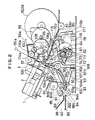
- the printer of this embodiment is an ECR printer having right and left vertical side frames 50 and 51 which are parallel with each other.
- the right and left side frames are bridged by a laterally extending supporting frame 54.
- a carriage guide shaft 52 and a carriage guide rail 53 are mounted to the supporting frame 54 to extend in parallel with each other.
- a conventional carriage 1 is slidably mounted on the carriage guide shaft 52 and the carriage guide rail 53.
- a printing head 3 is mounted on the carriage 1 such that the tip of the printing head 3 confronts the platen 57, being spaced by a gap.
- An ink ribbon cassette 2 is also mounted on the carriage 1 such that an exposed part of ink ribbon is interposed between the printing head 3 and the platen 57.
- a roll of receipt sheet 55 and a roll of journal sheet 56 are rotatably supported inside both the right side frame 50 and the left side frame 51 at the rear of (to the right of, as seen in Fig. 2) the platen 57.
- Both unwound part 55a of the receipt sheet 55 and unwound part 56a of the journal sheet 56 pass below the platen 57 and then turn upwards to pass between the platen 57 and the printing head 3. Then, the unwound part 56a of the journal sheet 56 extends backwards and wound by a take-up reel (not shown) driven a motor (also, not shown) provided at a rear portion (the right side, as seen in Fig. 2) of the printer.
- An uncut sheet guide bracket 61 is mounted at their both sides to the right side frame 50 and the left side frame 51, forming a ascending slope toward the front (the right as seen in Fig. 2).
- the guide bracket 61 guides the receipt sheet 55 and the journal sheet 56 up to a location near the printing head 3.
- a beam 115 spans between the right side frame 50 and the left side frame 51 and is located above the tape guide bracket 61, being spaced from it by a gap. Both the receipt sheet 55 and the journal sheet 56 pass through this gap.
- a pair of uncut sheet detection levers 116 (only one of which is shown in Fig.
- each paper end detection lever 116 passes through an opening of the tape guide bracket 61 to contact the beam 115 for detecting presence of the receipt sheet 55 or the journal sheet 56.
- a second end 116b is arranged to move into the space between a light-emitting element and a photosensitive element of a photoelectric sensor 117. When the second end 116b is in the space between the light-emitting element and the photosensitive element, it interrupts the path of light from the light-emitting element to the photosensitive element.
- the photoelectric sensor 117 mounted on a control printed-circuit board 83, and is electrically connected to other circuit components, such as a controller 150, as shown in Fig. 10.
- the platen 57 has a shaft 57a fixed to and coaxial with the platen 57, and a platen gear 58 is secured to the right end of the shaft 57a.
- a first stepping motor 59 is mounted to the right side frame 50, and a motor gear 59a which is secured to an output shaft of the first stepping motor 59 engages the platen gear 58 through an idle gear 60.
- the idle gear 60 is rotatably supported on the right side frame 50.
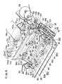
- a receipt tape feed/stop mechanism 67R and a journal tape feed/stop mechanism 67J are disposed below the platen 57. They are best illustrated in Fig. 3.
- the receipt tape feed/stop mechanism 67R includes a receipt tape pressure roller 62R, a pair of, i.e., right and left, generally flat pressure roller arm brackets 64, and the receipt tape pressure roller 62R is rotatably supported on first ends 64a of the pressure roller arm brackets 64.
- the pressure roller arm brackets 64 are rotatably mounted at their intermediate portions to opposite ends of a support shaft 65, which in turn is supported on the tape guide bracket 61, by means not shown.
- a cam follower shaft 71R is mounted at second ends of the pressure roller arm brackets 64.
- a pair of, i.e., right and left, generally flat clamp arm brackets 68 are rotatably mounted at their intermediate portions to opposite ends of the support shaft 65.
- the clamp arm brackets 68 are adjacent to and in contact with the respective pressure roller arm brackets 64, and are rotatable relative to the pressure roller arm brackets 64.
- a friction pad 70R or 70J is mounted to first ends 68a of the clamp arm brackets 68.
- a cam follower shaft 69R is mounted to second ends 68b of the clamp arm brackets 68.
- a tension spring 72 connects the second end 64b of the right pressure roller arm brackets 64 with the second end 68b of the right clamp arm bracket 68, so that the second end 64b of the right pressure roller arm bracket 64 and the second end 68b of the right clamp arm bracket 68 are pulled or biased toward each other.
- the journal tape feed/stop mechanism 67J is similar to the receipt tape feed/stop mechanism 67R, and the members similar to those of the receipt tape feed/stop mechanism 67R are given identical reference numerals, and their description is omitted.
- the journal tape pressure roller 62J, the friction pad 70J, the cam follower shafts 71J and 69J, and the cam 74J are similar to the receipt tape pressure roller 62R, the friction pad 70R, the cam follower shafts 71R and 69R, and the cam 74R, but are given different reference marks (with "R" being replaced by "J"), for the sake of convenience for the description of the operation which will be later given.
- the second end 64b of the right pressure roller arm bracket 64, the second end 68b of the right clamp arm bracket 68, and the tension spring 72 of each of the supporting mechanism 67R and journal feed/stop mechanism 67J define a triangular space, through which a first cam shaft 73 passes. Ends of the first cam shaft 73 are rotatably mounted to the right side frame 50 and the left side frame 51. A pair of feed/stop control cams 74R and 74J are mounted on first cam shaft 73. Also mounted on the first cam shaft 73 are a slit disk driving gear 75 and a cam shaft gear 76.
- the feed/stop control cam 74R is secured to the first cam shaft 73 in such a manner that it comes into contact with the cam follower shafts 71R and 69R at positions diametrically opposite with respect to the axis of the cam shaft 73, as schematically illustrated in Fig. 4A to Fig. 4D.
- the feed/stop control cam 74J is secured to the first cam shaft 73 in such a manner that it comes into contact with cam follower shafts 71J and 69J at positions diametrically opposite with respect to the axis of the cam shaft 73, as schematically illustrated in Fig. 4A to Fig. 4D.
- the feed/stop control cams 74R and 74J are typically eccentric cams, but for simpler understanding, they are illustrated to have an elevated part and a recessed part each extending about 180 o and discontinued at steps to offer an easier understanding of the concept of the function of the cam.
- the feed/stop control cams 74R and 74J have identical contours, except that their contours are 90 o out of phase relative to each other.
- cam follower shafts 71R, 71J, 69R and 69J confronts the elevated part of the cam, they are pushed by the elevated part.
- cam follower shafts 71R, 71J, 69R or 69J confront the recessed part, they are not pushed.
- the cam shaft is driven by a stepping motor, to be described later, to assume either of four positions 90 o spaced apart from each other.
- Fig. 4A, Fig. 4B, Fig. 4C and Fig. 4D shows the states in which the cam shaft is at the first, the second, the third and the fourth positions, respectively.
- the following TABLE 1 shows whether each of the cam follower shafts 71R, 71J, 69R and 69J are pushed (ON) or not pushed (OFF) at the four positions.
- the states of the cams and the feed/stop mechanism in the four positions are illustrated in the diagrams indicated at the right side of the TABLE 1.
- the slit disk driving gear 75 engages a driven gear 78 having an equal number of teeth.
- a slit disk 77 is secured to the driven gear 78, and has a radially extending slit 77a.
- the slit disk 77 is rotated synchronously with the first cam shaft 73.
- the slit disk 77 with the slit 77a cooperates with a photoelectric sensor 82.
- the peripheral part of the slit disk 77 passes between a light-emitting element and a photosensitive element of the photoelectric sensor 82, and passage of the slit 77a is detected by the photoelectric sensor 82.
- a signal PS indicating the detection of the passage of the slit 77a is supplied to the controller 150 and is used for control of the position of the cams 74R and 74J.
- the photoelectric sensor 82 is mounted on a control printed-circuit board 83.
- the cam shaft gear 76 meshes with a gear 810, which is coaxially secured to an idle gear 81.
- the idle gear 81 is rotatably mounted to a casing of a second stepping motor 79, which is secured to the right side frame 50.
- the cut sheet feeding mechanism is for feeding cut sheets that have been manually inserted into an opening 40 by the operator from the front side (left side as seen in Fig. 1 and Fig. 2).
- the cut sheet feeding mechanism includes an upwardly curved lower guide 98 and an upwardly curved upper guide 99 which is located above the lower guide 98.
- the lower guide 98 and upper guide 99 are secured to the right side frame 50 and the left side frame 51 and spaced from each other by a predetermined distance to form a cut sheet traveling passage 200.
- An upper end portion 98a of the lower guide 98 is continuous with a sloping tape guide bracket 61 which acts as a guide for the receipt sheet 55 and the journal sheet 56.
- the lower guide 98 and the tape guide bracket 61 may be formed by bending a continuous sheet.
- the upper guide 99 is provided at its upper edge with a resilient paper pressure plate 100 for resiliently directing the cut sheet or the uncut sheet toward the platen 57 so as to guide the cut sheet or the uncut sheet to travel along the platen 57.
- a first main feed roller shaft 840 transversely passes below the lower guide 98 and has three main feed rollers 84 coaxially fixed the shaft 840.
- the first main feed roller shaft 840 is rotatably mounted at its opposite ends to the right side frame 50 and the left side frame 51.
- the main feed rollers 84 partly pass through corresponding openings 98b of the lower guide 98 and project upward from the lower guide 98.
- a second main feed roller shaft 850 extends at the back of (the right side of, as seen in Fig. 2) the lower guide 98 and has also three second main feed rollers 85 coaxially fixed on it.
- the opposite ends of the second main feed roller shaft 850 are rotatably mounted to the right side frame 50 and the left side frame 51.
- the second main feed rollers 85 slightly project forwards of the lower guide 98 through corresponding openings 98c formed through the lower guide 98.
- a toothed timing belt pulley 86 is secured to a right end of the first main feed roller shaft 840.
- a toothed timing belt pulley 87 is secured to a right end of the second main feed roller shaft 850.
- a timing belt 88 strung between the toothed timing belt pulley 86 and the toothed timing belt pulley 87.
- the second main feed roller shaft 850 is provided at its right end with a driven gear 852, which engages the platen gear 58 through a gear train including an idle gear 107, an idle gear 108 and an idle gear 109.
- a pair of bell cranks 91 are rotatably mounted at opposite end portions of a support shaft 92, which is secured at its opposite ends to the right side frame 50 and the left side frame 51 and extends above the upper guide 99.
- a first arm 91a of each bell crank 91 rotatably supports a corresponding end of a sub-feed roller shaft 890.
- Three sub-feed rollers 89 are coaxially fixed on the sub-feed roller shaft 890 so that they face corresponding main feed rollers 84.
- a second arm 91b of each bell crank 91 is connected to the right side frame 50 or the left side frame 51 through a biasing tension spring 93.
- Each of the biasing tension springs 93 biases the corresponding bell crank 91 to turn in the counterclockwise direction as seen in Fig. 5.
- the bell cranks 91 are actuated by a cut sheet feeder cam mechanism 94, which includes a pair of cut sheet feeder cams 95 secured to a cam shaft 950.
- the cam shaft 950 is provided at its one end with a gear 96 which is connected to a third stepping motor 80 (Fig. 10) electrically connected to the controller 150.
- the cams 95 are eccentric cams and the largest radius portion of each cam 95 is shown to be in abutment with the second arm 91b, so that sub-feed rollers 89 are spaced from respective main feed rollers 84 by a predetermined distance.
- a pair of feed roller arms 97 are rotatably supported at their first ends to the support shaft 92, and a sub-feed roller shaft 900 are rotatably mounted to the second ends of the feed roller arms 97.
- the sub-feed roller shaft 900 has three sub-feed rollers 90 coaxially fixed on it.
- the feed roller arms 97 are biased by torsion springs (not shown) in the clockwise direction as seen in Fig. 5, so that the sub-feed rollers 90 are urged in a direction to come into contact with corresponding second main feed rollers 85 through respective openings 99c formed in the upper guide 99.
- the sub-feed rollers 90 are therefore normally kept in contact with corresponding second main feed rollers 85.
- the cut sheet feeding mechanism further includes a cut sheet insertion detection lever 101 and a cut sheet position detection lever 104.
- the cut sheet insertion detection lever 101 is rotatably supported on a shaft 102 for rotation about the shaft 102.
- the shaft 102 is secured to the lower guide 98.
- a first arm 101a of the cut sheet insertion detection lever 101 passes through an opening 98d in the lower guide 98 and an opening 99d in the upper guide 99 and a second arm 101b passes between a light-emitting element and a photosensitive element (not specifically shown) of a photoelectric sensor 103 mounted on the control printed-circuit board 83.
- the cut sheet position detection lever 104 is rotatably supported on a shaft 105, for rotation about the shaft 105.
- the shaft 105 is secured to the lower guide 98.
- a first arm 104a of the cut sheet position detection lever 104 passes through an opening 98e in the lower guide 98 and an opening 99e in the upper guide 99. It is so arranged that in normal condition, the tip of the first arm 104a of the cut sheet position detection lever 104 is near and at a predetermined distance from the printing head 3.
- a second arm 104b passes through a light-emitting element and a photosensitive element (not specifically shown) of a photoelectric sensor 106, which is also mounted on the control printed-circuit board 83.
- the cut sheet position detection lever 104 When the front edge of the cut sheet hits the upper end of the first arm 104a of the cut sheet position detection lever 104, the cut sheet position detection lever 104 is turned clockwise as seen in Fig. 2, so that the second arm of the position detection lever 104 moves out of the space between the light-emitting element and the photosensitive element of the photoelectric sensor 106. In response, the photoelectric sensor 106 generates a cut sheet front edge detection signal ES, which is supplied to the controller 150, as shown in Fig. 10. Thus, approach of the front edge of the cut sheet to the printing head 3 is detected.
- ES cut sheet front edge detection signal
- the printer is further provided with a cut sheet discharging mechanism which includes three cut sheet discharging rollers 110a, and three cut sheet discharging sub-rollers 114a.
- the cut sheet discharging rollers 110a are secured on a cut sheet discharging roller shaft 110 which is rotatably supported at its opposite ends to the right side frame 50 and the left side frame 51.
- the cut sheet discharging roller shaft 110 is provided at its right hand end with a driven gear 111, which engages a platen gear 58 through an idle gear 113.
- the cut sheet discharging sub-rollers 114a are mounted on the cut sheet discharging sub-roller shaft 114 which are rotatably mounted at its opposite ends to the right side frame 50 and the left side frame 51 in such a manner that the cut sheet discharging sub-rollers 114a come into contact with the corresponding cut sheet discharging rollers 110a.
- the receipt sheet 55 and the journal sheet 56 are narrower than the spacings between adjacent cut sheet discharging rollers 110a, and are positioned between the adjacent cut sheet discharging rollers 110a. Accordingly, they do not receive any feeding force from the cut sheet discharging rollers 110a, and are therefore not fed by them.
- the second stepping motor 79 is energized to turn the feed/stop control cams 74 to the first position shown in Fig. 3 and Fig. 4A. In this position, the feed/stop control cams 74 push the cam follower shafts 71R and 71J of the clamp arm brackets 68 of the receipt feed/stop mechanism 67R and the journal feed/stop mechanism 67J.
- the friction pads 70R and 70J on the clamp arm brackets 68 are therefore separated from the beam 115, as shown in Fig. 2, and the receipt tape pressure roller 62R and the journal tape pressure roller 62J are pressed against the platen 57 to hold the receipt sheet 55 and the journal sheet 56 on the platen 57.
- the first stepping motor 59 is energized to rotate the platen 57 through the gear train to feed both the receipt sheet 55 and the journal sheet 56, and thus printing on the receipt sheet 55 and the journal sheet 56 is conducted by the printing head 4.
- the second stepping motor 79 When the second stepping motor 79 is activated to turn the feed/stop control cams 74 90 o in the clockwise direction to place the feed/stop control cams 74R and 74J in the second position 74 shown in Fig. 4B, and the feed/stop mechanism in the state shown in Fig. 2, the receipt tape pressure roller 62R is kept pressed against the platen 57, and the friction pad 70R of the receipt feed/stop mechanism 67R is kept separated from the beam 115. On the other hand, the journal tape pressure roller 62J is separated from the platen 57, and the friction pad 70J of the journal feed/stop mechanism 67J is pressed against the beam 115. As a result, the receipt sheet 55 is fed while the journal sheet is halted.
- the carriage 1 is moved so that the printing head 3 scans within the width of the receipt sheet 55 to print on the receipt sheet 55, and the printed receipt sheet 55 is moved upwards by the platen 57.
- the receipt sheet 55 is printed and fed upwards while feeding of the journal sheet 56 is stopped.
- the feed/stop control cams 74R and 74J are rotated to assume the fourth position shown in Fig. 4D, with the feed/control mechanism assuming the state shown in Fig. 7A and Fig. 7B.
- the journal pressure roller 62J is pressed against the platen 57, and the friction pad 70J of the journal feed/stop mechanism 67J is separated from the beam 115.
- the receipt tape pressure roller 62R is separated from the platen 57, and the friction pad 70R of the receipt feed/stop mechanism 67R is pressed against the beam 115.
- the journal sheet is fed while the receipt sheet is halted.
- the carriage 1 is moved so that the printing head 3 scans within the width of the journal sheet 55, and the printed journal sheet 55 is moved rearward and wound on the take-up reel.
- Printing on a cut sheet is carried out as follows: When a cut sheet is inserted through the opening 40 into the cut sheet traveling passage 200, this is detected by the combination of the cut sheet insertion detection lever 101 and the photoelectric sensor 103. Then, the second stepping motor 79 is energized to turn the feed/stop control cams 74R and 74J so that the cams 74R and 74J assume the third position shown in Fig. 4C and the feed/stop mechanisms 67R and 67J assume the states shown in Fig. 8.
- the cut sheet feeder clamp cam 95 is rotated such that sub-feed rollers 89 are lowered by the biasing springs 93 to come into contact with corresponding main feed rollers 84.
- the cut sheet 201 is held between main feed rollers 84 and sub-feed rollers 89.
- the first stepping motor 59 is activated to rotate the main feed rollers 84 and the second main feed rollers 85.
- the cut sheet 201 is fed first by both the main feed rollers 84 and the sub-feed rollers 89 and then also by the second main feed rollers 85 and the sub-feed rollers 90.
- the controller 150 activates the first stepping motor 59 to feed the cut sheet 201 a predetermined distance over both the receipt sheet 55 and journal sheet 56 on the platen 57, i.e., between the printing head 3 and the uncut sheets 55 and 56, to position the cut sheet 201 at a printing position, and then printing is conducted.
- the front edge of the cut sheet 201 is held between the cut sheet discharging rollers 110a and the cut sheet discharging sub-rollers 114a as shown in Fig. 9.
- the cut sheet discharging rollers 110a and the cut sheet discharging sub-rollers 114a are rotated by the first stepping motor 59 during feeding of the cut sheet 201, and discharge the cut sheet 201.
- the cut sheet insertion detection lever 101 and the cut sheet position detection lever 104 detect the absence of the cut sheet. The detection of the absence of the cut sheet is reflected by the signals CS and ES. In response, the controller actuates the stepping motor to return the feed/stop mechanism to the original position, i.e., the position it assumed before the insertion of the cut sheet.
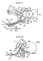
- FIG. 11 A second embodiment of the cut sheet feeding mechanism of Fig. 5 is illustrated in Fig. 11, in which like reference marks designate corresponding parts of the printer of the preceding embodiment and descriptions thereof are omitted.
- each of the main feed rollers 84 always contacts respective sub-feed rollers 310 (only one of which is shown) which are fixed on a shaft 312 rotatably mounted at its opposite ends to the right side frame 50 and the left side frame 51.
- the idle gear 107 transmits a driving force from the first stepping motor 59 to the main feed rollers 84 and second main feed rollers 85.
- An electromagnetic clutch 311 is provided to selectively connect or disconnect the idle gear 107 to and from the idle gear 108.
- the electromagnetic clutch 311 is disengaged by the controller 150 when one or both of the receipt sheet 55 and the journal sheet 56 are printed.
- the controller 150 actuates the second stepping motor 79 to place the feed/stop control cams 74R and 74J in the third position shown in Fig. 4C to stop the feeding of both the receipt sheet 55 and the journal sheet 56.
- the electromagnetic clutch 311 is engaged, while the first stepping motor 59 is kept activated. Because of the engagement of the electromagnetic clutch 311, the feed rollers are rotated and the cut sheet is therefore fed.
- the cut sheet 201 is printed by the printing head 3.
- FIG. 12 A modification of the uncut sheet feeding mechanism of Fig. 2 is shown in Fig. 12, in which like reference numerals also indicate corresponding parts of the uncut sheet feeding mechanism in Fig. 2 and descriptions thereof are omitted.
- reference numeral 300 designates a fixed flat platen secured at its opposite ends (not shown) to the right side frame 50 and the left side frame 51.
- an uncut sheet feed roller 301 is arranged to contact the receipt tape pressure roller 62R and the journal tape pressure roller 62J.
- the uncut sheet feed roller 301 is rotatably supported at its opposite ends to the right side frame 50 and the left side frame 51.
- a platen gear 58 is secured to one end of the uncut sheet feed roller 301 so that the uncut sheet feed roller 301 is rotated by the first stepping motor 59 through the gear train as in the platen 57 in Fig. 1.
- An uncut sheet guide member 302 is provided downstream of the uncut sheet feed roller 301 for guiding the receipt sheet 55 and the journal sheet 56.
- the receipt sheet 55 and journal sheet 56 are held between the uncut sheet feed roller 301 and pressure rollers 62R, 62J, and fed forwards.
- the printer prints on both the receipt sheet 55 and the journal sheet 56
- the present invention may be applied to a printer for printing on only one uncut sheet. In such a printer, only one roll of an uncut sheet is provided.
Landscapes
- Handling Of Sheets (AREA)
- Handling Of Cut Paper (AREA)
- Handling Of Continuous Sheets Of Paper (AREA)
Applications Claiming Priority (2)
| Application Number | Priority Date | Filing Date | Title |
|---|---|---|---|
| JP33148788A JPH02179770A (ja) | 1988-12-30 | 1988-12-30 | プリンタの用紙送り装置 |
| JP331487/88 | 1988-12-30 |
Publications (2)
| Publication Number | Publication Date |
|---|---|
| EP0376736A2 true EP0376736A2 (fr) | 1990-07-04 |
| EP0376736A3 EP0376736A3 (fr) | 1990-10-31 |
Family
ID=18244192
Family Applications (1)
| Application Number | Title | Priority Date | Filing Date |
|---|---|---|---|
| EP19890313667 Ceased EP0376736A3 (fr) | 1988-12-30 | 1989-12-28 | Imprimante avec dispositif d'alimentation en papier sélectif |
Country Status (2)
| Country | Link |
|---|---|
| EP (1) | EP0376736A3 (fr) |
| JP (1) | JPH02179770A (fr) |
Cited By (2)
| Publication number | Priority date | Publication date | Assignee | Title |
|---|---|---|---|---|
| DE4042486C2 (de) * | 1990-08-31 | 1994-10-06 | Data Techno Gmbh | Druckvorrichtung mit Thermodruckkopf |
| EP1120265A3 (fr) * | 2000-01-28 | 2002-07-24 | Oki Data Corporation | Appui et dispositif d'impression |
Families Citing this family (2)
| Publication number | Priority date | Publication date | Assignee | Title |
|---|---|---|---|---|
| JP2008005016A (ja) * | 2006-06-20 | 2008-01-10 | Osaki Datatech Co Ltd | 携帯型情報端末機器の印刷装置 |
| JP2018118397A (ja) * | 2017-01-23 | 2018-08-02 | 東芝テック株式会社 | プリンタ |
Family Cites Families (8)
| Publication number | Priority date | Publication date | Assignee | Title |
|---|---|---|---|---|
| IT999870B (it) * | 1973-12-03 | 1976-03-10 | Olivetti & Co Spa | Dispositivo per l alimentazione indipendente di moduli continui e discreti per macchine contabili simili |
| JPS5411417Y2 (fr) * | 1975-09-30 | 1979-05-23 | ||
| US4229113A (en) * | 1978-10-05 | 1980-10-21 | Anderson Theodore H | Shared document feed station |
| DE2946033C2 (de) * | 1979-11-14 | 1982-08-19 | Siemens AG, 1000 Berlin und 8000 München | Papiereinzugsvorrichtung für Druckeinrichtungen |
| JPS6316531Y2 (fr) * | 1981-06-19 | 1988-05-11 | ||
| JPS5852131U (ja) * | 1981-09-18 | 1983-04-08 | 中部紙土株式会社 | 包装用多層紙装 |
| JPS6019574A (ja) * | 1983-07-13 | 1985-01-31 | Tokyo Electric Co Ltd | プリンタ |
| US4786193A (en) * | 1984-05-24 | 1988-11-22 | Wang Laboratories | Pressure roller assembly |
-
1988
- 1988-12-30 JP JP33148788A patent/JPH02179770A/ja active Pending
-
1989
- 1989-12-28 EP EP19890313667 patent/EP0376736A3/fr not_active Ceased
Cited By (3)
| Publication number | Priority date | Publication date | Assignee | Title |
|---|---|---|---|---|
| DE4042486C2 (de) * | 1990-08-31 | 1994-10-06 | Data Techno Gmbh | Druckvorrichtung mit Thermodruckkopf |
| EP1120265A3 (fr) * | 2000-01-28 | 2002-07-24 | Oki Data Corporation | Appui et dispositif d'impression |
| CN1304202C (zh) * | 2000-01-28 | 2007-03-14 | 冲数据株式会社 | 压纸滚筒和打印装置 |
Also Published As
| Publication number | Publication date |
|---|---|
| EP0376736A3 (fr) | 1990-10-31 |
| JPH02179770A (ja) | 1990-07-12 |
Similar Documents
| Publication | Publication Date | Title |
|---|---|---|
| EP0180370B1 (fr) | Imprimante comprenant un dispositif d'alimentation de feuilles et de contrôle de l'éjection | |
| EP0113701B1 (fr) | Imprimante pour lieu de vente | |
| JPH08255273A (ja) | インキジェットプリンタを利用する郵便機械 | |
| US6169557B1 (en) | Recording apparatus | |
| US5139353A (en) | Printer having a single platen with multiple paper feed | |
| US4304345A (en) | Modular bidirectional tractor feed assembly | |
| US5118208A (en) | Printer with interlocked movable platen and presser | |
| US7083245B2 (en) | Recording apparatus | |
| US8341094B2 (en) | Franking machine | |
| JP2524781Y2 (ja) | プリンタにおける紙送りローラ構造 | |
| CA1139986A (fr) | Dispositif tendeur-antibouchement sur mecanisme d'amenee de feuilles | |
| EP0376736A2 (fr) | Imprimante avec dispositif d'alimentation en papier sélectif | |
| US5328280A (en) | Printer having means for switching medium feed path from sheet feed path to web feed path or vice versa | |
| JPS60210475A (ja) | プリンタのオ−トカツトシ−ト給送装置 | |
| EP1120265B1 (fr) | Appui et dispositif d'impression | |
| US4456824A (en) | Copying machine | |
| JPH10152243A (ja) | 用紙送り装置および印字装置 | |
| JPH02303872A (ja) | 自動用紙厚検知機構 | |
| JPH1110970A (ja) | サーマルプリンタ | |
| JP3952810B2 (ja) | 搬送装置及び記録装置 | |
| JP2503306Y2 (ja) | 用紙のガイド装置 | |
| JPS6378770A (ja) | 印字装置のプラテンギヤツプ自動調整機構 | |
| KR920008498B1 (ko) | 프린터에 사용되는 단표용지 공급장치 | |
| JPH066111Y2 (ja) | シ−ト供給装置 | |
| JP2578813B2 (ja) | 印字装置 |
Legal Events
| Date | Code | Title | Description |
|---|---|---|---|
| PUAI | Public reference made under article 153(3) epc to a published international application that has entered the european phase |
Free format text: ORIGINAL CODE: 0009012 |
|
| AK | Designated contracting states |
Kind code of ref document: A2 Designated state(s): DE FR GB |
|
| PUAL | Search report despatched |
Free format text: ORIGINAL CODE: 0009013 |
|
| AK | Designated contracting states |
Kind code of ref document: A3 Designated state(s): DE FR GB |
|
| 17P | Request for examination filed |
Effective date: 19901218 |
|
| 17Q | First examination report despatched |
Effective date: 19930218 |
|
| STAA | Information on the status of an ep patent application or granted ep patent |
Free format text: STATUS: THE APPLICATION HAS BEEN REFUSED |
|
| 18R | Application refused |
Effective date: 19940310 |