EP0376902B1 - Getriebesteuereinheit für Nutzfahrzeuge - Google Patents
Getriebesteuereinheit für Nutzfahrzeuge Download PDFInfo
- Publication number
- EP0376902B1 EP0376902B1 EP19890830555 EP89830555A EP0376902B1 EP 0376902 B1 EP0376902 B1 EP 0376902B1 EP 19890830555 EP19890830555 EP 19890830555 EP 89830555 A EP89830555 A EP 89830555A EP 0376902 B1 EP0376902 B1 EP 0376902B1
- Authority
- EP
- European Patent Office
- Prior art keywords
- operating unit
- tubular body
- joint
- spherical member
- connecting rod
- Prior art date
- Legal status (The legal status is an assumption and is not a legal conclusion. Google has not performed a legal analysis and makes no representation as to the accuracy of the status listed.)
- Expired - Lifetime
Links
- 238000004519 manufacturing process Methods 0.000 description 2
- 230000005540 biological transmission Effects 0.000 description 1
- 230000037431 insertion Effects 0.000 description 1
- 238000003780 insertion Methods 0.000 description 1
Images

Classifications
-
- F—MECHANICAL ENGINEERING; LIGHTING; HEATING; WEAPONS; BLASTING
- F16—ENGINEERING ELEMENTS AND UNITS; GENERAL MEASURES FOR PRODUCING AND MAINTAINING EFFECTIVE FUNCTIONING OF MACHINES OR INSTALLATIONS; THERMAL INSULATION IN GENERAL
- F16H—GEARING
- F16H61/00—Control functions within control units of change-speed- or reversing-gearings for conveying rotary motion ; Control of exclusively fluid gearing, friction gearing, gearings with endless flexible members or other particular types of gearing
- F16H61/26—Generation or transmission of movements for final actuating mechanisms
Definitions
- the present invention relates to a gearbox operating unit for commercial vehicles, of the type including a pair of operating levers connected together with the interposition of a joint and articulated with the structure of the vehicle by means of a connecting rod.
- the use of two operating levers for connecting the manual gear lever to the selector of the gearbox results both from the exigencies of bulk and the need to facilitate the tilting of the cab when it is necessary to work on the engine.
- the current solution provides for the use of a first operating lever terminating at the selector and provided, close to the universal joint connecting it to the second lever, with a ball joint connected to a connecting rod articulated with the power unit.
- the use of such a connecting rod is necessary in order to enable the transmission both of rotational movements coaxial with the levers and backward and forward movements for the selection and engagement of the various ratios of the gearbox in known manner.
- the object of the present invention is to provide an operating unit of the type specified at the beginning of the description, which does not have these disadvantages and which is simple and cheap to manufacture.
- this object is achieved by virtue of the fact that the joint includes a central spherical member with two opposite diametral appendages which are articulated with one end of the connecting rod whereas the operating levers are articulated with the connecting rod via the spherical member in correspondence with the joint.
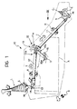
- an operating unit for operating the gearbox C of a commercial vehicle is generally indicated 10 and includes first and second operating levers, 11 and 12 respectively, interposed between the selector of the gearbox C and the manual gear lever, indicated L in the drawings, located in the driving cab of the vehicle.
- the manual gear lever L has a ball joint S housed in a spherical seat M fixed to the structure of the vehicle and a lower actuating end 13 articulated at 14 with the second operating lever 12.
- the latter has one end 12a, opposite the end articulated with the manual gear lever L, connected by a joint 15 to one end 11a of the first operating lever 11.
- the joint 15 is articulated with the structure A of the vehicle, in this instance the engine block, by means of a connecting rod 16.
- the latter has a first end 16a articulated at 17 with the structure A of the vehicle about an axis X-X which is substantially perpendicular to the longitudinal axis of the engine, and a second, forked end 16b defining a pair of arms 18.
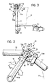
- the joint 15 includes a fork 19 fixed to the end 11a of the first operating lever 11 and provided with two seats 19a for housing pins 20a carried by an annular member 20 coaxial with a tubular body 21.
- the latter has ends 21a housed rotatably in bushes 22a fixed to the end 12a of the second operating lever 12 about an axis Y-Y substantially perpendicular to the lever itself.
- the bushes 22a which in essence constitute the "fork” 22 of the second operating lever 12 corresponding to the fork 19 of the first lever 11, are spaced from each other so as to enable the annular member 20 to be housed in the space between them, coaxially with the tubular body 21 and fixed thereto during assembly by means of a threaded dowel 23.
- the tubular body 21 and the annular member 20 fixed thereto thus constitute the "cross" of the joint 15, the arms of the cross being defined by the pins 20a connected to the annular member 20 and by the ends 21a of the tubular body 21 rotatably housed within the bushes 22a.
- the tubular body 21 has an inner wall portion 21b shaped as a spherical seat and arranged to house a spherical member 24 having diametral appendages 24a in correspondence with which a through-hole 25 is formed.
- the diametral appendages 24a of the spherical member 24 are substantially in contact with the arms 18 of the forked end 16b of the connecting rod 16.
- the inner wall of the tubular body 21 also has an annular seat 26 for housing a resilient split ring 27 for retaining the spherical member 24 in its seat 21b.
- the through-hole 25 in the spherical member 24 houses a through-pin 28 constituted, for example, by a bolt, the ends of which are inserted in suitable holes 29 formed in the arms 18 of the forked end 16b of the connecting rod 16.
- the joint 15 is assembled by means of the insertion of the tubular body 21 coaxially in the bushes 22a after the annular member 20 has been disposed coaxially with the axis Y-Y.
- the spherical member 24 is inserted in the tubular body 21 and is then prevented from leaving the spherical seat 21b by means of the resilient split ring 27 housed in its annular seat 26.
- the joint 15 is then fixed to the connecting rod 16 by means of the pin 28 which passes through the hole 25 in the spherical member 24.
- the spherical member 24 associated with its seat 21b allows the joint 15 to transmit the small rotational movements needed for the selection of the gears, indicated by the arrows R in the drawings, while fixing the joint securely to the structure of the vehicle.
- This fixing enables "axial" movements to be transmitted, these being shown by the arrows T in the drawings.
- the axial movements of the levers 11 and 12 drives the auxiliary lever M of the selector of the gearbox C, while the coaxial rotation R of the levers drives the further component C1 of the selector through an arm N.
- the operating unit 10 has a single gear-selection fulcrum located in correspondence with the point H at the centre of the spherical member 24. This improves reliability, the precision of the whole operating unit, and eliminates the component forces caused by the different positions of the fulcrum relative to the centre of rotation.
Landscapes
- Engineering & Computer Science (AREA)
- General Engineering & Computer Science (AREA)
- Mechanical Engineering (AREA)
- Gear-Shifting Mechanisms (AREA)
- Arrangement Or Mounting Of Control Devices For Change-Speed Gearing (AREA)
Claims (5)
- Getriebesteuereinheit für Nutzfahrzeuge mit einem Paar Steuerhebel (11, 12), die durch Zwischenschaltung eines Gelenks (15) zussmmengehalten und mit dem Fahrzeug selbst mittels einer Verbindungsstange (16) verbunden ist,
dadurch gekennzeichnet,
daß das Gelenk (15) ein zentrales Kugelstück (24) mit zwei entgegengesetzt angeordneten Verlängerungsstücken (24a, 28) umfaßt, wobei diese mit einem Ende (16b, 18) der Verbindungsstange (16), die Steuerhebel (11, 12) jedoch mit der Verbindungsstange (16) über das Kugelstück (24) zusammen mit dem Gelenk (15) verbunden sind. - Steuereinheit nach Anspruch 1, dadurch gekennzeichnet, daß das Gelenk (15) ein Kreuzstück mit rohrförmigem Schaft (20, 21) umfaßt, welches an seiner äußeren Seitenwand ein Paar entgegengesetzt angeordneter Stifte (20a) zur Verbindung mit einer Gabei (19) aufweist, die mit einem Ende (11a) eines ersten Hebels (11) verbunden ist, wobei die Enden (21a) des rohrförmigen Schafts (20, 21) drehbar untergebracht sind in entsprechenden zylindrischen Sitzen (22a) in Form von mit einem Ende (12a) eines zweiten Hebels (12) verbundenen Buchsen, wobei das Kugelstück (24) innerhalb des rohrförmigem Schafts (20, 21) untergebracht ist.
- Steuereinheit nach Anspruch 2, dadurch gekennzeichnet, daß der rohrförmige Schaft (21) einen zentralen, äußeren, ringförmigen Absatz (20) zwischen den zylindrischen Sitzen (22a) aufweist.
- Steuereinheit nach Anspruch 2, dadurch gekennzeichnet, daß der rohrförmige Schaft (20, 21) einen inneren Oberflächenabschnitt (21b) aufweist, der als ein dem Kugelstück (24) entsprechender sphärischer Sitz ausgebildet ist, wobei die entgegengesetzten Verlängerungsstücke (24a) des Kugelstücks (24) von den Enden (21a) des rohrförmigen Schafts (21) vorragen, um mit einem Gabelabschnitt (16b) der Verbindungsstange (16) zusammenzuwirken.
- Steuereinheit nach Anspruch 4, dadurch gekennzeichnet, daß die entgegengesetzten Verlängerungsstücke des Kugelstücks (24) gebildet sind aus den Enden eines Stifts (28), der mit einer Durchgangsbohrung (25) durch dieses Stück koaxial angeordnet ist.
Applications Claiming Priority (2)
| Application Number | Priority Date | Filing Date | Title |
|---|---|---|---|
| IT5364588U | 1988-12-27 | ||
| IT5364588U IT214962Z2 (it) | 1988-12-27 | 1988-12-27 | Gruppo di rinvio per il comando del cambio di veicoli industriali |
Publications (2)
| Publication Number | Publication Date |
|---|---|
| EP0376902A1 EP0376902A1 (de) | 1990-07-04 |
| EP0376902B1 true EP0376902B1 (de) | 1993-09-08 |
Family
ID=11284325
Family Applications (1)
| Application Number | Title | Priority Date | Filing Date |
|---|---|---|---|
| EP19890830555 Expired - Lifetime EP0376902B1 (de) | 1988-12-27 | 1989-12-19 | Getriebesteuereinheit für Nutzfahrzeuge |
Country Status (4)
| Country | Link |
|---|---|
| EP (1) | EP0376902B1 (de) |
| DE (1) | DE68909029T2 (de) |
| ES (1) | ES2044219T3 (de) |
| IT (1) | IT214962Z2 (de) |
Families Citing this family (3)
| Publication number | Priority date | Publication date | Assignee | Title |
|---|---|---|---|---|
| IT217191Z2 (it) * | 1989-09-25 | 1991-11-12 | Iveco Fiat | Gruppo di rinvio e comando del cam bio di veicoli industriali con si stema di sicurezza per evitare l autodisinnesto delle marce |
| RU2154584C1 (ru) * | 1999-01-18 | 2000-08-20 | Пак Виктор Николаевич | Механизм управления коробкой перемены передач транспортного средства (варианты) |
| SE519039C2 (sv) * | 2001-12-27 | 2002-12-23 | Scania Cv Abp | Anordning för växling av ett motorfordon |
Family Cites Families (4)
| Publication number | Priority date | Publication date | Assignee | Title |
|---|---|---|---|---|
| US2390711A (en) * | 1943-11-26 | 1945-12-11 | Kenworth Motor Truck Corp | Remote control for variable-speed transmission |
| FR93148E (fr) * | 1967-02-03 | 1969-02-14 | Simca Automobiles Sa | Dispositif de commande de boite de vitesses. |
| GB2006898B (en) * | 1977-09-14 | 1982-03-17 | Hino Motors Ltd | Transmission control device for tilt cab type automobile |
| JPS63502340A (ja) * | 1985-11-28 | 1988-09-08 | ツァ−ンラ−トファブリ−ク、フリ−ドリッヒスハ−フェン、アクチエンゲゼルシャフト | 機械式遠隔変速装置 |
-
1988
- 1988-12-27 IT IT5364588U patent/IT214962Z2/it active
-
1989
- 1989-12-19 DE DE1989609029 patent/DE68909029T2/de not_active Expired - Fee Related
- 1989-12-19 EP EP19890830555 patent/EP0376902B1/de not_active Expired - Lifetime
- 1989-12-19 ES ES89830555T patent/ES2044219T3/es not_active Expired - Lifetime
Also Published As
| Publication number | Publication date |
|---|---|
| DE68909029T2 (de) | 1994-02-03 |
| DE68909029D1 (de) | 1993-10-14 |
| EP0376902A1 (de) | 1990-07-04 |
| ES2044219T3 (es) | 1994-01-01 |
| IT214962Z2 (it) | 1990-07-30 |
| IT8853645V0 (it) | 1988-12-27 |
Similar Documents
| Publication | Publication Date | Title |
|---|---|---|
| EP0166532B1 (de) | Getriebeschalteinrichtung mit zwei Drahtzügen | |
| US5372051A (en) | Shift lever assembly for power transmission of automotive vehicle | |
| JPH0333558B2 (de) | ||
| US5765844A (en) | Linkage assembly | |
| US5063810A (en) | Shift mechanism | |
| US5819591A (en) | Shifting device for an automatic transmission of a motor vehicle | |
| EP0022632A2 (de) | Schaltvorrichtung für Getriebe | |
| CN210218647U (zh) | 操纵机构、变速箱和车辆 | |
| EP0376902A1 (de) | Getriebesteuereinheit für Nutzfahrzeuge | |
| US5029488A (en) | Bearing for the gear shift lever of the gear change box in motor vehicles | |
| US5025678A (en) | Column shift lever device | |
| FR2566342A1 (fr) | Dispositif pour la commande manuelle de la boite de vitesses d'un vehicule automobile | |
| CA1236998A (en) | Transmission for vehicle | |
| US4488448A (en) | Decoupling device for gearshift linkages | |
| JPH0419260Y2 (de) | ||
| SU1661010A1 (ru) | Устройство управлени коробкой передач | |
| JPS6232110Y2 (de) | ||
| EP0149019A2 (de) | Getriebeschalt- und Steuervorrichtung, insbesondere für Nutzfahrzeuge | |
| EP0748963A1 (de) | Schaltvorrichtung für Fahrzeuggetriebe | |
| JP3132626B2 (ja) | 自動車用変速機の操作装置 | |
| JPH0210305B2 (de) | ||
| JPS6339776Y2 (de) | ||
| EP0834684A1 (de) | Fahrzeuggetriebesteuervorrichtung und relatives Zusammensetzungsverfahren | |
| KR970010131B1 (ko) | 자동차용 수동 변속기의 변속레버장치 | |
| US3575061A (en) | Torsion rod shift mechanism for transmission |
Legal Events
| Date | Code | Title | Description |
|---|---|---|---|
| PUAI | Public reference made under article 153(3) epc to a published international application that has entered the european phase |
Free format text: ORIGINAL CODE: 0009012 |
|
| AK | Designated contracting states |
Kind code of ref document: A1 Designated state(s): DE ES FR GB IT NL SE |
|
| 17P | Request for examination filed |
Effective date: 19900919 |
|
| 17Q | First examination report despatched |
Effective date: 19920521 |
|
| GRAA | (expected) grant |
Free format text: ORIGINAL CODE: 0009210 |
|
| AK | Designated contracting states |
Kind code of ref document: B1 Designated state(s): DE ES FR GB IT NL SE |
|
| ITF | It: translation for a ep patent filed | ||
| REF | Corresponds to: |
Ref document number: 68909029 Country of ref document: DE Date of ref document: 19931014 |
|
| ET | Fr: translation filed | ||
| REG | Reference to a national code |
Ref country code: ES Ref legal event code: FG2A Ref document number: 2044219 Country of ref document: ES Kind code of ref document: T3 |
|
| PLBE | No opposition filed within time limit |
Free format text: ORIGINAL CODE: 0009261 |
|
| STAA | Information on the status of an ep patent application or granted ep patent |
Free format text: STATUS: NO OPPOSITION FILED WITHIN TIME LIMIT |
|
| 26N | No opposition filed | ||
| EAL | Se: european patent in force in sweden |
Ref document number: 89830555.2 |
|
| REG | Reference to a national code |
Ref country code: GB Ref legal event code: IF02 |
|
| NLT1 | Nl: modifications of names registered in virtue of documents presented to the patent office pursuant to art. 16 a, paragraph 1 |
Owner name: IVECO S.P.A. |
|
| REG | Reference to a national code |
Ref country code: FR Ref legal event code: CD |
|
| PGFP | Annual fee paid to national office [announced via postgrant information from national office to epo] |
Ref country code: GB Payment date: 20051205 Year of fee payment: 17 |
|
| PGFP | Annual fee paid to national office [announced via postgrant information from national office to epo] |
Ref country code: ES Payment date: 20051206 Year of fee payment: 17 |
|
| PG25 | Lapsed in a contracting state [announced via postgrant information from national office to epo] |
Ref country code: IT Free format text: LAPSE BECAUSE OF NON-PAYMENT OF DUE FEES;WARNING: LAPSES OF ITALIAN PATENTS WITH EFFECTIVE DATE BEFORE 2007 MAY HAVE OCCURRED AT ANY TIME BEFORE 2007. THE CORRECT EFFECTIVE DATE MAY BE DIFFERENT FROM THE ONE RECORDED. Effective date: 20051219 |
|
| PGFP | Annual fee paid to national office [announced via postgrant information from national office to epo] |
Ref country code: SE Payment date: 20051222 Year of fee payment: 17 Ref country code: FR Payment date: 20051222 Year of fee payment: 17 |
|
| PGFP | Annual fee paid to national office [announced via postgrant information from national office to epo] |
Ref country code: NL Payment date: 20051227 Year of fee payment: 17 |
|
| PGFP | Annual fee paid to national office [announced via postgrant information from national office to epo] |
Ref country code: DE Payment date: 20060126 Year of fee payment: 17 |
|
| REG | Reference to a national code |
Ref country code: ES Ref legal event code: PC2A |
|
| PG25 | Lapsed in a contracting state [announced via postgrant information from national office to epo] |
Ref country code: SE Free format text: LAPSE BECAUSE OF NON-PAYMENT OF DUE FEES Effective date: 20061220 |
|
| PG25 | Lapsed in a contracting state [announced via postgrant information from national office to epo] |
Ref country code: NL Free format text: LAPSE BECAUSE OF NON-PAYMENT OF DUE FEES Effective date: 20070701 |
|
| PG25 | Lapsed in a contracting state [announced via postgrant information from national office to epo] |
Ref country code: DE Free format text: LAPSE BECAUSE OF NON-PAYMENT OF DUE FEES Effective date: 20070703 |
|
| EUG | Se: european patent has lapsed | ||
| GBPC | Gb: european patent ceased through non-payment of renewal fee |
Effective date: 20061219 |
|
| NLV4 | Nl: lapsed or anulled due to non-payment of the annual fee |
Effective date: 20070701 |
|
| REG | Reference to a national code |
Ref country code: FR Ref legal event code: ST Effective date: 20070831 |
|
| PG25 | Lapsed in a contracting state [announced via postgrant information from national office to epo] |
Ref country code: GB Free format text: LAPSE BECAUSE OF NON-PAYMENT OF DUE FEES Effective date: 20061219 |
|
| REG | Reference to a national code |
Ref country code: ES Ref legal event code: FD2A Effective date: 20061220 |
|
| PG25 | Lapsed in a contracting state [announced via postgrant information from national office to epo] |
Ref country code: ES Free format text: LAPSE BECAUSE OF NON-PAYMENT OF DUE FEES Effective date: 20061220 Ref country code: FR Free format text: LAPSE BECAUSE OF NON-PAYMENT OF DUE FEES Effective date: 20070102 |
|
| PGFP | Annual fee paid to national office [announced via postgrant information from national office to epo] |
Ref country code: IT Payment date: 20081128 Year of fee payment: 20 |
|
| PGRI | Patent reinstated in contracting state [announced from national office to epo] |
Ref country code: IT Effective date: 20110616 |