EP0376925A2 - Elément d'ancrage de roche - Google Patents
Elément d'ancrage de roche Download PDFInfo
- Publication number
- EP0376925A2 EP0376925A2 EP90102315A EP90102315A EP0376925A2 EP 0376925 A2 EP0376925 A2 EP 0376925A2 EP 90102315 A EP90102315 A EP 90102315A EP 90102315 A EP90102315 A EP 90102315A EP 0376925 A2 EP0376925 A2 EP 0376925A2
- Authority
- EP
- European Patent Office
- Prior art keywords
- head
- rod
- anchor element
- washer
- particulate material
- Prior art date
- Legal status (The legal status is an assumption and is not a legal conclusion. Google has not performed a legal analysis and makes no representation as to the accuracy of the status listed.)
- Withdrawn
Links
Images


Classifications
-
- E—FIXED CONSTRUCTIONS
- E21—EARTH OR ROCK DRILLING; MINING
- E21D—SHAFTS; TUNNELS; GALLERIES; LARGE UNDERGROUND CHAMBERS
- E21D21/00—Anchoring-bolts for roof, floor in galleries or longwall working, or shaft-lining protection
- E21D21/008—Anchoring or tensioning means
-
- E—FIXED CONSTRUCTIONS
- E21—EARTH OR ROCK DRILLING; MINING
- E21D—SHAFTS; TUNNELS; GALLERIES; LARGE UNDERGROUND CHAMBERS
- E21D20/00—Setting anchoring-bolts
- E21D20/02—Setting anchoring-bolts with provisions for grouting
-
- E—FIXED CONSTRUCTIONS
- E21—EARTH OR ROCK DRILLING; MINING
- E21D—SHAFTS; TUNNELS; GALLERIES; LARGE UNDERGROUND CHAMBERS
- E21D21/00—Anchoring-bolts for roof, floor in galleries or longwall working, or shaft-lining protection
- E21D21/0026—Anchoring-bolts for roof, floor in galleries or longwall working, or shaft-lining protection characterised by constructional features of the bolts
Definitions
- the invention relates to an anchor element to be anchored in a borehole in a substrate.
- an anchor element having a head of a defined shape is advantageous when the load bearing annulus formed in situ using a supply of particulate material.
- an anchor element comprising a length of bolt or rod having a head towards or at one end to compact particulate material and disc member movable along the element characterised in that the head comprises a single plate having a radially inwardly extending tear or cut defining a gap arranged to allow particulate material to move across the plate on rotation of the element.
- the gap has an included angle of about 60°.
- the plate of the head may have more than one gap. The dimensions of the gap will be selected according to the nature of the particulate material to be passed therethrough.
- the plate may be a separate item secured to the end of the anchor element or the plate may be integrally formed.
- the disc member is flexible and takes the form of a washer which is freely movable on the anchor element.
- the anchor element may comprise a cable or length of bar with or without surface deformations.
- the element may be made of metal, e.g. steel as in concrete reinforcing bar, glass fibre, carbon fibre, or the like.
- the end of the anchor element adjacent the free end of the hole may be threaded or define a hook or otherwise be suitably shaped.
- the particulate material is a material having few natural fracture planes and an aggregate crushing value of from about 6 to about 20.
- the aggregate crushing value is preferably measured according to British Standard BS 812; Part 3; 1975.
- a material for the purpose of this invention has an aggregate crushing value of from about 6 to about 20, preferably about 10.
- Preferred materials are volcanic in origin, being dense and granular with few natural fracture planes. Specific preferred materials are andalusite, andesite (value of about 9); basalt (value of about 10); dolerite; emery (value of about 8); and flint (value of about 9).
- the hardness of the material is not relevant because many so-called hard materials have natural planes of weakness in shear and so are not suitable for use in this invention.
- the particles will typically measure about 0 to 10 mm in diameter, a mixture of sizes may be used.
- the particles tend first to slide over each other and then to interlock, so building a series of arches which together define a large arch bridging a gap, e.g. an annular gap between the borehole walls or between the anchor element and the facing wall portion. Because of their aggregate crushing value the particles can slide and interlock in this way. If the aggregate crushing value is too low, particles tend to be comminuted and the fine particles formed fill voids between the uncrushed particles but the load bearing properties are inadequate.
- the particulate material is selected from those specified above but other materials such as metal ball bearings can be used, so long as they can be compacted in the manner described without slippage to form an adequate load bearing annulus.
- the particulate material may contain additives arranged to be activated once the load bearing annulus has been formed.
- additives arranged to be activated once the load bearing annulus has been formed.
- a dry cement powder, setting accelerators, thixotropic agents and the like may be present, and the composition formed may be wetted immediately prior to use so that after the compaction, the cement will set for enhanced properties.
- the borehole may have any orientation, e.g. upward, downward, vertical or at an angle, or horizontal.
- the borehole may be formed in any substrate in which a relatively accurate hole can be formed, e.g. drilled, therein.
- the substrate may be for example a rock, sandstone, concrete, timber or the like.
- the anchor element may be point anchored quickly and efficiently to provide an immediate and high load bearing capacity, e.g. up to about 25 tonnes.
- the element is cheaper and more reliable than an all metal anchor element and can be installed with equal or faster speed to provide a better load bearing.
- the element can be installed and loaded much more quickly than in the case of a chemically setting system, e.g. a resin or cement grout.
- the metal components of the anchor element can, where necessary, be recovered and reused, e.g. in the case of single side shuttering.
- the invention further includes the anchorage formed, as a point anchor or full column anchor, whether stressed or unstressed.
- the anchor element shown in Figure 1 comprises a high tensile steel rod 10 which is threaded at one end and has a head 12, a lock nut 14, a metal washer plate 16 and a sliding rubber washer 18.
- the head comprises a forged auger which is welded or screwed to the rod 10.
- the outside diameter of the auger is slightly smaller than the diameter of the bore hole in which the anchor element is to be received.
- the sliding washer 18 comprises three rubber washers which are a friction fit on the rod 10. (The number of washers is not critical).
- the outer diameter of the washers is slightly larger than the hole diameter.
- the nut 14 is locked to the threaded end of the bolt in any convenient manner such as by upset threads on the nut or rod until a predetermined torque between the nut and rod releases the lock to enable the nut to travel on the threads.
- the washer 18 is freely movable on the rod 10.
- one or more capsules containing particulate material A are fed to the blind end of a predrilled hole.
- An anchor element according to Figure 1 is urged into the hole until the head 12 is hard up against the underside of the capsule.
- the resilient washer 18 deforms into the shape of the hole but remains located against the underside of the head 12.
- a socket wrench (not shown) which is attached to a suitable drive mechanism is now engaged with the nut 14 and the nut is spun in an anti-clockwise direction to advance the auger head 12 into the capsule.
- the particulate material A is fed by the head 12, as illustrated in Figure 2, down past the head towards the washer 18.
- the pressure of the particles on the washer forces the washer down the length of the rod as the auger head moves up the hole through the particles until the compacted particles (dark zone in Figure 2) jam the head and rod in the hole by the compaction of the particles on themselves, the side of the hole, the rod 10 and its head 12.
- the particles above the head 12 and immediately above the washer 18 are uncompressed with the washer 18 serving merely as a plug to prevent them from dribbling from the hole.
- the anchor element of Figure 3 is for use as a rock anchor and includes a threaded rod 40, a head 41, a roofing washer 42, a nut 44 which is free running on the rod threads, a small free washer 46, and swages 48 which are punched into the rod adjacent its free end.
- the head 41 is in the form of an auger and is formed by upsetting and forging the end of the rod.
- a predrilled hole is filled with capsules C.
- the nut 44 is run down the rod thread to jam the washer 46 up against the swages 48 and the rod is spun into the hole in a direction which holds the nut against the washer 46 and causes the head 41 to advance its way through the encapsulated material in the hole.
- the head 41 could be of any shape which is capable of boring through the material in the hole to compact the particles and the washer 46, although useful to prevent the nut from binding and locking onto the swages while the rod is being spun at high torque into the hole, could be omitted.
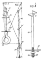
- the anchor element of Figures 4 and 5 comprises a length of steel 50 or the like having at its leading end a head 51 and a flexible disc like washer 52 spaced a short distance from the head 51.
- the head 51 comprises a generally circular metal plate secured, e.g. by welding to the end of the steel length.
- the diameter of the plate is slightly less than that of the borehole B to receive the anchor element.
- the plate has a radially inwardly extending tear or cut 53 and the opposite edge portions 54A, 54B, of the cut are bent respectively up and down out of the horizontal plane of the plate 51 so that a gap G is formed.
- the gap G is dimensioned so that particles of the aggregate A can pass therethrough.
- the included angle of the gap G in the vertical direction is about 60°.
- the flexible washer 52 comprises an annulus of rubber or fibre reinforced plastics or the like which in the relaxed condition is of frustoconical form, the inner edge 55 gripping the surface of the element 50.
- the diameter of the sleeve is substantially equal to that of the borehole B.
- particulate material in a capsule is supplied to the blind end E of the borehole, e.g. by being propelled there using a pneumatic gun.
- the steel length is then urged up the hole towards the capsule and is rotated by means not shown as it advances.
- the head 51 contacts the capsule, it starts to break the capsule wall and release the loose particulate material.
- the upper edge 54B directs the particulate material to flow through the gap G into the space between the underside of the plate and the top of the flexible disc 52. Continued rotation of the length draws more material into that gap and the particles tend to be drawn closer together to form an annulus of compacted material A bridging the borehole.
- the annulus so formed will have more resistance than the friction grip of the washer to the steel length and the washer will tend to move down the length so allowing the height of the annulus to be increased and all of the available loose particulate material to be compacted.
- the plate may have more than one gap G, the size of the gap will be adjusted according to the nature of the particulate material; the plate need not be at the free end of the steel length.
Landscapes
- Engineering & Computer Science (AREA)
- Mining & Mineral Resources (AREA)
- Structural Engineering (AREA)
- Life Sciences & Earth Sciences (AREA)
- General Life Sciences & Earth Sciences (AREA)
- Geochemistry & Mineralogy (AREA)
- Geology (AREA)
- Piles And Underground Anchors (AREA)
- Joining Of Building Structures In Genera (AREA)
Applications Claiming Priority (8)
| Application Number | Priority Date | Filing Date | Title |
|---|---|---|---|
| GB8631004 | 1986-12-30 | ||
| GB868631004A GB8631004D0 (en) | 1986-12-30 | 1986-12-30 | Anchoring |
| ZA873194 | 1987-05-05 | ||
| ZA873194 | 1987-05-05 | ||
| ZA876480 | 1987-08-31 | ||
| ZA876840 | 1987-08-31 | ||
| GB878728475A GB8728475D0 (en) | 1986-12-30 | 1987-12-10 | Anchor element |
| GB8728475 | 1987-12-10 |
Related Parent Applications (2)
| Application Number | Title | Priority Date | Filing Date |
|---|---|---|---|
| EP87311072A Division EP0278172A1 (fr) | 1986-12-30 | 1987-12-16 | Ancrage |
| EP87311072.0 Division | 1987-12-16 |
Publications (2)
| Publication Number | Publication Date |
|---|---|
| EP0376925A2 true EP0376925A2 (fr) | 1990-07-04 |
| EP0376925A3 EP0376925A3 (fr) | 1990-09-05 |
Family
ID=27449863
Family Applications (3)
| Application Number | Title | Priority Date | Filing Date |
|---|---|---|---|
| EP87311072A Withdrawn EP0278172A1 (fr) | 1986-12-30 | 1987-12-16 | Ancrage |
| EP19900102315 Withdrawn EP0376925A3 (fr) | 1986-12-30 | 1987-12-16 | Elément d'ancrage de roche |
| EP19900102314 Withdrawn EP0374130A3 (fr) | 1986-12-30 | 1987-12-16 | Ancrage de roche |
Family Applications Before (1)
| Application Number | Title | Priority Date | Filing Date |
|---|---|---|---|
| EP87311072A Withdrawn EP0278172A1 (fr) | 1986-12-30 | 1987-12-16 | Ancrage |
Family Applications After (1)
| Application Number | Title | Priority Date | Filing Date |
|---|---|---|---|
| EP19900102314 Withdrawn EP0374130A3 (fr) | 1986-12-30 | 1987-12-16 | Ancrage de roche |
Country Status (9)
| Country | Link |
|---|---|
| US (1) | US4842063A (fr) |
| EP (3) | EP0278172A1 (fr) |
| AU (2) | AU613330B2 (fr) |
| BR (1) | BR8707154A (fr) |
| GB (2) | GB8631004D0 (fr) |
| IN (1) | IN171451B (fr) |
| NO (1) | NO875336L (fr) |
| ZA (1) | ZA879562B (fr) |
| ZW (1) | ZW23787A1 (fr) |
Cited By (2)
| Publication number | Priority date | Publication date | Assignee | Title |
|---|---|---|---|---|
| FR2712938A1 (fr) * | 1993-11-26 | 1995-06-02 | Exchem Plc | Tige de fixation. |
| WO2007140159A1 (fr) * | 2006-05-30 | 2007-12-06 | Jennmar Corporation | Boulon pouvant être tendu muni d'un dispositif de suspension |
Families Citing this family (9)
| Publication number | Priority date | Publication date | Assignee | Title |
|---|---|---|---|---|
| NO167996C (no) * | 1989-09-04 | 1992-01-02 | Sinvent As | Blandeelement for fjellbolt. |
| GB2241759A (en) * | 1990-03-09 | 1991-09-11 | Fosroc International Ltd | Anchoring of bolts in boreholes |
| US5667010A (en) * | 1995-03-21 | 1997-09-16 | Steelhead Reclamation Ltd. | Process and plug for well abandonment |
| US5992522A (en) * | 1997-08-12 | 1999-11-30 | Steelhead Reclamation Ltd. | Process and seal for minimizing interzonal migration in boreholes |
| US20140010598A1 (en) * | 2010-12-24 | 2014-01-09 | Fci Holdings Delaware, Inc. | Rock Bolt |
| DE202011101508U1 (de) * | 2011-06-04 | 2012-09-05 | Gottfried Dischinger | Injektionsanker |
| US9644458B2 (en) * | 2013-10-10 | 2017-05-09 | Delta Screen & Filtration, Llc | Screen communication sleeve assembly and method |
| CA2957748C (fr) | 2017-02-13 | 2018-05-01 | Lyle Kenneth Adams | Joint de boulon a roche |
| CN112780323A (zh) * | 2021-03-09 | 2021-05-11 | 福州大学 | 地震可恢复功能锚索及其应用方法 |
Family Cites Families (11)
| Publication number | Priority date | Publication date | Assignee | Title |
|---|---|---|---|---|
| FR2223544B1 (fr) * | 1973-04-02 | 1976-05-07 | Arbed | |
| AU8743875A (en) * | 1974-12-11 | 1977-06-16 | Arnall S Eng Pty | Mine bolt |
| SU697732A1 (ru) * | 1975-09-18 | 1979-11-15 | Донецкий Научно-Исследовательский Угольный Институт | Анкерна крепь |
| ZA80816B (en) * | 1980-02-13 | 1981-01-28 | H Vidal | Method for working a mine in accordance with the bord-and-pillar method |
| JPS57155419A (en) * | 1981-03-19 | 1982-09-25 | Yuichiro Takahashi | Composition for reinforcing organic soft ground and method of ground reinforcing construction utilizing said composition |
| ZA831359B (en) * | 1982-03-04 | 1984-05-30 | Bryon Thomas Oulsnam | Roof bolts for mines and the like workings |
| SU1129373A1 (ru) * | 1982-03-09 | 1984-12-15 | Дальневосточный Ордена Трудового Красного Знамени Политехнический Институт Им.В.В.Куйбышева | Винтова анкерна крепь |
| US4501515A (en) * | 1982-06-25 | 1985-02-26 | Scott Investment Partners | Dynamic rock stabilizing fixture |
| SU1073471A1 (ru) * | 1982-10-28 | 1984-02-15 | Stepanishchev Oleg N | Анкерна крепь |
| SU1170154A1 (ru) * | 1983-02-15 | 1985-07-30 | Коммунарский горно-металлургический институт | Винтовой анкер |
| US4659258A (en) * | 1985-10-21 | 1987-04-21 | Scott Limited Partners | Dual stage dynamic rock stabilizing fixture and method of anchoring the fixture in rock formations |
-
1986
- 1986-12-30 GB GB868631004A patent/GB8631004D0/en active Pending
-
1987
- 1987-12-10 GB GB878728475A patent/GB8728475D0/en active Pending
- 1987-12-16 EP EP87311072A patent/EP0278172A1/fr not_active Withdrawn
- 1987-12-16 EP EP19900102315 patent/EP0376925A3/fr not_active Withdrawn
- 1987-12-16 EP EP19900102314 patent/EP0374130A3/fr not_active Withdrawn
- 1987-12-18 ZW ZW237/87A patent/ZW23787A1/xx unknown
- 1987-12-21 NO NO875336A patent/NO875336L/no unknown
- 1987-12-21 US US07/135,770 patent/US4842063A/en not_active Expired - Fee Related
- 1987-12-21 ZA ZA879562A patent/ZA879562B/xx unknown
- 1987-12-21 IN IN912/MAS/87A patent/IN171451B/en unknown
- 1987-12-23 AU AU82980/87A patent/AU613330B2/en not_active Ceased
- 1987-12-30 BR BR8707154A patent/BR8707154A/pt not_active IP Right Cessation
-
1991
- 1991-05-20 AU AU77156/91A patent/AU7715691A/en not_active Abandoned
Cited By (2)
| Publication number | Priority date | Publication date | Assignee | Title |
|---|---|---|---|---|
| FR2712938A1 (fr) * | 1993-11-26 | 1995-06-02 | Exchem Plc | Tige de fixation. |
| WO2007140159A1 (fr) * | 2006-05-30 | 2007-12-06 | Jennmar Corporation | Boulon pouvant être tendu muni d'un dispositif de suspension |
Also Published As
| Publication number | Publication date |
|---|---|
| BR8707154A (pt) | 1988-08-02 |
| EP0374130A3 (fr) | 1990-09-05 |
| US4842063A (en) | 1989-06-27 |
| AU613330B2 (en) | 1991-08-01 |
| EP0376925A3 (fr) | 1990-09-05 |
| IN171451B (fr) | 1992-10-17 |
| ZA879562B (en) | 1988-06-15 |
| EP0278172A1 (fr) | 1988-08-17 |
| NO875336D0 (no) | 1987-12-21 |
| ZW23787A1 (en) | 1988-05-04 |
| EP0374130A2 (fr) | 1990-06-20 |
| GB8728475D0 (en) | 1988-01-13 |
| AU8298087A (en) | 1988-06-30 |
| GB8631004D0 (en) | 1987-02-04 |
| NO875336L (no) | 1988-07-01 |
| AU7715691A (en) | 1991-08-08 |
Similar Documents
| Publication | Publication Date | Title |
|---|---|---|
| US5511909A (en) | Cable bolt and method of use in supporting a rock formation | |
| US4295761A (en) | Post tensionable grouted anchor assembly | |
| US4704053A (en) | Versatile roof bolt assembly | |
| US7927042B2 (en) | Elongate element tensioning member | |
| US5647694A (en) | Mine roof support apparatus and method | |
| US6390735B1 (en) | Apparatus and method for a yieldable tendon mine support | |
| US5314268A (en) | Non-metallic reinforcing rod and method of use in supporting a rock formation | |
| EP0376925A2 (fr) | Elément d'ancrage de roche | |
| AU2008200448B2 (en) | Tensioning assembly for a cable bolt | |
| AU2005211651B2 (en) | Point anchor coated mine roof bolt | |
| AU593055B2 (en) | Anchoring | |
| US6986623B2 (en) | Method and apparatus for anchoring a mine roof bolt | |
| US7179020B2 (en) | Mine roof bolt anchoring system and method | |
| CA2890020C (fr) | Dispositif, procede et systeme de chargement de fixatifs pour boulons d'ancrage | |
| US7296950B1 (en) | Point anchor coated mine roof bolt | |
| RU2201506C2 (ru) | Анкер | |
| JS | Friction Rock Stabilizer impact upon anchor design and ground control practices | |
| AU5933899A (en) | Rock bolt drive system | |
| AU7894798A (en) | A rock bolt assembly | |
| JPS62194344A (ja) | アンカ−要素 |
Legal Events
| Date | Code | Title | Description |
|---|---|---|---|
| PUAI | Public reference made under article 153(3) epc to a published international application that has entered the european phase |
Free format text: ORIGINAL CODE: 0009012 |
|
| AC | Divisional application: reference to earlier application |
Ref document number: 278172 Country of ref document: EP |
|
| AK | Designated contracting states |
Kind code of ref document: A2 Designated state(s): AT DE ES FR GB IT SE |
|
| PUAL | Search report despatched |
Free format text: ORIGINAL CODE: 0009013 |
|
| AK | Designated contracting states |
Kind code of ref document: A3 Designated state(s): AT DE ES FR GB IT SE |
|
| 17P | Request for examination filed |
Effective date: 19910301 |
|
| 17Q | First examination report despatched |
Effective date: 19920413 |
|
| STAA | Information on the status of an ep patent application or granted ep patent |
Free format text: STATUS: THE APPLICATION IS DEEMED TO BE WITHDRAWN |
|
| 18D | Application deemed to be withdrawn |
Effective date: 19920825 |