EP0377178B1 - Schwenkbares Liegebett - Google Patents
Schwenkbares Liegebett Download PDFInfo
- Publication number
- EP0377178B1 EP0377178B1 EP89123695A EP89123695A EP0377178B1 EP 0377178 B1 EP0377178 B1 EP 0377178B1 EP 89123695 A EP89123695 A EP 89123695A EP 89123695 A EP89123695 A EP 89123695A EP 0377178 B1 EP0377178 B1 EP 0377178B1
- Authority
- EP
- European Patent Office
- Prior art keywords
- lying
- tiltable
- bed according
- rolling
- lying bed
- Prior art date
- Legal status (The legal status is an assumption and is not a legal conclusion. Google has not performed a legal analysis and makes no representation as to the accuracy of the status listed.)
- Expired - Lifetime
Links
- 238000005096 rolling process Methods 0.000 claims abstract description 35
- 239000007788 liquid Substances 0.000 claims abstract description 20
- 230000004323 axial length Effects 0.000 claims 1
- 238000006073 displacement reaction Methods 0.000 claims 1
- 230000002441 reversible effect Effects 0.000 claims 1
- 238000000926 separation method Methods 0.000 claims 1
- 230000003187 abdominal effect Effects 0.000 description 1
- 238000010276 construction Methods 0.000 description 1
- 230000001419 dependent effect Effects 0.000 description 1
- 210000003127 knee Anatomy 0.000 description 1
- 210000002414 leg Anatomy 0.000 description 1
- 210000003205 muscle Anatomy 0.000 description 1
- 230000002040 relaxant effect Effects 0.000 description 1
- 238000005728 strengthening Methods 0.000 description 1
Images

Classifications
-
- A—HUMAN NECESSITIES
- A61—MEDICAL OR VETERINARY SCIENCE; HYGIENE
- A61H—PHYSICAL THERAPY APPARATUS, e.g. DEVICES FOR LOCATING OR STIMULATING REFLEX POINTS IN THE BODY; ARTIFICIAL RESPIRATION; MASSAGE; BATHING DEVICES FOR SPECIAL THERAPEUTIC OR HYGIENIC PURPOSES OR SPECIFIC PARTS OF THE BODY
- A61H1/00—Apparatus for passive exercising; Vibrating apparatus; Chiropractic devices, e.g. body impacting devices, external devices for briefly extending or aligning unbroken bones
- A61H1/02—Stretching or bending or torsioning apparatus for exercising
- A61H1/0218—Drawing-out devices
- A61H1/0229—Drawing-out devices by reducing gravity forces normally applied to the body, e.g. by lifting or hanging the body or part of it
-
- A—HUMAN NECESSITIES
- A61—MEDICAL OR VETERINARY SCIENCE; HYGIENE
- A61H—PHYSICAL THERAPY APPARATUS, e.g. DEVICES FOR LOCATING OR STIMULATING REFLEX POINTS IN THE BODY; ARTIFICIAL RESPIRATION; MASSAGE; BATHING DEVICES FOR SPECIAL THERAPEUTIC OR HYGIENIC PURPOSES OR SPECIFIC PARTS OF THE BODY
- A61H2203/00—Additional characteristics concerning the patient
- A61H2203/04—Position of the patient
- A61H2203/0481—Hanging
- A61H2203/0493—Hanging by hanging the patient upside down or inclined downwardly
-
- A—HUMAN NECESSITIES
- A63—SPORTS; GAMES; AMUSEMENTS
- A63B—APPARATUS FOR PHYSICAL TRAINING, GYMNASTICS, SWIMMING, CLIMBING, OR FENCING; BALL GAMES; TRAINING EQUIPMENT
- A63B2225/00—Miscellaneous features of sport apparatus, devices or equipment
- A63B2225/62—Inflatable
Definitions
- the invention relates to a swiveling bed with a rolling frame, which is formed from two at least partially circularly curved, essentially flat and parallel coupled support elements and allows any inclination of the lying surface in a certain angular range, a desired inclination by shifting one the pendulum weight provided on the frame is adjustable on an arcuate path.
- a furniture-like device has already been known, the main purpose of which is to enable relaxing lying down and sitting in various freely selectable positions. But it should also be suitable as a fitness device for strengthening the shoulder, trunk, hip, abdominal and leg muscles and, moreover, it can also be used as a normal piece of furniture that is as decorative as possible.
- the device in question is proposed with two semicircular support elements and, moreover, with the configuration described above.
- a pendulum mechanism is provided for the seat and reclining seat with a chair profile. This consists of a pendulum arm with pendulum weights arranged on it and an operating arm which is in actuation connection with the pendulum weights.
- the invention is therefore based on the object of creating a generic device which is particularly suitable for the so-called " ⁇ -training".
- Such a swiveling bed allows for a push of a button (for starting up a pump drive, which will be explained below) so that you can move your weight smoothly and gently, and with it any repeatable, exact adjustability that is required for practicing the headstand or the previous and / or subsequent rest two discrete inclinations of the lying surface. All mechanical construction parts subject to friction, which are used to suspend and handle pendulum weights, can be dispensed with.
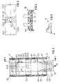
- FIGS. 1 and 2 The main parts of the subject matter of the invention can be seen from FIGS. 1 and 2. These are a bed 1, which is attached to a rolling frame 2, the latter being accommodated in a recess 3 pivotable about its center.
- the bed 1 has a frame 1.1 and a number of its longitudinal sides connecting cross struts 1.2 (see FIG. 2).
- the frame 1.1 is separated by a transverse joint 1.3 arranged approximately in the knee area of a user B, into two flat pieces, of which the smaller one can be folded or unfolded slightly in relation to the larger one and can be locked in the respective inclined position.
- On the frame 1.1 there is a mat which forms the actual lying surface 1.4, preferably made of plastic.
- the latter can expediently be designed as an eccentric.
- a headrest 1.6 is arranged to be longitudinally adjustable according to the body size of the user B.
- a neck pillow 1.7 is also provided in the head region.
- the feet of the user B are held by means of a double bracket 1.8 attached to the foot end of the lying surface 1.4.
- FIG. 4 A view of the double bracket 1.8, seen in the direction of arrow IV parallel to the lying surface 1.4, can be seen in FIG. 4:
- the foot fixation would also be conceivable by means of a set of special shoes S graded according to the foot size of the user B, for example of the same shape and color, which are each equipped with a heel hook H, with the aid of which, depending on the body size of the user B, they can each be placed in one of several in the foot area of the lying surface 1.4 on both sides of the same accessible cross struts 1.2 of the frame 1.1 can be hung (see Fig. 5).
- a displaceable weight 1.9.1 is also arranged on a beam 1.9 fastened in the head area of the lying surface 1.4 on the frame 1.1 parallel to one longitudinal side of the same, by means of which deviations of the pivoting lying bed from the horizontal equilibrium position can be compensated for by alternating users B (cf. in particular Fig. 1).
- the frame 2 mainly consists of two support elements 2.1, each in the form of a full circular tire, which are firmly connected to one another by means of axial struts 2.2, so that a roller-like, rolling frame 2 is formed.
- the circularly curved two support elements 2.1 define a rolling surface 2.3 of the rolling frame 2.
- they each have the shape of a circular cylindrical body and are fastened to the inside of the rolling surface 2.3 each with an axis of symmetry running at right angles to its circumferential direction (cf. in particular FIG. 1).
- liquid containers with a different shape, for example with Cuboid shape, can be used.
- the angle ⁇ by which the two liquid containers 2.4 lie apart on the inside of the rolling surface 2.3, determines the respectively desired two inclination positions, between which the rolling frame 2 can be pivoted together with the bed 1 arranged thereon.
- the two liquid containers 2.4 are in flow connection with one another via a pressure line 2.5 likewise laid on the inside of the rolling surface 2.3.
- a circulating pump 2.6 with an integrated electric drive is assigned to this closed pressure system.
- the angle is approximately 90 °.
- the two liquid containers 2.4 are each divided into two container halves 2.4.1, 2.4.2 for reasons of symmetry.
- a space 2.4.3 is provided between the two container halves 2.4.1, 2.4.2.
- the circulation pump 2.6 is arranged in the space 2.4.3 of the liquid container 2.4 located in FIG. 1 under the bed 1, while in the space 2.4.3 of the other liquid container 2.4 there is no closer shown balance weight is.
- a reversed arrangement of circulation pump 2.6 and balance weight would of course also be possible.
- the connections of the pressure line 2.5 are provided on the liquid containers 2.4, viewed in the direction of their axes of symmetry, in the lower region of the mutually facing jacket halves thereof and, viewed from above at right angles to the axes of symmetry, in the longitudinal center of the spaces 2.4.3. Furthermore, the container halves 2.4.1, 2.4.2 of each liquid container 2.4 each have a filling opening 2.4.4 in the upper region of their jacket half facing away from the respective other liquid container 2.4, with an associated check valve (not shown in the drawing) and a pair of counter-acting check valves 2.4 .5 for the air inlet or outlet.
- the stationary trough 3 serving as a support for the roller-like, rolling frame 2 is similar to the former with two arched rails 3.2 arranged on a trestle 3.1 and connecting them to each other.
- the rolling surface 3.4 of the trough 3 has a curvature corresponding to that of the support elements 2.1.
- a roller 3.5 is rotatably mounted in the rails in each case in the vicinity of the axial edge edges of the trough 3.
- the support elements 2.1 are supported on the rollers 3.5 and with their help the pivoting movement of the rolling frame 2 can be carried out.
- a gymnastics device 4 for example a bar or rings, can also advantageously be arranged in the rolling frame 2 above the lying surface 1.4.
- a headliner can also be provided over the lying surface 1.4 and a curtain enveloping it on all sides.
- rolling frame 2 could be designed for several beds 1.
Landscapes
- Health & Medical Sciences (AREA)
- Epidemiology (AREA)
- Pain & Pain Management (AREA)
- Physical Education & Sports Medicine (AREA)
- Rehabilitation Therapy (AREA)
- Life Sciences & Earth Sciences (AREA)
- Animal Behavior & Ethology (AREA)
- General Health & Medical Sciences (AREA)
- Public Health (AREA)
- Veterinary Medicine (AREA)
- Invalid Beds And Related Equipment (AREA)
- Vehicle Waterproofing, Decoration, And Sanitation Devices (AREA)
- Forklifts And Lifting Vehicles (AREA)
- Special Chairs (AREA)
Description
- Die Erfindung betrifft ein schwenkbares Liegebett mit einem rollenden Gestell, das aus zwei mindestens teilweise kreisförmig gebogenen, im wesentlichen ebenen und in Parallellage fest miteinander gekoppelten Auflageelementen ausgebildet ist und in einem bestimmten Winkelbereich eine beliebige Neigungslage der Liegefläche ermöglicht, wobei eine gewünschte Neigungslage durch Verlagerung eines am Gestell vorgesehenen Pendelgewichtes auf einer bogenförmigen Bahn einstellbar ist.
- Es wurde bereits eine möbelartige Vorrichtung bekannt, deren Hauptzweck die Ermöglichung eines entspannenden Liegens und Sitzens in verschiedenen, frei wählbaren Positionen ist. Sie soll sich aber auch als Fitness-Gerät zur Stärkung der Schulter-, Rumpf-, Hüft-, Bauch- und Beinmuskulatur eignen und überdies noch als ein normales, möglichst dekoratives Möbelstück verwendbar sein. Zu den genannten Zwecken wird die in Rede stehende Vorrichtung mit zwei halbkreisförmigen Auflageelementen und im übrigen mit der oben geschilderten Ausgestaltung vorgeschlagen. Zur Einstellung einer gewünschten Position der ein Stuhlprofil aufweisenden Sitz- und Liegefälche ist ein Pendelmechanismus vorgesehen. Dieser besteht aus einem Pendelarm mit daran angeordneten Pendelgewichten und einem Bedienungsarm, der mit den Pendelgewichten in Betätigungsverbindung steht.
- Im Spezialfall des sogenannt "α-training" zum Ueben von Kopfstand, u.U. begleitet von Meditation, werden lediglich diskrete Neigungslagen einer schwenkbaren Liegefläche, nämlich die waagerechte und eine angenähert senkrechte, gebraucht. Abgesehen davon, dass die Einstellung einer etwa der Körperlage beim Kopfstand entsprechenden, annäherungsweise senkrechten Neigungslage der Sitz- und Liegefläche des möbelartigen Fitness-Gerätes gemäss den obigen Schilderungen vor allem wegen der Anschläge an den beiden Enden von dessen Abrollfläche, aber auch wegen der an besagten Enden auch ohne die Anschläge zu erwartenden Instabilität mit Unfallgefahr kaum möglich ist, erscheint auch eine wünschbare Wiederholgenauigkeit bei der Einstellung irgendeiner diskreten Neigungslage mittels des Pendelmechanismus nicht als gewährleistet.
- Der Erfindung liegt daher die Aufgabe zugrunde, ein gattungsgemässes Gerät zu schaffen, das sich insbesondere für das sogenannte "α-training" eignet.
- Die Aufgabe wird mit Hilfe der Ausbildungsmerkmale gemäss dem kennzeichnenden Teil des Patentanspruches 1 gelöst.
- Ein derart beschaffenes schwenkbares Liegebett gestattet eine sozusagen durch Knopfdruck (zur Inbetriebsetzung eines weiter unten noch zu erläuternden Pumpenantriebs) stossfrei und schonungsvoll vollziehbare Gewichtsverlagerung und damit eine beliebig wiederholbare, exakte Einstellbarkeit der zu dem Ueben des Kopfstandes bzw. der vorangehenden und/oder nachfolgenden Ruhe benötigten beiden diskreten Neigungslagen der Liegefläche. Hierbei sind alle reibungsbehafteten mechanischen Konstruktionsteile verzichtbar, die zur Aufhängung und Handhabung von Pendelgewichten dienen.
- Merkmale einer besonders vorteilhaften weiteren Ausgestaltung der Erfindung bilden Gegenstand der abhängigen Patentansprüche 2 bis 17.
- Die Erfindung wird beispielsweise anhand einer bevorzugten Ausführungsform gemäss der Zeichnung näher erläutert.
- Es zeigen:
- Fig. 1: Seitenansicht eines an einem rollenden Gestell angeordneten, schwenkbaren Liegebettes gemäss der Erfindung im Schnitt längs einer in der Fig. 2 angedeuteten Schnittebene I-I;
- Fig. 2: Draufsicht auf das Liegebett nach Fig. 1 ebenfalls im Schnitt längs einer dort angegebenen Schnittebene II-II;
- Fig. 3: Obenansicht des in der unteren Endlage befindlichen Flüssigkeitsbehälters gemäss Fig. 1 in grösserem Massstab und
- Fig. 4: sowie
- Fig. 5: je eine Einzelheit, betreffend die Fixierung der Füsse des Benützers am schwenkbaren Liegebett.
- Aus den Fig. 1 und 2 sind die Hauptteile des Erfindungsgegenstandes ersichtlich. Es sind dies ein Liegebett 1, das an einem rollenden Gestell 2 befestigt ist, wobei das letztere in einer Mulde 3 um seinen Mittelpunkt verschwenkbar aufgenommen ist.
- Das Liegebett 1 weist einen Rahmen 1.1 und einer Anzahl dessen Längsseiten miteinander verbindender Querstreben 1.2 auf (vgl. Fig. 2). Der Rahmen 1.1 wird durch ein etwa im Kniebereich eines Benützers B angeordnetes Quergelenk 1.3 in zwei Flächenstücke getrennt, von denen das kleinere in bezug auf das grössere geringfügig ab- oder aufklappbar und in der jeweiligen Schräglage feststellbar ist. Auf dem Rahmen 1.1 befindet sich eine die eigentliche Liegefläche 1.4 bildende Matte vorzugsweise aus Kunststoff. Sie ist am fusseeitigen Ende des Rahmens 1.1 ortsfest verankert und mittels einer am kopfseitigen Rahmenende vorgesehenen Spannvorrichtung 1.5 spannbar. Zweckmässig kann die letztere als ein Exzenter ausgebildet sein. Auf der dem Fussbereich der Liegefläche 1.4 zugewandten Seite der Spannvorrichtung 1.5 ist eine Kopfstütze 1.6 entsprechend der Körpergrösse des Benützers B längsverstellbar angeordnet. Zur Sicherstellung der richtigen Rückenlage des Benützers B auf der Liegefläche 1.4 ist in deren Kopfbereich auch ein Nackenkissen 1.7 vorgesehen. In der veranschaulichten Ausführungsform erfolgt das Festhalten der Füsse des Benützers B anhand einer am fussseitigen Ende der Liegefläche 1.4 angebrachten Doppelbride 1.8. Diese weist vorteilhafterweise ein elastisches Futter 1.8.1 aus Kunststoff auf.
- Eine Ansicht der Doppelbride 1.8, in Richtung des Pfeils IV parallel zur Liegefläche 1.4 gesehen, lässt sich der Fig. 4 entnehmen:
- Die Fussfixierung wäre auch mittels eines Satzes nach Fussgrösse des Benützers B abgestufter Spezialschuhe S beispielsweise gleicher Form und Farbe denkbar, die je mit einem Fersenhaken H ausgestattet sind, mit dessen Hilfe sie je nach Körpergrösse des Benützers B jeweils in eine von mehreren im Fussbereich der Liegefläche 1.4 beidseits derselben zugänglichen Querstreben 1.2 des Rahmens 1.1 ein hängbar sind (vgl. Fig. 5).
- An einen im Kopfbereich der Liegefläche 1.4 am Rahmen 1.1 parallel zur einen Längsseite desselben befestigten Balken 1.9 ist ferner ein verschiebbares Gewicht 1.9.1 angeordnet, mittels dessen Abweichungen des schwenkbaren Liegebettes von der horizontalen Gleichgewichtslage wegen der Gewichtsunterschiede abwechselnder Benützer B ausgeglichen werden können (vgl. insbesondere Fig. 1).
- Wie den beiden Figuren 1 und 2 entnehmbar, besteht das Gestell 2 zur Hauptsache aus zwei je in Form eines Vollkreisreifens ausgebildeten Auflageelementen 2.1, die mittels Axialstreben 2.2 fest miteinander verbunden sind, so dass ein walzenartiges, rollendes Gestell 2 entsteht. Die kreisförmig gebogenen beiden Auflageelemente 2.1 definieren eine Abrollfläche 2.3 des rollenden Gestells 2. An der Innenseite der Abrollfläche 2.3 sind zwei in bezug aufeinander winkelverschobene und wechselseitig auffüllbare und entleerbare Flüssigkeitsbehälter 2.4 vorgesehen. Sie weisen in der vorliegenden Ausführungsform je die Gestalt eines kreiszylindrischen Körpers auf und sind an der Innenseite der Abrollfläche 2.3 jeweils mit rechtwinklig zu deren Umfangsrichtung verlaufender Symmetrieachse befestigt (vgl. insbesondere Fig. 1). Es wären jedoch Flüssigkeitsbehälter auch mit einer andersartigen Formgebung, beispielsweise mit Quaderform, einsetzbar.
- Der Winkel α, um den die beiden Flüssigkeitsbehälter 2.4 an der Innenseite der Abrollfläche 2.3 auseinanderliegen, bestimmt die jeweils gewünschten beiden Neigungslagen, zwischen denen das rollende Gestell 2 zusammen mit dem daran angeordneten Liegebett 1 verschwenkbar ist. Zur Einstellung der gewünschten Neigungslagen stehen die beiden Flüssigkeitsbehälter 2.4 über eine gleichfalls an der Innenseite der Abrollfläche 2.3 verlegte Druckleitung 2.5 miteinander in Strömungsverbindung. Diesem geschlossenen Drucksystem ist eine Umwälzpumpe 2.6 mit integriertem, elektrischen Antrieb zugeordnet.
- Bei der gezeigten Ausführungsform beträgt der Winkel angenähert 90°.
- Wie aus Figuren 2 und 3 ersichtlich, sind die beiden Flüssigkeitsbehälter 2.4 aus Symmetriegründen je in zwei Behälterhälften 2.4.1, 2.4.2 geteilt ausgeführt. Zwischen den beiden Behälterhälften 2.4.1, 2.4.2 ist jeweils ein Zwischenraum 2.4.3 vorgesehen. Bei der dargestellten Ausführung ist im Zwischenraum 2.4.3 des in der Fig. 1 unter dem Liegebett 1 befindlichen Flüssigkeitsbehälters 2.4 die Umwälzpumpe 2.6 angeordnet, während sich im Zwischenraum 2.4.3 des anderen Flüssigkeitsbehälters 2.4 ein nicht näher dargestelltes Ausgleichsgewicht befindet. Eine vertauschte Anordnung von Umwälzpumpe 2.6 und Ausgleichsgewicht wäre selbstverständlich ebenfalls möglich.
- Die Anschlüsse der Druckleitung 2.5 sind an den Flüssigkeitsbehältern 2.4, in Richtung von deren Symmetrieachsen gesehen, jeweils im unteren Bereich der einander zugewandten Mantelhälften derselben und, von oben rechtwinklig zu den Symmetrieachsen betrachtet, in der Längsmitte der Zwischenräume 2.4.3 vorgesehen. Ferner weisen die Behälterhälften 2.4.1, 2.4.2 eines jeden Flüssigkeitsbehälters 2.4 jeweils im oberen Bereich ihrer den jeweiligen anderen Flüssigkeitsbehälter 2.4 abgewandten Mantelhälfte je eine Einfüllöffnung 2.4.4 mit zugeordnetem, in der Zeichnung nicht sichtbarem Rückschlagventil sowie je ein Paar gegensinnig wirkender Rückschlagventile 2.4.5 für den Luftein- bzw. -auslass auf.
- Die als Auflager für das walzenartige, rollende Gestell 2 dienende, ortsfeste Mulde 3 ist mit zwei an einem Bock 3.1 angeordneten, bogenförmigen Schienen 3.2 und diese miteinander verbindenden Querstreben 3.3 ähnlich wie das erstere beschaffen. Die Rollfläche 3.4 der Mulde 3 weist ein derjenigen der Auflageelemente 2.1 entsprechende Krümmung auf. Jeweils in Nähe der axialen Randkanten der Mulde 3 ist in den Schienen je eine Walze 3.5 drehbar gelagert.
- Die Auflageelemente 2.1 stützen sich auf die Walzen 3.5 ab und mit deren Hilfe ist die Schwenkbewegung des rollenden Gestells 2 vollziehbar.
- Zur genauen Einstellung einer gewünschten Neigungslage der Liegefläche 1.4 besteht auch die Möglichkeit, mindestens eines der beiden Auflageelemente 2.1 mit einem nicht gezeigten Zahnkranz auszustatten, der mit einem lagegerecht an der Rollfläche 3.4 der Mulde 3 angeordneten, kraftgetriebenen, ebenfalls nicht gezeichneten Ritzel kämmt.
- Mit Vorteil lässt sich im rollenden Gestell 2 über der Liegefläche 1.4 auch ein Turngerät 4, beispielsweise Reck oder Ringe, anordnen.
- Es können zum Zwecke von Meditation alternativ auch ein Dachhimmel über der Liegefläche 1.4 und ein diese allseits umhüllender Vorhang vorgesehen sein.
- Schliesslich könnte das rollende Gestell 2 für mehrere Liegebett 1 ausgestaltet werden.
Claims (17)
Priority Applications (1)
| Application Number | Priority Date | Filing Date | Title |
|---|---|---|---|
| AT89123695T ATE75136T1 (de) | 1988-12-23 | 1989-12-21 | Schwenkbares liegebett. |
Applications Claiming Priority (2)
| Application Number | Priority Date | Filing Date | Title |
|---|---|---|---|
| CH479588 | 1988-12-23 | ||
| CH4795/88 | 1988-12-23 |
Publications (2)
| Publication Number | Publication Date |
|---|---|
| EP0377178A1 EP0377178A1 (de) | 1990-07-11 |
| EP0377178B1 true EP0377178B1 (de) | 1992-04-22 |
Family
ID=4282681
Family Applications (1)
| Application Number | Title | Priority Date | Filing Date |
|---|---|---|---|
| EP89123695A Expired - Lifetime EP0377178B1 (de) | 1988-12-23 | 1989-12-21 | Schwenkbares Liegebett |
Country Status (3)
| Country | Link |
|---|---|
| EP (1) | EP0377178B1 (de) |
| AT (1) | ATE75136T1 (de) |
| DE (1) | DE58901249D1 (de) |
Family Cites Families (3)
| Publication number | Priority date | Publication date | Assignee | Title |
|---|---|---|---|---|
| US3034152A (en) * | 1958-11-20 | 1962-05-15 | Orthopedic Frame Company | Hospital bed |
| US3286707A (en) * | 1963-10-28 | 1966-11-22 | Forest M Shafer | Rotating device with inflatable means for securing a human therein |
| US3752153A (en) * | 1972-05-05 | 1973-08-14 | D Copeland | Head stand exerciser |
-
1989
- 1989-12-21 DE DE8989123695T patent/DE58901249D1/de not_active Expired - Lifetime
- 1989-12-21 EP EP89123695A patent/EP0377178B1/de not_active Expired - Lifetime
- 1989-12-21 AT AT89123695T patent/ATE75136T1/de not_active IP Right Cessation
Also Published As
| Publication number | Publication date |
|---|---|
| ATE75136T1 (de) | 1992-05-15 |
| DE58901249D1 (de) | 1992-05-27 |
| EP0377178A1 (de) | 1990-07-11 |
Similar Documents
| Publication | Publication Date | Title |
|---|---|---|
| EP0265782A2 (de) | Sitzmöbel | |
| DE29901571U1 (de) | Trainingsgerät, insbesondere Hantelbank | |
| DE1203907B (de) | Standstuetze | |
| AT519729A1 (de) | Orthopädische Steh- und Gehhilfe | |
| DE2944599A1 (de) | Vorrichtung zur ausfuehrung gymnastischer uebungen | |
| DE2738567C3 (de) | Orthopädisches Gerät für die Wirbelsäulenstreckung bei einem sitzenden, stehenden oder gehenden Patienten | |
| DE2343020C2 (de) | Orthopädische und der Entspannung dienende Vorrichtung | |
| DE3002182C2 (de) | Stuhl, insbesondere Arbeitsstuhl bzw. Steharbeitssitz | |
| EP0377178A1 (de) | Schwenkbares Liegebett | |
| DE4003537C2 (de) | Verfahren und Vorrichtung zur Rehabilitation des Rückens | |
| DE102010012659B4 (de) | Sitzvorrichtung, insbesondere für die Therapie einer Person mit einer Behinderung | |
| DE4413752C2 (de) | Streckliege | |
| DE532709C (de) | Zahnaerztlicher Operationsstuhl | |
| DE865950C (de) | Verstellbarer Sitz- und Liegestuhl | |
| DE2709960A1 (de) | Sitzmoebel, insbesondere drehbarer arbeitsstuhl | |
| DE19819556C1 (de) | Stehgerät | |
| DE202005008754U1 (de) | Sitz und Rückentrainingvorrichtung | |
| EP0093387A1 (de) | Gesundheitsliege | |
| DE20107535U1 (de) | Hantelbank | |
| DE20001307U1 (de) | Bürofitnessstuhl | |
| DE19508886C2 (de) | Therapiebank | |
| DE19643112A1 (de) | Gymnastisches Gerät | |
| DE3330136C2 (de) | Vario-Wohnzimmersessel, umwandelbar in eine Liege und in ein Wirbelsäulenstreckgerät | |
| DE60030478T2 (de) | Streckvorrichtung | |
| DE102004034634B4 (de) | Dynamische progressive Beckenaufrichtungsvorrichtung |
Legal Events
| Date | Code | Title | Description |
|---|---|---|---|
| PUAI | Public reference made under article 153(3) epc to a published international application that has entered the european phase |
Free format text: ORIGINAL CODE: 0009012 |
|
| AK | Designated contracting states |
Kind code of ref document: A1 Designated state(s): AT BE CH DE ES FR GB GR IT LI LU NL SE |
|
| 17P | Request for examination filed |
Effective date: 19900628 |
|
| 17Q | First examination report despatched |
Effective date: 19910822 |
|
| RAP3 | Party data changed (applicant data changed or rights of an application transferred) |
Owner name: STADELMANN, HANS |
|
| ITF | It: translation for a ep patent filed | ||
| GRAA | (expected) grant |
Free format text: ORIGINAL CODE: 0009210 |
|
| AK | Designated contracting states |
Kind code of ref document: B1 Designated state(s): AT BE CH DE ES FR GB GR IT LI LU NL SE |
|
| PG25 | Lapsed in a contracting state [announced via postgrant information from national office to epo] |
Ref country code: SE Effective date: 19920422 Ref country code: NL Effective date: 19920422 Ref country code: GR Free format text: LAPSE BECAUSE OF FAILURE TO SUBMIT A TRANSLATION OF THE DESCRIPTION OR TO PAY THE FEE WITHIN THE PRESCRIBED TIME-LIMIT Effective date: 19920422 Ref country code: ES Free format text: THE PATENT HAS BEEN ANNULLED BY A DECISION OF A NATIONAL AUTHORITY Effective date: 19920422 |
|
| REF | Corresponds to: |
Ref document number: 75136 Country of ref document: AT Date of ref document: 19920515 Kind code of ref document: T |
|
| REF | Corresponds to: |
Ref document number: 58901249 Country of ref document: DE Date of ref document: 19920527 |
|
| GBT | Gb: translation of ep patent filed (gb section 77(6)(a)/1977) | ||
| REG | Reference to a national code |
Ref country code: GB Ref legal event code: 746 |
|
| ET | Fr: translation filed | ||
| NLV1 | Nl: lapsed or annulled due to failure to fulfill the requirements of art. 29p and 29m of the patents act | ||
| PG25 | Lapsed in a contracting state [announced via postgrant information from national office to epo] |
Ref country code: LU Free format text: LAPSE BECAUSE OF NON-PAYMENT OF DUE FEES Effective date: 19921231 |
|
| PLBE | No opposition filed within time limit |
Free format text: ORIGINAL CODE: 0009261 |
|
| STAA | Information on the status of an ep patent application or granted ep patent |
Free format text: STATUS: NO OPPOSITION FILED WITHIN TIME LIMIT |
|
| 26N | No opposition filed | ||
| PGFP | Annual fee paid to national office [announced via postgrant information from national office to epo] |
Ref country code: BE Payment date: 19931208 Year of fee payment: 5 |
|
| PGFP | Annual fee paid to national office [announced via postgrant information from national office to epo] |
Ref country code: GB Payment date: 19931210 Year of fee payment: 5 |
|
| PGFP | Annual fee paid to national office [announced via postgrant information from national office to epo] |
Ref country code: FR Payment date: 19941209 Year of fee payment: 6 |
|
| PGFP | Annual fee paid to national office [announced via postgrant information from national office to epo] |
Ref country code: AT Payment date: 19941215 Year of fee payment: 6 |
|
| PG25 | Lapsed in a contracting state [announced via postgrant information from national office to epo] |
Ref country code: GB Effective date: 19941221 |
|
| PG25 | Lapsed in a contracting state [announced via postgrant information from national office to epo] |
Ref country code: BE Effective date: 19941231 |
|
| BERE | Be: lapsed |
Owner name: STADELMANN HANS Effective date: 19941231 |
|
| GBPC | Gb: european patent ceased through non-payment of renewal fee |
Effective date: 19941221 |
|
| PG25 | Lapsed in a contracting state [announced via postgrant information from national office to epo] |
Ref country code: AT Effective date: 19951221 |
|
| PG25 | Lapsed in a contracting state [announced via postgrant information from national office to epo] |
Ref country code: FR Effective date: 19960830 |
|
| REG | Reference to a national code |
Ref country code: FR Ref legal event code: ST |
|
| PGFP | Annual fee paid to national office [announced via postgrant information from national office to epo] |
Ref country code: DE Payment date: 19980212 Year of fee payment: 9 |
|
| PGFP | Annual fee paid to national office [announced via postgrant information from national office to epo] |
Ref country code: CH Payment date: 19980312 Year of fee payment: 9 |
|
| PG25 | Lapsed in a contracting state [announced via postgrant information from national office to epo] |
Ref country code: LI Free format text: LAPSE BECAUSE OF NON-PAYMENT OF DUE FEES Effective date: 19981231 Ref country code: CH Free format text: LAPSE BECAUSE OF NON-PAYMENT OF DUE FEES Effective date: 19981231 |
|
| REG | Reference to a national code |
Ref country code: CH Ref legal event code: PL |
|
| PG25 | Lapsed in a contracting state [announced via postgrant information from national office to epo] |
Ref country code: DE Free format text: LAPSE BECAUSE OF NON-PAYMENT OF DUE FEES Effective date: 19991001 |
|
| PG25 | Lapsed in a contracting state [announced via postgrant information from national office to epo] |
Ref country code: IT Free format text: LAPSE BECAUSE OF NON-PAYMENT OF DUE FEES;WARNING: LAPSES OF ITALIAN PATENTS WITH EFFECTIVE DATE BEFORE 2007 MAY HAVE OCCURRED AT ANY TIME BEFORE 2007. THE CORRECT EFFECTIVE DATE MAY BE DIFFERENT FROM THE ONE RECORDED. Effective date: 20051221 |