EP0377218A2 - Surjeteuse, par exemple pour tapis - Google Patents
Surjeteuse, par exemple pour tapis Download PDFInfo
- Publication number
- EP0377218A2 EP0377218A2 EP89124060A EP89124060A EP0377218A2 EP 0377218 A2 EP0377218 A2 EP 0377218A2 EP 89124060 A EP89124060 A EP 89124060A EP 89124060 A EP89124060 A EP 89124060A EP 0377218 A2 EP0377218 A2 EP 0377218A2
- Authority
- EP
- European Patent Office
- Prior art keywords
- thread
- sewing machine
- yarn
- needle
- sewing
- Prior art date
- Legal status (The legal status is an assumption and is not a legal conclusion. Google has not performed a legal analysis and makes no representation as to the accuracy of the status listed.)
- Granted
Links
Images



Classifications
-
- D—TEXTILES; PAPER
- D05—SEWING; EMBROIDERING; TUFTING
- D05B—SEWING
- D05B1/00—General types of sewing apparatus or machines without mechanism for lateral movement of the needle or the work or both
- D05B1/08—General types of sewing apparatus or machines without mechanism for lateral movement of the needle or the work or both for making multi-thread seams
- D05B1/18—Seams for protecting or securing edges
- D05B1/20—Overedge seams
-
- D—TEXTILES; PAPER
- D05—SEWING; EMBROIDERING; TUFTING
- D05B—SEWING
- D05B37/00—Devices incorporated in sewing machines for slitting, grooving, or cutting
- D05B37/04—Cutting devices
- D05B37/06—Cutting devices with oscillating tools
-
- D—TEXTILES; PAPER
- D05—SEWING; EMBROIDERING; TUFTING
- D05D—INDEXING SCHEME ASSOCIATED WITH SUBCLASSES D05B AND D05C, RELATING TO SEWING, EMBROIDERING AND TUFTING
- D05D2203/00—Selection of machines, accessories or parts of the same kind
-
- D—TEXTILES; PAPER
- D05—SEWING; EMBROIDERING; TUFTING
- D05D—INDEXING SCHEME ASSOCIATED WITH SUBCLASSES D05B AND D05C, RELATING TO SEWING, EMBROIDERING AND TUFTING
- D05D2303/00—Applied objects or articles
- D05D2303/02—Tape
-
- D—TEXTILES; PAPER
- D10—INDEXING SCHEME ASSOCIATED WITH SUBLASSES OF SECTION D, RELATING TO TEXTILES
- D10B—INDEXING SCHEME ASSOCIATED WITH SUBLASSES OF SECTION D, RELATING TO TEXTILES
- D10B2503/00—Domestic or personal
- D10B2503/04—Floor or wall coverings; Carpets
Definitions
- the invention relates to a sewing machine, in particular for edging or hemming materials such as the edges of floor coverings or the like.
- sewing machines which are also referred to as binding machines or hemming machines
- binding machines or hemming machines are in particular to cleanly and securely bind the edges of carpets or the like, which are in the form of rolls and are cut to the size of use. It is indicated by the invention strives for the machine to be relatively easy to handle despite high performance and, if possible, also to be used in a mobile manner, because, especially when chaining very large areas, the space required to guide the entire piece of material past the machine would become too large.
- the machine according to the invention has a drive, a sewing mechanism with transport means for the material relative to the sewing mechanism, a needle mechanism and a loop formation mechanism and a thread feed to the needle and loop formation mechanism.
- the sewing mechanism which is preferably designed to form a two-thread overlock seam, has a holding gripper which retains a thread loop during the formation of an overlock loop. This preferably engages near the path of movement of the needle from below into the thread coming from a yarn gripper.
- a thread runs through the stitch holes, which only has a holding function and has no essential decorative or covering tasks.
- a very strong, high quality and thin thread can be used there, for example a thread.
- This thread is therefore called thread in the following, while thread is the thread that runs from the upper to the lower stitch row around the outer edge and, if necessary, an intermediate tuck belt and has the actual covering and decoration function.
- thread is also advantageously possible to use two yarn threads from two different bobbins together as yarn, for example to better match the color of the carpet by mixing two yarn colors in the wrapping. Accordingly, several threads are to be understood as “yarn" in the following.
- the thread is introduced by the needle, which forms loops on the top and bottom of the material with a thread threaded into a yarn gripper, an overlocking looper taking over the thread coming from the yarn gripper and in the form of a loop around the material edge the top brings.
- the thread could be the twisted loop formed on the underside in the direction of the mate Pull the edge of the rial while the overlock hook pulls yarn to form the long overlock loop.
- a holding gripper engages in the part of the yarn loop remaining on the underside of the material and holds it back as long as the usual gripper pulls the loop upwards.
- the gripper is then pulled out and the twine loop can tighten the yarn so that the lower binding formed by the yarn lies directly on the row of stitches and does not run offset to the edge. In this way, the thread tension can also be reduced because the thread no longer has to actively counteract this tendency to offset.
- the three grippers can all be arranged as oscillating grippers and can be moved mostly harmoniously and continuously, which is possible by simple crank, eccentric or lever movements. Sliding movements and other movements that are unfavorable in terms of manufacture and wear can be largely avoided. Only the holding gripper normally has a standstill phase, which can be derived from a lever movement with a simple stop.
- the grippers are designed so that their overall size is small compared to the paths they travel and their concentration in a small space allows.
- the base part receiving the looper ie the space under the material receiving table, as flat as possible, in order to have to lift the carpet only slightly when the device is mobile on partially self-steering castors, advantageously to the sewing machine to drive along the edge of the lying carpet while chaining.
- a thread guide channel through which the thread runs in opens into a position in which the thread gripper assumes a defined position, for example marked on the handwheel, for example the bottom dead center of the sewing mechanism. This aligns a threading channel, which, like the thread guide channel, ends outside the machine, so that through these two channels and the eye in between, a threading tool, e.g. in the form of a wire with a hook, passed through it and a thread can be pulled through.
- a threading tool e.g. in the form of a wire with a hook
- a sewing machine of the type mentioned at the outset can have a cutting device for the material, by means of which the corners, which usually run at right angles from the cut, can be provided with a radius suitable for weaving.
- a vertically oscillating knife is provided in front of the needle position, the cutting position of which is aligned with the edge.
- a continuous drive of this knife would not directly damage a carpet cut because it would only "scrape" along the edge, but would be unfavorable in terms of wear, volume, etc. It is therefore provided in this feature of the invention that the knife drive can be switched on and off by a knife switch-on device during the operation of the sewing mechanism.
- the knife switch-on device can preferably be actuated automatically depending on the material, for example by means of a photo cell which automatically starts the cutting device when a corner comes, ie, when the photocell placed in front of the needle position receives light from a lamp provided on the machine, while it is normally covered by the carpet during the wrapping of straight edges.
- the knife drive for example a double-sided cam, which advantageously enables two knife strokes per stitch, can run continuously, while the actual knife drive member, for example a lever interacting therewith, from a detent actuated by a magnet in the Normal position is kept out of engagement with the actuator.
- the invention provides for relieving the means of transport when cornering.
- Such relief is usually carried out manually by means of a lifting lever for the pressure foot, which presses the material against an oscillating, movable toothed rack arranged in the base part.
- a lifting lever for the pressure foot, which presses the material against an oscillating, movable toothed rack arranged in the base part.
- Such a lifting device is also provided.
- relief means are provided which automatically relieve the pressure of the pressure foot on the transport toothed strip from the spring force normally acting thereon when the cutting device is switched on.
- a particularly preferred embodiment is one in which this is done by a one-way clamping device which can be actuated by the switch-on device and which actuates the pressure foot when it is actuated is only possible to move upwards, but is stuck against a movement downwards. This prevents the pressure foot, which is normally raised and lowered a little by the lifting movement of the transport terminal strip, with each stroke, from moving back down under the spring force, so that it remains in the uppermost position of this cycle, which depends on the material thickness. In this position, with automatic adaptation to the material thickness, the covering can be rotated relative to the carpet without difficulty or injury, without losing the contact pressure required for a certain transport support and guidance.
- a guide stop can also be provided, which normally guides the edge of the material, but can be swiveled away for linking inside corners.
- a feed roller can preferably be attached to it, which runs in front of the edge of the material guide table and is so inclined that it pushes the material in the direction of the guide stop. This is particularly important if only narrow strips, for example as skirting boards, are to be linked.
- the invention also relates to a sewing machine in which the thread feeder contains at least one thread tensioner which guides the thread between two surfaces.
- One can be a roller that can be rotated with the thread, the thread being pressed on by a pressure part that is bent, for example, from sheet metal.
- Kin ken threadline knots
- Such kink formation can result, for example, from the withdrawal of the threads from an end face of a bobbin, which applies a 360 ° twist to the thread with each turn.
- the pressure part By attaching a thread eyelet to the pressure part, the pressure part can be self-regulating, ie when the thread feed tension is high, the pressure part, which is pressed in in an elastically adjustable manner, is lifted off and thus reduces the tension that is additionally applied by it. If this eyelet is attached to the inlet side of the thread tensioner, the thread tensioner reacts to resistances in the upstream thread feed, unaffected by the thread which is discontinuously withdrawn from the sewing mechanism.
- the invention also relates to a feature according to which the thread feed is designed in such a way that a thread looping around an eyelet after a thread loosening can no longer pinch itself, which has previously mostly led to thread breakage. If the eyelet is constructed in such a way that its connection to a machine part, at least in the area of the eyelet, is not narrower than the outer eyelet limit, then the thread automatically slips on it when it comes under tension, without tightening by pinching two parts of the thread lying one above the other.
- the invention provides a sewing machine for hemming or binding, which, despite great performance and the possibility of working on floor coverings of any thickness, is portable and with great reliability and high performance can also be used in rough construction site operations.
- the part receiving the thread bobbins or idler tape rolls can be folded up for transport. This can also accommodate castor wheels similar to furniture castors, while a fixed roll can be provided in the sewing area which runs in the sewing direction.
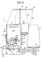
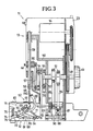
- the sewing machine 11 shown in the drawings has a lower, relatively flat base part 12 and a tower or column-like drive part 13 (FIGS. 1 and 2) projecting upwards therefrom, which comprises the drive motor 14 (FIG. 3) and the essential drive mechanisms .
- a holder 24 of a twisted bobbin 25 is provided on the removable housing 26 of the drive part.
- the housing 26 is provided with a handle 27 for transportation.
- the yarn 28 and twine 29 coming from the corresponding bobbins 21, 25 runs Via eyelets 30, which will be described later, on a thread unwinding frame 31, which can also be swiveled or removed and resilient to compensate for tension, and is then fed from above via eyelets 32 to a thread tensioner 33, which are also attached to the housing 26.
- the thread tensioners 33 each contain a base plate 34, on which a roller 36 is rotatably mounted about a horizontal axis 35 (FIG. 1).
- a pressure part 37 bent from spring steel sheet and pivotable about an axis 38 lies flat against the lateral surface 39, namely over an angle of approximately 90 ° or above.
- At the end of the pressure part opposite the axis there is a guide eyelet 40 for the thread 28 and 29 respectively.
- the pressure part 37 is pressed against the roll by means of a set screw and a spring guided therein, so that the thread is pressed flat between them. Since the roller 36 can rotate when the thread is pulled through, the pressing force of the pressing part 37 can be relatively high with a comparable tensioning or braking effect of the thread tensioner.
- thread twist before or in the thread tensioner prevents the thread from overturning (kinking) or runs through.
- An inhibition in the thread running direction in front of the thread tensioner 33 leads to a pressure reduction of the pressure part 37 by an upward pull on the eyelet 40, so that there is an automatic tension control or regulation.
- the thread 29 runs after wrapping around the roller 36 by 130 to 180 ° via a tension compensation spring 42 and an eyelet 43 to a thread lifter 44 which is oscillatingly driven together with the needle and relieves the eye 45 in the needle 46 of the thread pulling work (Fig. 3).
- the sewing machine 11 is driven by a main shaft 48 (FIG. 3) which is driven by the motor 14 via a suitable gear, here a two-stage round belt reduction gear.
- a handwheel 29 arranged on the main shaft 48 outside the housing 26 enables fine adjustment, for example for threading.
- Two eccentrics 51 for driving the material transport means 52 are arranged on the main shaft 48 mounted in a base frame 50.
- a crank mechanism is attached, which consists of two disk-like crank webs 53, 54, a crank pin 55 connecting them and a freely projecting crank pin 56.
- the inner crank arm 53 is designed as a drive cam of a cutting device with two opposing cam lobes on the circumference (FIG. 8).
- the crank pin 56 actuates, via a connecting rod 57, the drive of the needle rod 59, which is guided in the longitudinal direction and is slightly inclined backwards relative to the material running direction 58.
- the connecting rod 57 engages on this via a clamping block 60 clamped on the needle rod 59, which also carries the thread lifter 44 , which protrudes through a slot in the housing 26 to the outside.
- the loop formation mechanism 61 arranged in the base part 12, which is described with reference to FIGS. 3 to 6, is driven by the crank pin 55 via the connecting rod 62. It swings an oscillating shaft 64 back and forth via a drive lever 63, on which a yarn gripper 65 and an actuating lever 68 are attached in a rotationally fixed manner.
- the yarn gripper 65 has an arcuate or ring segment shape in its outer portion, which carries a yarn eye 69 near its front end and is connected to the shaft 64 via a radial arm.
- An overlocking gripper 66 is pivotally mounted about a shaft 70 and is driven from the lever 63 via a push rod 71. It has a circular arc shape, at one end of which the shaft 70 is attached, while the other end is provided with a gripper fork 150.
- a holding gripper 67 with a holding finger 151 at its front end is pivotable about a shaft 72 and is driven by the lever 68 via a lever arm 73.
- a stop lever 74 interacts with a housing stop 75, against which it is pressed under the force of a spring 76, to limit the movement of the holding gripper 67.
- the transport means 52 for the material to be linked 80 (FIG. 9) contain a transport toothed rack 81, which runs through an oval movement path 82 indicated by dash-dotted lines in FIG. 9, so that in each case on a transport stroke in which the toothed rack is above the level of the material support table 83 moves in the transport direction 58, a return stroke takes place in the position lowered below the plane 83.
- This is effected via the connecting rods 84, 85 connected to the eccentrics 51.
- the connecting rod 84 pivots a lever 86 by being articulated on a threaded bushing 87 which can be displaced on an adjusting threaded rod 88 provided with a very steep external thread by means of an adjusting knob 89.
- the lever pivots about the axis 90, while at its other end a lever 91 is articulated, which carries the toothed rack 81 at its other end.
- the connecting rod 85 engages at some distance from the link 92 to the lever 86.
- FIG. 8 shows a cutting device 93 and a pressure foot 94, which presses the material obliquely from above against the transport toothed rack 81 (see also FIG. 1).
- This pressure foot 94 is displaceably guided parallel to the needle axis 95 and is pressed down by means of a spring 96 so that its bow-shaped foot part 97, which grips around the needle in a fork-like manner, is pressed downward against the material.
- the pressure foot With a hand lever 98, the pressure foot can be raised and, if the in the fol Automatic cutting device described above is switched on and effective, can also be locked in the raised position.
- a clamping plate 100 engages, which together with a lever 101 shown in broken lines can be pivoted about an axis 102.
- the pivoting takes place via a leaf spring 103 attached to the lever, which pivots the lever 101 counterclockwise from an electromagnet 104 when it is tightened.
- the pressure foot 94 is guided at its upper end in a sliding guide of its rod 99 in the base frame, it is guided in a substantially vertically movable manner below by means of a rocker 105.
- the lever 101 has a downwardly extending arm 106, the inclined end surface of which can engage the free end of a lever-like knife drive member 78, which is arranged pivotably about an axis 107 on the base frame and is articulated on a knife 108.
- the knife is located on a substantially vertically guided knife rod 109, on which a spring 110 engages, which tries to pull the knife into its upper end position.
- the double cam-like crank arm 53 can cooperate with the knife drive member 78 to oscillate the knife with two strokes per revolution of the main shaft 48.
- the knife has an inclined cutting edge 111 which is directed counter to the material transport direction 58 and downwards, at the end of which a guide lug 112 extends downward. It interacts with a counter knife 113 (FIG. 10), the guide lug also keeping the knife in its upper position aligned with the counter knife 113 attached to the material support table 83.
- the counter knife 113 is arranged on an interchangeable needle plate 114 inserted in the material support table 83 and is arranged at a small angle obliquely to the material running direction 58. This takes into account the cutting conditions during corner rounding, in which the needle 46 usually determines the axis of rotation.
- a guide nose 115 is provided which is directed in the material running direction 58 and guides the material edge and around which the yarn 28 is placed when forming an overlocking loop before it slips off during further transport and is tightened.
- the filler belt 23 is fed between the material edge and the guide nose 115 if it is used.
- a photo sensor 117 is arranged in the material support table in the direction of the material at a distance from the needle position and also at a distance from a guide plate 116 which can be swiveled away and which can receive light from a lamp 118 which is designed as working light in the sewing area.
- the photo sensor 117 belongs to a switch-on device which contains a control unit in the electrical control part 119 (FIG. 2) and can control the electromagnet 104 for actuating the cutting device and raising the pressure foot (FIG. 8).
- the automatic cutting system can be selected or switched off manually via a switch 120.
- a feed roller 121 is attached, which lies in front of the beginning of the material support table 83 with its upper edge slightly above its level and the axis of which is so inclined that an object moving on it is pushed against the guide plate 160 at a small angle becomes, in particular, if a pressure roller 122, which can also be swiveled away, resiliently presses the material guided in between onto the feed roller 121.
- the inclined axis 123 of the feed roller 121 continues as a rotatable shaft on the back of the guide plate 116 and carries a pulse generator 124 there, which can contain, for example, a permanent magnet 124 (FIG. 10).
- the eyelet 32 shows a thread guide eyelet 32 on the housing 26.
- the basic principle of the eyelets 30 on the thread unwinding frame 31 is identical.
- the eyelet 32 consists of a loop made of a bare and smooth wire 129 which is on a Base plate 128 is attached with its two ends.
- the opening 130 of the eyelet is surrounded by a ring boundary, which consists of one and a half spiral turns of wire, which lie close together and thus prevent the thread from being jammed between them.
- Two connecting legs 132 connect to the ring boundary 131 and connect the ring boundary 131 to the base plate 128.
- the outer surfaces of these two legs are at a distance from one another which is at least as large as the greatest width of the ring boundary 131. They can run parallel to one another or possibly diverge somewhat from the ring boundary to the base plate.
- the eyelet described prevents a loose thread from looping around the connecting section and then tightening by pinching the yarn sections lying one above the other, which could lead to thread breakage. With this eyelet formation, the thread automatically slips over the ring boundary again when it comes to pull.
- the sewing machine according to the invention works according to the following method:
- thread and thread bobbins 21, 25 can be applied and the threads 28, 29 threaded.
- the course of the thread has already been described.
- a threading tool 158 in the form of a wire with a hook on its front.
- the threading tool 158 can be inserted until it comes out of the outer opening 134 of the Thread guide channel 47 looks out.
- the yarn which can consist of several individual yarns, can then be hooked into the hook and pulled through the yarn guide channel and the eye 69 and the threading channel 133 in one go. After it is removed from the hook, the machine is ready for operation.
- the material 80 to be linked is then brought to the material support table 83, starting from the left in FIG. 1.
- the pressure roller 122 can be swiveled up if it is a larger piece of material.
- the machine can be installed stationary, for example on a table. But it is advantageous, running on its rollers 16 and 17, along the laid out material, which only has to bulge relatively little to get onto the material support table 83, because the base part 12 can be made relatively flat due to the design of the sewing mechanism described .
- the feed roller 121 and the ball guides 127 also ensure smooth running.
- a handle 138 can be attached to the housing 26 by means of a snap fastening 153 and connected to the sewing machine 11 via an electrical plug connection. It can also stroke on a in Fig. 1 Liert indicated extension stem 152 are attached, which in turn can be snapped onto the snap fastener 153. This makes it easier to drive the machine on the ground.
- the edge 135 of the material 80 to be linked runs along the guide plate 116 and is guided under the foot bracket 97 of the pressure foot 94, which for this purpose was set in an upper position by means of the lifting lever 98.
- the pressure foot is then lowered and presses the underside of the material onto the transport rack 81.
- the machine is then gripped by the handle 138 which can be removed for transport and started by means of an operating switch 137 provided in the handle.
- the transport described with reference to FIG. 9 is thereby set in motion and transports the material in the transport direction 58 or pulls the machine along the material edge in the corresponding direction.
- the transport length per stroke, i.e. the stitch length can be set via the adjusting knob 89, which moves the threaded bushing 87, on which the connecting rod 84 engages, on the threaded rod 88 and thus determines the pivoting angle of the lever 86 and thus the longitudinal displacement of the rod 91 and the toothed rack 81.
- the overlocking gripper 66 has pulled a yarn overlocking loop 139 around the material edge 135 with its gripper fork 150 and brought it into a position beyond the needle 46 so that it can pierce the overlocking loop 139.
- the overhand gripper 66 engages past the needle, the needle sticks into the loop, ie behind the front thread of the loop, while the thread remains outside the loop, ie runs past the thread.
- This relates to the illustration chosen in FIGS. 4 to 6, in which the direction of transport of the material (arrow 58) is selected to the viewer.
- the yarn gripper 65 which now pivots again clockwise, passes between the needle and the thread above the eye 45 and, as can be seen in particular in FIG. 6, pulls the yarn through a lower thread loop to form the overlocking loop.
- a yarn guide roller 154 indicated in FIG. 6 and adjoining the mouth of the yarn guide channel 47, facilitates the retraction of the yarn length.
- the overlock loop 139 thus forms between the yarn feeder over the yarn guide channel 47 and a yarn section which connects to the last overlock loop.
- the holding gripper 67 engages in this area and prevents this yarn section (holding loop 140) from being pulled too far in the direction of the edge 135 when the overlock seam is formed. In this position, namely lower thread loop 141 has not yet been tightened, and thus the thread would not lie in the area of the stitch row, but somewhere between it and the edge 35.
- the overlock loop 139 is not pulled directly around the edge 135, but rather around the guide lug 115 (FIG. 10), from which it slips off before the overlock loop is tightened.
- a run-in belt 23 which covers the edge 135, for example to prevent pile parts from sticking out between the yarn loops in the case of very long-pile carpets. Because of the excellent seam formation qualities and the large adjustment range of the stitch lengths, it is also possible to work with a decorative side tape which, for example with monofilament transparent yarn, is only chained with a relatively large stitch spacing.
- the thread feed is very uniform due to the arrangement described and without risk of overvoltage.
- the additional twist in the threads generated by the bobbin winding is compensated for by the thread tensioners described and no additional twist is imposed on the yarn or twine on the inlet side, which could happen with plate thread tensioners as a result of the helical course of the yarn cardels.
- the tension compensation spring 42 together with the thread lifter ensures an even passage of the yarn through the thread tensioner.
- the thread tension does not have to be selected high in the sewing machine, because the holding gripper 67 does not have to be used to hold the lower thread loop in the stitch area by means of high thread tension. The risk of thread breakage is therefore significantly reduced.
- the photo sensor 117 previously covered by the material 80 is released and receives light from the lamp 118. This activates the switch-on device, and the magnet 104, which until then has been de-energized, attracts. He pivots the leaf spring 103 counterclockwise, so that the lever 101 is also pivoted in this direction (Fig. 8). As a result, the clamping plate 100 is pressed with the edges of its hole against the pressure foot rod 99 and clamps it in such a way that it can only be moved upwards but not downwards. Since the material and thus also the pressure foot is periodically raised and lowered by the transport toothed strip 81 during transport, the pressure foot is now only moved upwards and then remains in the upper position.
- the lower lever arm 106 pivots to the right in such a way that the arm of the knife drive member 78, which was previously in contact with it, becomes free and thus the knife 108 and knife rod 109 can be pressed against the curve 53 under the force of the spring 110 and can be moved by this in an oscillating manner.
- the knife therefore works and, with its oblique cutting edge 111 in cooperation with the counter cutting edge 113, cuts off a corner of the material, for example a point which was previously rectangular, in a radius which is not too large but uniform.
- the resulting cutting waste can be discharged through a waste channel 143 (FIGS. 1 and 10) in the base part 12.
- the cutting radius is determined by the fact that the guide plate 116, with its edge 144 pointing in the transport direction 58, lies at a distance from the sewing area, and in particular the needle position. Only when the material corner has passed this edge 144 can the material be rotated relative to the machine. The curve is then immediately linked. After the rounding has ended, the material again covers the photo sensor 117, and the switch-on device deenergizes the magnet 104. As a result, the lever 101 is loaded in the sense of a clockwise rotation, the clamping plate 100 releases the pressure foot rod 99, and the knife actuating element 78 slides along the arm 106 during its pivoting movement and engages under this lever shortly before the dead center and is thus blocked.
- the knife actuating element works into a position where it is no longer moved by the curve 53. So that the knife is blocked in its lower position, so that the cutting edge is sunk and covered.
Landscapes
- Engineering & Computer Science (AREA)
- Textile Engineering (AREA)
- Sewing Machines And Sewing (AREA)
- Treatment Of Sludge (AREA)
Applications Claiming Priority (2)
| Application Number | Priority Date | Filing Date | Title |
|---|---|---|---|
| DE3900209A DE3900209A1 (de) | 1989-01-05 | 1989-01-05 | Naehmaschine, insbesondere zum einfassen bzw. saeumen von materialien |
| DE3900209 | 1989-01-05 |
Publications (3)
| Publication Number | Publication Date |
|---|---|
| EP0377218A2 true EP0377218A2 (fr) | 1990-07-11 |
| EP0377218A3 EP0377218A3 (en) | 1990-10-03 |
| EP0377218B1 EP0377218B1 (fr) | 1995-04-19 |
Family
ID=6371625
Family Applications (1)
| Application Number | Title | Priority Date | Filing Date |
|---|---|---|---|
| EP89124060A Expired - Lifetime EP0377218B1 (fr) | 1989-01-05 | 1989-12-28 | Surjeteuse, par exemple pour tapis |
Country Status (5)
| Country | Link |
|---|---|
| US (1) | US5020458A (fr) |
| EP (1) | EP0377218B1 (fr) |
| JP (1) | JPH02234789A (fr) |
| AT (1) | ATE121470T1 (fr) |
| DE (2) | DE3900209A1 (fr) |
Cited By (2)
| Publication number | Priority date | Publication date | Assignee | Title |
|---|---|---|---|---|
| CN108642723A (zh) * | 2018-06-22 | 2018-10-12 | 苏州澳拓美盛自动化设备有限公司 | 地毯包边缝制工作站 |
| CN110945174A (zh) * | 2017-08-22 | 2020-03-31 | 株式会社铃木制作所 | 装饰缝缝纫机的线供给装置 |
Families Citing this family (5)
| Publication number | Priority date | Publication date | Assignee | Title |
|---|---|---|---|---|
| US5209171A (en) * | 1992-04-21 | 1993-05-11 | Anderson Martin L | Carpet edge binding machine |
| JP3472325B2 (ja) * | 1992-11-04 | 2003-12-02 | アジレント・テクノロジーズ・インク | 試料注入装置 |
| US5915614A (en) * | 1992-12-11 | 1999-06-29 | Avery Dennison Corporation | Self-contained button attachment assembly |
| US6055918A (en) * | 1998-06-30 | 2000-05-02 | N.C. Carpet Binding & Equipment Corporation | Portable carpet binder |
| RU2255155C1 (ru) * | 2004-03-31 | 2005-06-27 | Шипулин Владимир Алексеевич | Краеобметочная машина для обработки утолщенного материала |
Family Cites Families (17)
| Publication number | Priority date | Publication date | Assignee | Title |
|---|---|---|---|---|
| US600502A (en) * | 1898-03-15 | Carpet-binding apparatus for sewing-machines | ||
| US1587957A (en) * | 1920-04-09 | 1926-06-08 | Huber Gustav | Machine for sewing together and covering the edges of knitted or woven fabrics |
| US1915235A (en) * | 1927-04-07 | 1933-06-20 | Magee Carpet Co | Binding for the unselvaged edges of fabrics |
| US2023316A (en) * | 1929-07-13 | 1935-12-03 | Ebert Fritz | Sack sewing machine |
| DE596780C (fr) * | 1931-06-22 | |||
| BE395326A (fr) * | 1932-04-20 | |||
| FR771964A (fr) * | 1934-04-18 | 1934-10-20 | Machine à surjeter sur chariot mobile | |
| US2238796A (en) * | 1939-06-10 | 1941-04-15 | Singer Mfg Co | Overedge sewing machine |
| US2575327A (en) * | 1948-01-23 | 1951-11-20 | United Shoe Machinery Corp | Carpet sewing machine |
| US2547821A (en) * | 1950-02-25 | 1951-04-03 | Thomas M Hartwell | Rug binding apparatus and method |
| US2691951A (en) * | 1952-09-26 | 1954-10-19 | Gellman Mfg Co | Thread guide for sewing machines |
| US2767671A (en) * | 1954-12-15 | 1956-10-23 | Shapiro Samuel | Automatic needle threader for sewing machines |
| US3079879A (en) * | 1959-11-30 | 1963-03-05 | Man Sew Corp | Overedge sewing machines |
| US3457884A (en) * | 1967-02-09 | 1969-07-29 | Lewis J Weaver | Carpet sewing mechanism |
| US3943864A (en) * | 1974-12-16 | 1976-03-16 | J. M. Feighery Company | Carpet sewing machine |
| CH602960A5 (fr) * | 1975-01-08 | 1978-08-15 | Janser Maximilian Fa | |
| DE2500461C3 (de) * | 1975-01-08 | 1979-08-16 | Fa. Maximilian Janser, 7000 Stuttgart | Nähmaschine zum Einfassen der Kanten von Bodenbelägen o.dgl |
-
1989
- 1989-01-05 DE DE3900209A patent/DE3900209A1/de not_active Withdrawn
- 1989-12-28 EP EP89124060A patent/EP0377218B1/fr not_active Expired - Lifetime
- 1989-12-28 DE DE58909189T patent/DE58909189D1/de not_active Expired - Fee Related
- 1989-12-28 AT AT89124060T patent/ATE121470T1/de not_active IP Right Cessation
-
1990
- 1990-01-05 US US07/461,500 patent/US5020458A/en not_active Expired - Fee Related
- 1990-01-05 JP JP2000155A patent/JPH02234789A/ja active Pending
Cited By (4)
| Publication number | Priority date | Publication date | Assignee | Title |
|---|---|---|---|---|
| CN110945174A (zh) * | 2017-08-22 | 2020-03-31 | 株式会社铃木制作所 | 装饰缝缝纫机的线供给装置 |
| CN110945174B (zh) * | 2017-08-22 | 2021-11-09 | 株式会社铃木制作所 | 装饰缝缝纫机的线供给装置 |
| CN108642723A (zh) * | 2018-06-22 | 2018-10-12 | 苏州澳拓美盛自动化设备有限公司 | 地毯包边缝制工作站 |
| CN108642723B (zh) * | 2018-06-22 | 2023-09-15 | 苏州澳拓美盛自动化设备有限公司 | 地毯包边缝制工作站 |
Also Published As
| Publication number | Publication date |
|---|---|
| EP0377218B1 (fr) | 1995-04-19 |
| JPH02234789A (ja) | 1990-09-17 |
| DE3900209A1 (de) | 1990-07-12 |
| EP0377218A3 (en) | 1990-10-03 |
| US5020458A (en) | 1991-06-04 |
| DE58909189D1 (de) | 1995-05-24 |
| ATE121470T1 (de) | 1995-05-15 |
Similar Documents
| Publication | Publication Date | Title |
|---|---|---|
| EP0517045A1 (fr) | Machine de façonnage de fil, en particulier machine à broder comportant un dispositif de changement de fil | |
| DE3116931C2 (de) | Vorrichtung an Nähmaschinen zum Ausziehen und Abschneiden der Fäden | |
| DE1941681A1 (de) | Fadenschneideinrichtung an Doppelsteppstichnaehmaschinen | |
| EP0377218B1 (fr) | Surjeteuse, par exemple pour tapis | |
| DE2025397A1 (de) | Nähmaschine | |
| DE3604299A1 (de) | Verfahren zum ziehen des freien fadenendes eines nadelfadens von der oberseite eines naehguts auf dessen unterseite und vorrichtung zur durchfuehrung des verfahrens | |
| DE60005739T2 (de) | Vorrichtung zur Vermeidung von Nahtlockerung | |
| DE2442264C3 (de) | Schneideinrichtung für eine Nähmaschine | |
| DE3640486C2 (fr) | ||
| DE1114690B (de) | Regulaer-Kettenstich-Naehmaschine | |
| DE10125108B4 (de) | Vielnadelkettenstichnähmaschine und Verfahren zur Ausbildung eines Nähmusters in einem Nähgut | |
| DE2157100C3 (de) | Maschine zum Zusammennähen von Netzbahnen | |
| DE2123601B2 (de) | Fadensteuervorrichtung für eine Nähmaschine | |
| DE10052167A1 (de) | Doppelkettenstich-Nähmaschine | |
| DE2650352C2 (de) | Nähmaschine mit einem oberhalb der Stichbildestelle angeordneten Greifer | |
| CH693383A5 (de) | Vorrichtung zum Abschneiden eines Nähfadens in einer Nähmaschine und Verwendung der Vorrichtung, um den Oberfaden nach unten zu ziehen. | |
| DE4446138C1 (de) | Nähaggregat mit einem relativ zur fadenführenden Nadel verschiebbaren Nähguthalter und einem Nähgutniederhalter mit einer Nadeldurchtrittsöffnung | |
| DE603983C (de) | Einfaden-Naehmaschine mit von unten den Stoff durchdringender OEhrnadel | |
| DE2141669A1 (de) | Verfahren zur Steuerung des Nadelfadens bei Nähmaschinen und Nähmaschine zu seiner Durchführung | |
| DE3426341A1 (de) | Naehmaschine mit nadeltransport | |
| DE2500461C3 (de) | Nähmaschine zum Einfassen der Kanten von Bodenbelägen o.dgl | |
| DE172388C (fr) | ||
| DE1660879C3 (de) | Vorrichtung zum Kettenstichnahen fur Nahmaschinen | |
| DE515724C (de) | Naehmaschine zum Verbinden zweier Stoffstuecke durch eine verhaeltnismaessig flache Randnaht | |
| DE240057C (fr) |
Legal Events
| Date | Code | Title | Description |
|---|---|---|---|
| PUAI | Public reference made under article 153(3) epc to a published international application that has entered the european phase |
Free format text: ORIGINAL CODE: 0009012 |
|
| AK | Designated contracting states |
Kind code of ref document: A2 Designated state(s): AT BE CH DE FR GB IT LI LU NL SE |
|
| PUAL | Search report despatched |
Free format text: ORIGINAL CODE: 0009013 |
|
| AK | Designated contracting states |
Kind code of ref document: A3 Designated state(s): AT BE CH DE FR GB IT LI LU NL SE |
|
| 17P | Request for examination filed |
Effective date: 19901120 |
|
| 17Q | First examination report despatched |
Effective date: 19920703 |
|
| GRAA | (expected) grant |
Free format text: ORIGINAL CODE: 0009210 |
|
| AK | Designated contracting states |
Kind code of ref document: B1 Designated state(s): AT BE CH DE FR GB IT LI LU NL SE |
|
| PG25 | Lapsed in a contracting state [announced via postgrant information from national office to epo] |
Ref country code: NL Free format text: LAPSE BECAUSE OF NON-PAYMENT OF DUE FEES Effective date: 19950419 Ref country code: GB Effective date: 19950419 Ref country code: IT Free format text: LAPSE BECAUSE OF FAILURE TO SUBMIT A TRANSLATION OF THE DESCRIPTION OR TO PAY THE FEE WITHIN THE PRE;WARNING: LAPSES OF ITALIAN PATENTS WITH EFFECTIVE DATE BEFORE 2007 MAY HAVE OCCURRED AT ANY TIME BEFORE 2007. THE CORRECT EFFECTIVE DATE MAY BE DIFFERENT FROM THE ONE RECORDED.SCRIBED TIME-LIMIT Effective date: 19950419 Ref country code: FR Effective date: 19950419 Ref country code: BE Effective date: 19950419 |
|
| REF | Corresponds to: |
Ref document number: 121470 Country of ref document: AT Date of ref document: 19950515 Kind code of ref document: T |
|
| REF | Corresponds to: |
Ref document number: 58909189 Country of ref document: DE Date of ref document: 19950524 |
|
| PG25 | Lapsed in a contracting state [announced via postgrant information from national office to epo] |
Ref country code: SE Effective date: 19950719 |
|
| EN | Fr: translation not filed | ||
| NLV1 | Nl: lapsed or annulled due to failure to fulfill the requirements of art. 29p and 29m of the patents act | ||
| GBV | Gb: ep patent (uk) treated as always having been void in accordance with gb section 77(7)/1977 [no translation filed] |
Effective date: 19950419 |
|
| PG25 | Lapsed in a contracting state [announced via postgrant information from national office to epo] |
Ref country code: LU Free format text: LAPSE BECAUSE OF NON-PAYMENT OF DUE FEES Effective date: 19951231 |
|
| PGFP | Annual fee paid to national office [announced via postgrant information from national office to epo] |
Ref country code: AT Payment date: 19960123 Year of fee payment: 7 |
|
| PGFP | Annual fee paid to national office [announced via postgrant information from national office to epo] |
Ref country code: CH Payment date: 19960124 Year of fee payment: 7 |
|
| PGFP | Annual fee paid to national office [announced via postgrant information from national office to epo] |
Ref country code: DE Payment date: 19960221 Year of fee payment: 7 |
|
| PLBE | No opposition filed within time limit |
Free format text: ORIGINAL CODE: 0009261 |
|
| STAA | Information on the status of an ep patent application or granted ep patent |
Free format text: STATUS: NO OPPOSITION FILED WITHIN TIME LIMIT |
|
| 26N | No opposition filed | ||
| PG25 | Lapsed in a contracting state [announced via postgrant information from national office to epo] |
Ref country code: AT Effective date: 19961228 |
|
| PG25 | Lapsed in a contracting state [announced via postgrant information from national office to epo] |
Ref country code: CH Effective date: 19961231 Ref country code: LI Effective date: 19961231 |
|
| REG | Reference to a national code |
Ref country code: CH Ref legal event code: PL |
|
| PG25 | Lapsed in a contracting state [announced via postgrant information from national office to epo] |
Ref country code: DE Effective date: 19970902 |