EP0377316A2 - Unité de communication vocale - Google Patents
Unité de communication vocale Download PDFInfo
- Publication number
- EP0377316A2 EP0377316A2 EP89313560A EP89313560A EP0377316A2 EP 0377316 A2 EP0377316 A2 EP 0377316A2 EP 89313560 A EP89313560 A EP 89313560A EP 89313560 A EP89313560 A EP 89313560A EP 0377316 A2 EP0377316 A2 EP 0377316A2
- Authority
- EP
- European Patent Office
- Prior art keywords
- receiver
- transmitter
- mask
- optical
- signal
- Prior art date
- Legal status (The legal status is an assumption and is not a legal conclusion. Google has not performed a legal analysis and makes no representation as to the accuracy of the status listed.)
- Withdrawn
Links
Images

Classifications
-
- A—HUMAN NECESSITIES
- A42—HEADWEAR
- A42B—HATS; HEAD COVERINGS
- A42B3/00—Helmets; Helmet covers ; Other protective head coverings
- A42B3/04—Parts, details or accessories of helmets
- A42B3/30—Mounting radio sets or communication systems
-
- A—HUMAN NECESSITIES
- A62—LIFE-SAVING; FIRE-FIGHTING
- A62B—DEVICES, APPARATUS OR METHODS FOR LIFE-SAVING
- A62B18/00—Breathing masks or helmets, e.g. affording protection against chemical agents or for use at high altitudes or incorporating a pump or compressor for reducing the inhalation effort
- A62B18/08—Component parts for gas-masks or gas-helmets, e.g. windows, straps, speech transmitters, signal-devices
-
- H—ELECTRICITY
- H04—ELECTRIC COMMUNICATION TECHNIQUE
- H04R—LOUDSPEAKERS, MICROPHONES, GRAMOPHONE PICK-UPS OR LIKE ACOUSTIC ELECTROMECHANICAL TRANSDUCERS; ELECTRIC HEARING AIDS; PUBLIC ADDRESS SYSTEMS
- H04R1/00—Details of transducers, loudspeakers or microphones
- H04R1/08—Mouthpieces; Microphones; Attachments therefor
- H04R1/083—Special constructions of mouthpieces
Definitions
- the present invention relates generally to communication devices, and is specifically concerned with communication between persons wearing full face masks.
- full face masks typically include full face mask respirators, self-contained breathing apparatus, and air supplied masks.
- the object is to prevent the wearer of the mask from breathing in any harmful fumes from the environment.
- the face mask normally must be adequately sealed to prevent entrance of the harmful fumes into the mask.
- a positive pressure must be maintained at all times within the mask. In this way, if the mask is somehow punctured, the positive pressure within will force the air being supplied to the face mask to exit the mask through the puncture and, thereby, prevent the passage of harmful environmental air back through the puncture and into the mask.
- the mask when located over the face and mouth, however, typically causes diminished or disturbed communication between individual wearers of such masks, often to the point where communication between the users is not possible.
- the mask seal while acting to block out the infiltrating harmful gas also invariably suppresses voice communication. Thus, an individual speaking while wearing a full face mask can not ordinarily be heard clearly by someone else.
- Voice communication in such hostile environments is highly desirable and frequently necessary. It is known to provide the user with a microphone within the mask that is coupled to a speaker outside the mask. However, in order to connect the microphone to the speaker, the seal of the mask may be compromised. The fitting of pre-approved face masks with such a communication system would normally require new approval of the face mask. Considerable expense, however, can be involved in both the equipping of the existing pre-approved face masks with these prior art communication systems, and in obtaining new approvals for the masks. This expense has led to a work place setting where the use of non-communication face masks is the standard. Workers typically rely on outdated visual signals which may be ineffective in environments where visibility is low.
- the present invention is directed to the problem of providing ample means of communication between users of full face masks without affecting the sealing integrity of the masks.
- full face masks may be provided with a voice communication unit which includes an optical transmitter means positionable within the face mask and an optical receiver means positionable outside the face mask.
- the transmitter means comprises a microphone responsive to the voice of the wearer of the mask to produce a voice signal, transmitter circuitry that converts the voice signal into an infra-red signal, and an infra-red transmitter that transmits the infra-red signal through the clear face portion of the mask.
- An infra-red receiver means optically coupled to the transmitter means through the mask face lens is responsive to the infra-red signal.
- the receiver means comprises a receiver which produces an electrical signal corresponding to the infra-red signal, receiver circuitry that converts the electrical signal to an audio signal, and a speaker responsive to the audio signal, that emits an audible signal corresponding to the voice of wearer. Other individuals in the room can then hear the speaker even if they too are wearing full face masks, as these face masks do not generally cover the ears.
- the integrity of the face mask seal is not compromised. Further, any face mask already approved by a regulating body and equipped with the present invention would not ordinarily be subject to re-approval because the sealing integrity of the face mask structure and positive pressure of the mask is unchanged.
- the transmitter means may be fitted to the well-known self-contained breathing apparatus sold under the trademark "SCOTT".
- the components of the transmitter means are set in a clear silicone sealant which is adhered to the clear face portion of the mask.
- the sealant does not react with the molecular structure of the mask, and the transmitter components are positioned without obstructing the view of the wearer.
- the transmitter means may be fitted to the well-known air masks sold under the tradename "MSA".
- MSA the well-known air masks sold under the tradename "MSA”.
- these masks have existing side pockets into which certain of the transmitter means components may be placed.
- the remaining components including the microphone and the infra-red transmitter are pinned to existing excess mask material.
- this excess material serves no essential purpose, the pinning of the microphone and transmitter thereto does not pose a sealing integrity degradation problem. Any proper airflow within the face mask is preserved.
- the receiver means may be mounted in optical relationship with the transmitter means.
- the infra-red receiver may be enclosed in a protective suction cup and adhered to the external surface of the face mask opposite the point at which the infra-red transmitter is affixed.
- the receiver circuitry and speaker may be housed in a shielded unit which in turn is connected to the infra-red receiver by way of a break-away cable.
- the shielded unit may be clipped to the individual user's clothing, as for example his jacket.
- Another aspect of the invention includes a method for communicating an audible sound through a transparent substrate.
- the audible sound is converted to an optical signal and transmitted through the substrate where it is then converted to a second audible sound corresponding to the first audible sound.
- features of the invention include means for controlling the volume of the speaker and providing the unit with an auxiliary locator alarm.
- a full face mask any of either a full face mask respirator, self-contained breathing apparatus, air supplied mask, or the like.
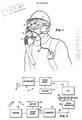
- a user 1 wearing a typical full face mask 2 is shown.
- the full face mask 2 has a regulator 6, breathing tube 5 connected to an air supply (not shown), and a transparent face lens 4.
- the full face mask 2 is provided with a communication device according to the present invention. Only the receiver unit 30 element of the device can be seen mounted outside the face mask 2. It is understood, however, that the transmitter unit is securely mounted within the face mask.
- the communication device is generally described in conjunction with a full face mask, it is contemplated that the invention can be used to provide communication across any clear substrate.
- the communication device is composed of two major parts, a transmitter unit 10 and a receiver unit 30.
- the transmitter unit 10 When in use, the transmitter unit 10 is placed on the side of the clear substrate 25 from which the audible sound 13 to be transmitted originates.
- the receiver unit 30, then, is positioned on the opposite side of the clear substrate 25 in optical relationship with the transmitter unit 10.
- the transmitter unit 10 comprises a microphone 12, signal converting circuit board 14, battery 16, and infra-red transmitter 18.
- the infra-red transmitter 18 is a light emitting diode (LED) 18.
- the microphone 12 picks up the audible sound 13 and sends an electrical signal to the circuit board 14 which is powered by the battery 16.
- the signal from the circuit board 14 is amplified and sent to the infra-red transmitter 18 which emits infra-red light rays 23 that pass through the clear substrate 25.
- the rays 23 are received by the receiver unit 30 positioned on the opposite side of the clear substrate 25.
- the receiver unit 30 includes a receiver 32, which in the embodiment shown is a phototransistor responsive to the infra-red light rays 23. Both the infra-red transmitter 18 and the infra-red receiver 32 are in confronting relationship on opposite sides of the clear substrate 25.
- a signal converting circuit board 34 is responsively coupled to the receiver 32 by way of a shielded cable 31a, 31b and a break-away connector 33. The circuit board 34 is powered by a battery 36. The output from the circuit board 34 is coupled to the speaker 38 which then broadcasts a sound 35 that corresponds to the audible sound 13 of the user.
- the communication unit When used in conjunction with a full face mask, the communication unit will transmit infra-red light rays through the face lens 4 (Fig. 1) of the mask.
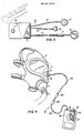
- the transmitter unit 10 with its individual components is shown in more detail in Fig. 3.
- the circuit board 14 is sealed in a transmitter housing 15.
- the microphone 12, infra-red transmitter 18, and battery 16 are connected to the circuit board 14 in the housing 15 by their respective cables 19, 20 and 21.
- Battery cable 21 has a connector 17 for facilitating replacement of the battery 16.
- the components shown can, therefore, be situated to best accommodate the particular use of the transmitter.
- all of the components of the transmitter unit 10 may be waterproofed by any known technique, for example epoxy potting.
- the purpose for having the transmitter components be waterproofed is that if they are mounted in a full face mask 2, they are likely to be subjected to immersion in water. For example, Government regulations normally require that the masks be cleaned after each use. The steps for cleaning often include submerging the mask in water. A transmitter unit mounted in the mask must therefore be able to withstand such procedure.
- the transmitter unit 10 has a timer switch 11 which activates a timer (not shown) within the housing 15.
- the timer which is depicted in Fig. 9 and explained in more detail further below, allows the transmitter unit 10 to operate for a predetermined time period (e.g. 1 hour).
- a predetermined time period e.g. 1 hour.
- a voice activated transmitter unit may draw power from the battery 16 even when the mask is not in use, for example, in response to extraneous noise.
- the user can actuate the switch 11, and the transmitter unit 10 will be operative for one hour. If after an hour, more time is needed, the switch 11 can be actuated again. During other periods when the unit 10 is not in use power is not drawn from the battery 16.
- a one hour time span has been selected for the preferred embodiment because government regulations normally limit to such time worker exposure to hazardous areas. The predominant practice, however, is only one-half hour exposure. Furthermore, most breathing apparatus connected to the full face mask only have one hour supply with a small reserve. Consequently, the present invention contemplates a one hour operative period of time, it being clear that any period of time may be selected. In this way the timer also functions as a warning system to alert the user that he should leave the hazardous area when the speaker 38 no longer broadcasts sound 35.
- Fig. 4 shows the receiver unit 30 in more detail, including its mounting configuration with respect to full face mask 2.
- the infra-red receiver 32 is housed in a protective suction cup 37 that in turn is adhered to the exterior of the lens 4 of the face mask 2.
- a sealant may be used to more securely affix the suction cup 37 to the lens 4.
- the infra-red receiver 32 and suction cup 37 should be placed in confronting relationship with the infra-red transmitter 18 (not shown).
- Cables 31a, 31b and breakaway jacks 33a, 33b connect the infra-red receiver 32 to the receiver housing 39.
- the jacks 33a, 33b When the jacks 33a, 33b are connected, the receiver circuit is complete, and power from the battery 36 supplies the receiver unit 30 thereby placing it in operative condition.
- the receiver unit 30 cannot receive infra-red signals and convert them to audible sounds.
- the breakaway jacks 33a and 33b provide a safety feature. Should the shielded cable 31a, 31b become snagged on an object, the breakaway jacks 33a and 33b will detach and thus allow freedom of movement. Furthermore, the breakaway jacks 33a, 33b will aid in the donning of the mask and associated gear.
- the housing 39 encloses the battery 36, the speaker 38, as well as the circuit board 34 which has a built in locator alarm circuit shown in Fig. 10.
- the user may activate the locator alarm by actuating the switch 40.
- An audible tone will then be placed on the speaker 38 thereby signaling others that the user is in distress.
- Switch 40 toggles the alarm on and off. Because the battery is directly coupled to the circuit board, the locator alarm can be operated even when the jacks 33a and 33b are disconnected.
- the receiver unit 30 has an automatic volume control which functions much like an automatic squelch.
- the circuitry of the receiver unit 30, illustrated in Fig. 10 is designed such that the volume level of the speaker 38 remains constant and undesirable feedback, primarily from the speaker 38, is eliminated.
- the automatic volume control can be set in the field to a desired level after which the circuitry in the receiver unit 30 will automatically maintain the volume level constant. A fuller description of the automatic volume control and other circuitry of the receiver unit 30 is provided further below.
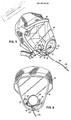
- Fig. 5 illustrates a specific embodiment of the invention wherein the communication unit according to the present invention is mounted to the self-contained breathing apparatus sold under the trademark "SCOTT". For clarity only the transmitter unit 10 and those portions of the receiver unit 30 which are affixed to the full face mask 42 are shown.
- SCOTT self-contained breathing apparatus
- the "SCOTT" mask 42 has a large conical-shaped lens 44 with a regulator 46 mounted at the apex.
- a breathing tube (not shown) connects the regulator to a supply of air.
- the transmitter unit 10 is fitted inside the mask 42 by setting the microphone 12, the transmitter housing 15, the battery 16, and the transmitter 18 in a silicone sealant which is adhered to the inside surface of the lens 44.
- the silicone sealant does not affect the molecular structure of the mask. Any suitable adhesive that does not react with the molecular structure of the mask could be used to affix the transmitter unit 10 thereto.
- the transmitter unit 10 is positioned at a lower region of the lens such that the vision of the user is not obstructed. A positive pressure is maintained within the mask 42, and the overall sealing integrity is not affected.
- the infra-red transmitter 18 emits infra-red light directly through the medium of the lens 44.
- the infra-red receiver 32 is mounted on the exterior of the lens 44 directly opposite the infra-red transmitter 18. When the jack 33a is coupled to the rest of the receiver unit 40 (not shown in Fig. 5, but see Fig. 4), the emitted light rays are received and converted into an audible sound.
- Fig. 6 is a front view of the "SCOTT" mask equipped with the transmitter unit 10 and a portion of the receiver unit 30. As can be seen, the transmitter unit components 12, 15, 16, 18, effectively, are wrapped around the lower portion of the lens 44. In practice, the user will activate the timer switch 11 before donning the mask 42. The user will then have a 1 hour operating period.
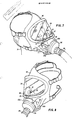
- Fig. 7 and Fig. 8 illustrate another embodiment of the invention wherein the communication unit according to the present invention is mounted to the self-contained breathing apparatus including a face mask 52 sold under the tradename "MSA". For clarity only the transmitter unit 10 mounted within the apparatus is shown.
- the MSA mask 52 is made of a soft neoprene material with a plexiglass face lens 54.
- a breathing tube 55 supplies air from a source (not shown) to a regulator 56. The air then passes through existing internal pockets 53a and 53b to the user 51.
- the transmitter unit's housing 15 and the battery 16 are placed in respective side pockets 53a and 53b. Placement of these components in the pockets 53a and 53b does not affect the positive pressure within the mask nor the normal breathing of the user. Furthermore the sealing integrity of the mask 52 is not compromised.
- the microphone 12 is pinned to excess neoprene seam material 59 in the MSA masks of the type used herein.
- a pin (not shown) connected to the microphone 12 is punched through the excess neoprene material 59 near where the mouth of the user 51 is during use and is held in place on the opposite side by a clasp (not shown).
- Any suitable clip for example an alligator clip, could be used for attaching the microphone 12 to the excess material 59.
- the MSA mask normally is manufactured with a baffle plate 57 attached near a point 55 where a lower portion of the lens 54 joins the neoprene material of the mask 52.
- the infra-red transmitter 18 is mounted to the baffle plate 57 by punching a hole 58 therein and inserting the transmitter 18 through the hole such that the infra-red light is transmitted through the face lens 54.
- the baffle plate 57 is normally biased against the lens 54, and, therefore, maintains the mounted infra-red transmitter 18 in confronting relationship with the receiver 32 (not shown).
- the user 51 can activate the transmitter unit 10 either before or after donning the MSA mask. Because the pocket 53a where the transmitter housing 15 is placed is made from soft neoprene material, the switch 11 can be activated from outside of the mask 52 by pushing on it through the soft neoprene material.
- Fig. 9 is a schematic diagram of the circuitry of the transmitter unit 10.
- a switch activated 1-hour timer 115 which controls the operation of the transmitter unit 10, comprises a momentary switch 111, a capacitor 113, MOSFET 114, diode 112, and capacitor 117.
- the switch 11 on the transmitter unit (Fig. 3) is depressed, the circuit switch 111 momentarily completes the power connection between two series connected 3 volt lithium batteries 126a and 126b and the capacitor 113.
- the momentary connection made by the switch 111 is sufficient to charge the capacitor 113.
- the charge is then sufficient to gate FET 114 on.
- the FET 114 acts as a switch to couple the battery 126a, 126b to the transmitter circuitry 135 via lead 118 for a certain period of time; thereafter the transmitter will shut off when the FET 114 is gated off.
- the diode 112 coupled to the capacitor 113 controls its decay time. The choice of capacitor 113, MOSFET transistor 114, the diode 112 determines the operating time for the transmitter unit.
- the components of the signal converting and transmitting circuitry 135 include a crystal microphone 112 which receives voice sounds 13 of the user and transmits a corresponding audio signal to the remaining circuitry.
- the audio signal is coupled to ceramic coupling capacitor 131.
- the operational amplifier 138 is biased by the input resistors 119 and 124 and the feedback resistor 129.
- the timer 115 provides one input 139 to amplifier 138 via resistor 124 to enable the amplifier 138 while FET 114 is gated on.
- Output capacitor 132 AC couples the outputs signal of the operational amplifier 138 to driver transistor 136 which is appropriately biased by means of biasing resistors 133, 134 and 137.
- An infra-red light emitting diode 128 coupled to the output of the drive 136 emits an infra-red signal 23 corresponding to the original sound signal 13.
- Fig. 10 is a schematic diagram of the circuitry of the receiver unit 30 which has two modes of operation. In the first mode the receiver unit 30 receives and converts infra-red signals 23 to audible sounds 35. In a second mode the receiver unit 30 operates a locator alarm. In the first mode the photo transistor 146 receives the infra-red signal 23 and converts it to an electrical signal which is then applied to the input 159 of operational amplifier 160 via coupling capacitor 154 which filters DC. The operational amplifier 160 amplifies the electrical signal to drive the speaker 143.
- the speaker 143 has parallel RC network including series connected capacitors 172, 176 and resistor 174.
- a feedback loop 161 including capacitor 162 and variable resistor 164 is coupled across the operational amplifier 160.
- the feedback loop 161 controls the tone quality of the speaker 143.
- the variable resistor 164 can be adjusted and set to achieve a desired sound.
- a hole may be formed in the receiver unit housing, adjacent the potentiometer 164, to provide the access needed to make the adjustments desired.
- the receiver circuitry 30 has a negative feedback loop 177 that functions as an autosquelch to automatically maintain the volume of the speaker 143 at a predetermined level, and to eliminate undesirable feedback.
- Transistor 180 drives the circuit loop 177 by amplifying the electrical signal in accordance with the setting of the parallel connected potentiometer 184 and capacitor 186.
- Transistor 188 responsive to the output of the transistor 180, gates field-effect transistor 196 which is coupled to the input 159 of the operational amplifier 160, thereby controlling its operating point such that the volume level remains relatively constant.
- Resistors 178, 182, 190, 192 and capacitor 194 further condition and filter the signal before it is applied to the operational amplifier 160.
- the feedback loop 177 adjusts the corresponding electrical signal to reduce (or increase) the input signal of the operational amplifier 160, which in turn drives the speaker 143.
- the volume level of sound 35 emitted by the speaker 143 therefore, remains constant regardless of the level of the voice input.
- the user can take the unit out to the field and manually adjust the potentiometers 164 and 184 to reach the desired tone and volume levels.
- the electrical signal from the phototransistor 146 is coupled to the remaining circuitry through shielded cable 31a and 31b provided with breakaway jacks 33a and 33b.
- the first jack 33a is a mono jack and the second 33b is a stereo jack. They function as an on/off switch for the receiver unit 30.
- a double pole double throw switch 156 having two contact assemblies 156a and 156b, will be positioned as shown in Fig. 10. Contact 156a is in connection with its right pole, and contact 156b is in connection with its lower pole. The two contacts 156a and 156b are operatively coupled as illustrated by the dotted line 157.
- Contact 156a functions as a monitor for the battery 142. When the jacks 33a and 33b are disconnected the contact 156a is positioned to the left to prevent power from being drawn from the battery 142. When the jacks are connected, contact 156a is positioned to the right in order to allow power to be drawn from the battery 142.
- Contact 156b is operated when the manual locator alarm switch 40 is actuated. However in the normal operating mode i.e. when the alarm is not activated, contact 156b is in the down position as shown in Fig. 10. In this way, the electrical signal from the phototransistor 146 is coupled to operational amplifier 160.
- the second mode of operation for the receiver unit concerns the locator alarm.
- contact 156b moves to engage the upper pole and thereby operatively couple the feedback loop 161 to the operational amplifier 160.
- the feedback loop 161 has a capacitor 166 which causes the noise of the operational amplifier 160 to be AC coupled to its input 159 amplification whereby the speaker 143 is driven to produce a steady tone.
- the present invention provides a simple, yet effective voice communication system whereby a user can communicate across a transparent substrate without materially affecting the substrate.
Landscapes
- Health & Medical Sciences (AREA)
- Pulmonology (AREA)
- General Health & Medical Sciences (AREA)
- Business, Economics & Management (AREA)
- Emergency Management (AREA)
- Physics & Mathematics (AREA)
- Engineering & Computer Science (AREA)
- Acoustics & Sound (AREA)
- Signal Processing (AREA)
- Respiratory Apparatuses And Protective Means (AREA)
- Optical Communication System (AREA)
- Transceivers (AREA)
Applications Claiming Priority (2)
| Application Number | Priority Date | Filing Date | Title |
|---|---|---|---|
| US294000 | 1989-01-05 | ||
| US07/294,000 US4980926A (en) | 1989-01-05 | 1989-01-05 | Voice communication unit |
Publications (2)
| Publication Number | Publication Date |
|---|---|
| EP0377316A2 true EP0377316A2 (fr) | 1990-07-11 |
| EP0377316A3 EP0377316A3 (fr) | 1991-06-12 |
Family
ID=23131472
Family Applications (1)
| Application Number | Title | Priority Date | Filing Date |
|---|---|---|---|
| EP19890313560 Withdrawn EP0377316A3 (fr) | 1989-01-05 | 1989-12-22 | Unité de communication vocale |
Country Status (4)
| Country | Link |
|---|---|
| US (1) | US4980926A (fr) |
| EP (1) | EP0377316A3 (fr) |
| CA (1) | CA2005351C (fr) |
| ZA (1) | ZA899661B (fr) |
Cited By (9)
| Publication number | Priority date | Publication date | Assignee | Title |
|---|---|---|---|---|
| FR2695039A1 (fr) * | 1992-09-01 | 1994-03-04 | Peron Jean Yves | Dispositif de communication adapté à un ensemble respiratoire. |
| WO1997037724A1 (fr) * | 1996-04-04 | 1997-10-16 | Safety Equipment Australia Pty. Ltd. | Interface de communication destinee a un respirateur |
| FR2786107A1 (fr) * | 1998-11-25 | 2000-05-26 | Sextant Avionique | Masque inhalateur d'oxygene avec dispositif de prise de son |
| GB2390979A (en) * | 2002-07-12 | 2004-01-28 | Joseph Anthony Griffiths | Noise damping mask |
| GB2415316A (en) * | 2002-06-05 | 2005-12-21 | Grayling Wireless Inc | Audible and radio communications system for breathing apparatus |
| WO2008095917A1 (fr) * | 2007-02-06 | 2008-08-14 | Fraunhofer-Gesellschaft zur Förderung der angewandten Forschung e. V. | Masque de protection respiratoire avec microphone |
| US7483682B2 (en) | 2004-04-08 | 2009-01-27 | Clearcalm Inc. | Dual-band radio enabled lapel mounted audio and signal handling system and method |
| WO2014184266A1 (fr) * | 2013-05-14 | 2014-11-20 | Elno | Microphone comportant un interrupteur de sourdine, et masque de respiration comprenant un tel microphone |
| EP2915165A4 (fr) * | 2012-10-31 | 2016-06-29 | Vocalzoom Systems Ltd | Système et procédé de détection de signaux acoustiques liés à la parole par l'utilisation d'un microphone laser |
Families Citing this family (35)
| Publication number | Priority date | Publication date | Assignee | Title |
|---|---|---|---|---|
| US5371804A (en) * | 1987-12-18 | 1994-12-06 | Actron Manufacturing Company | Voice transmission system |
| WO1992010046A1 (fr) * | 1990-12-03 | 1992-06-11 | Light Ideas Incorporated | Telephone cellulaire a liaison optique |
| US5224473A (en) * | 1991-03-04 | 1993-07-06 | Bloomfield John W | Retrofitting gas mask voice amplifier unit with easily actuated switch means |
| US5224474A (en) * | 1991-03-04 | 1993-07-06 | Bloomfield John W | Retrofitting gas mask voice amplifier unit with easily actuated switch means |
| JP3208800B2 (ja) * | 1991-08-09 | 2001-09-17 | ソニー株式会社 | マイクロフォン装置及びワイヤレスマイクロフォン装置 |
| US5471658A (en) * | 1993-03-26 | 1995-11-28 | Iacono; Gene A. | Hermetically sealed communication system with rechargeable battery |
| US5428688A (en) * | 1993-03-29 | 1995-06-27 | Audiopack Sounds Systems | Voice transmission system with remote microphone |
| WO1995009676A1 (fr) | 1993-10-01 | 1995-04-13 | Minnesota Mining And Manufacturing Company | Adaptateur de transmission de signaux vocaux destine a un masque respiratoire |
| US5463693A (en) * | 1993-11-10 | 1995-10-31 | Audiopack Sound Systems Inc. | Voice amplification adapter assembly for face mask |
| US5566362A (en) * | 1994-05-03 | 1996-10-15 | Audiopack Sound Systems, Inc. | Wireless voice transmission system |
| US5990793A (en) * | 1994-09-02 | 1999-11-23 | Safety Tech Industries, Inc. | Firefighters integrated communication and safety system |
| US6121881A (en) * | 1994-09-02 | 2000-09-19 | Safety Tech Industries, Inc. | Protective mask communication devices and systems for use in hazardous environments |
| US6430298B1 (en) | 1995-01-13 | 2002-08-06 | Lonnie Joe Kettl | Microphone mounting structure for a sound amplifying respirator and/or bubble suit |
| US5503141A (en) * | 1995-01-13 | 1996-04-02 | Kettl; Lonnie J. | Microphone mounting structure for a sound amplifying respirator |
| US5860417A (en) * | 1995-01-13 | 1999-01-19 | Kettl; Lonnie Joe | Microphone mounting structure for a sound amplifying respirator and/or bubble suit |
| US5552780A (en) * | 1995-03-09 | 1996-09-03 | Siemens Automotive Corporation | Method and apparatus for transmitting coded light through low transmissible materials |
| US5627802A (en) * | 1995-06-19 | 1997-05-06 | Langer Electronics Corp. | Sound amplification system having a submersible microphone |
| USD386499S (en) * | 1995-09-26 | 1997-11-18 | Langer Electronics Corp. | Hydrophone housing |
| US7095981B1 (en) * | 2000-04-04 | 2006-08-22 | Great American Technologies | Low power infrared portable communication system with wireless receiver and methods regarding same |
| GB2371493B (en) * | 2001-01-29 | 2005-02-02 | Davies Ind Comm Ltd | A microphone adaptor for a respirator |
| JP3674533B2 (ja) * | 2001-04-24 | 2005-07-20 | 日本電気株式会社 | 波長多重システムにおけるosc信号のクロック同期監視方法 |
| AU2002305556A1 (en) * | 2001-05-09 | 2002-11-18 | David Cooper | Mask with a built-in microphone |
| JP4264619B2 (ja) * | 2001-10-12 | 2009-05-20 | 山本光学株式会社 | 呼吸用保護具 |
| US20050199663A1 (en) * | 2004-03-05 | 2005-09-15 | Lockheed Martin Corporation | Safety system for a portable data collection device |
| US7342502B2 (en) * | 2005-06-16 | 2008-03-11 | Consort, Llc | Wireless short range communication system |
| CA2525609C (fr) * | 2005-11-04 | 2012-03-20 | Terence A. Ibbetson | Haut-parleur pour systeme de communication |
| US20080037987A1 (en) * | 2006-02-06 | 2008-02-14 | Bradley Albert M | Communication/power network having out-of-band time and control signaling |
| US20070235031A1 (en) * | 2006-03-31 | 2007-10-11 | 3M Innovative Properties Company | Full face respiratory protection device |
| CL2011002875A1 (es) * | 2011-11-15 | 2012-03-30 | Ingenieria Computacion Y Comunicaciones Solunova Ltda | Sistema de comunicacion para mascaras de proteccion respiratoria, que comprende un adaptador de vibracion de voz con alojamiento para un microfono de componentes electronicos, medios de transmision y recepcion conectados entre si en forma alambrica o inalambrica, que permiten la transmision de la voz en forma fluida y clara. |
| US9498658B2 (en) | 2013-02-01 | 2016-11-22 | 3M Innovative Properties Company | Respirator mask speech enhancement apparatus and method |
| US9517366B2 (en) | 2013-02-01 | 2016-12-13 | 3M Innovative Properties Company | Respirator mask speech enhancement apparatus and method |
| US12562267B2 (en) * | 2020-08-11 | 2026-02-24 | Woxx, Inc. | Sound directing device for a mobile telecommunication device having microbial barrier properties |
| US20220142287A1 (en) * | 2020-11-06 | 2022-05-12 | Jeffrey Newton | Lightweight face shield with microphone and speaker |
| US11508390B1 (en) | 2021-05-13 | 2022-11-22 | Sang Ko | Voice transmitter assembly |
| US12033656B2 (en) | 2021-06-19 | 2024-07-09 | Kyndryl, Inc. | Diarisation augmented reality aide |
Family Cites Families (20)
| Publication number | Priority date | Publication date | Assignee | Title |
|---|---|---|---|---|
| US3267414A (en) * | 1963-11-13 | 1966-08-16 | Janus Products Inc | Portable underwater communication unit |
| US3540442A (en) * | 1967-08-10 | 1970-11-17 | Automatic Sprinkler Corp | Face mask microphone mounting |
| DE1905533A1 (de) * | 1969-02-05 | 1970-08-20 | Licentia Gmbh | Verfahren zum Betreiben einer Sprechverbindung |
| US3746789A (en) * | 1971-10-20 | 1973-07-17 | E Alcivar | Tissue conduction microphone utilized to activate a voice operated switch |
| US3867715A (en) * | 1973-11-08 | 1975-02-18 | Us Navy | Underwater communications system |
| US4154981A (en) * | 1977-12-16 | 1979-05-15 | The United States Of America As Represented By The Secretary Of The Navy | Telephone system for diver communication |
| US4229829A (en) * | 1978-03-16 | 1980-10-21 | Grunwald Peter H | Apparatus for wireless transmission of a teaching program in a classroom |
| US4163123A (en) * | 1978-06-19 | 1979-07-31 | Becker William D | Electronic tour guide system |
| US4508936A (en) * | 1980-07-16 | 1985-04-02 | Gentex Corporation | Local external communication system |
| US4491699A (en) * | 1981-04-15 | 1985-01-01 | Nl Industries, Inc. | Communication apparatus for hostile environments |
| US4446375A (en) * | 1981-10-14 | 1984-05-01 | General Electric Company | Optocoupler having folded lead frame construction |
| US4517417A (en) * | 1982-03-25 | 1985-05-14 | Honda Giken Kogyo Kabushiki Kaisha | Communication system for a motor vehicle |
| JPS6068734U (ja) * | 1983-10-18 | 1985-05-15 | 株式会社岩田エレクトリツク | 送受話器 |
| US4620068A (en) * | 1984-06-06 | 1986-10-28 | Remic Corporation | Communication headset |
| US4747158A (en) * | 1985-01-22 | 1988-05-24 | Data Products New England, Inc. | Cordless communications system |
| US4584707A (en) * | 1985-01-22 | 1986-04-22 | Dataproducts New England, Inc. | Cordless communications system |
| FR2584254A1 (fr) * | 1985-06-28 | 1987-01-02 | Braun Bernard | Dispositif emetteur-recepteur pour la communication vocale a courte distance |
| US4685133A (en) * | 1985-09-16 | 1987-08-04 | Inr Technologies, Inc. | Wireless audio transmission system |
| US4750216A (en) * | 1985-10-31 | 1988-06-07 | General Electric Company | Video coupler device |
| US4843640A (en) * | 1986-04-24 | 1989-06-27 | Gte Valeron Corporation | Industrial identification transponder |
-
1989
- 1989-01-05 US US07/294,000 patent/US4980926A/en not_active Expired - Lifetime
- 1989-12-13 CA CA002005351A patent/CA2005351C/fr not_active Expired - Fee Related
- 1989-12-18 ZA ZA899661A patent/ZA899661B/xx unknown
- 1989-12-22 EP EP19890313560 patent/EP0377316A3/fr not_active Withdrawn
Cited By (13)
| Publication number | Priority date | Publication date | Assignee | Title |
|---|---|---|---|---|
| FR2695039A1 (fr) * | 1992-09-01 | 1994-03-04 | Peron Jean Yves | Dispositif de communication adapté à un ensemble respiratoire. |
| WO1994005372A1 (fr) * | 1992-09-01 | 1994-03-17 | Bretagne Radio Communications | Dispositif de communication adapte a un ensemble respiratoire |
| WO1997037724A1 (fr) * | 1996-04-04 | 1997-10-16 | Safety Equipment Australia Pty. Ltd. | Interface de communication destinee a un respirateur |
| FR2786107A1 (fr) * | 1998-11-25 | 2000-05-26 | Sextant Avionique | Masque inhalateur d'oxygene avec dispositif de prise de son |
| WO2000030716A1 (fr) * | 1998-11-25 | 2000-06-02 | Thomsom-Csf Sextant | Masque inhalateur d'oxygene avec dispositif de prise de son |
| US6997178B1 (en) | 1998-11-25 | 2006-02-14 | Thomson-Csf Sextant | Oxygen inhaler mask with sound pickup device |
| GB2415316A (en) * | 2002-06-05 | 2005-12-21 | Grayling Wireless Inc | Audible and radio communications system for breathing apparatus |
| GB2390979A (en) * | 2002-07-12 | 2004-01-28 | Joseph Anthony Griffiths | Noise damping mask |
| US7483682B2 (en) | 2004-04-08 | 2009-01-27 | Clearcalm Inc. | Dual-band radio enabled lapel mounted audio and signal handling system and method |
| WO2008095917A1 (fr) * | 2007-02-06 | 2008-08-14 | Fraunhofer-Gesellschaft zur Förderung der angewandten Forschung e. V. | Masque de protection respiratoire avec microphone |
| EP2915165A4 (fr) * | 2012-10-31 | 2016-06-29 | Vocalzoom Systems Ltd | Système et procédé de détection de signaux acoustiques liés à la parole par l'utilisation d'un microphone laser |
| WO2014184266A1 (fr) * | 2013-05-14 | 2014-11-20 | Elno | Microphone comportant un interrupteur de sourdine, et masque de respiration comprenant un tel microphone |
| FR3005823A1 (fr) * | 2013-05-14 | 2014-11-21 | Elno | Microphone comportant un interrupteur de sourdine, et masque de respiration comprenant un tel microphone |
Also Published As
| Publication number | Publication date |
|---|---|
| US4980926A (en) | 1990-12-25 |
| ZA899661B (en) | 1990-11-28 |
| EP0377316A3 (fr) | 1991-06-12 |
| CA2005351C (fr) | 1999-04-13 |
| CA2005351A1 (fr) | 1990-07-05 |
Similar Documents
| Publication | Publication Date | Title |
|---|---|---|
| US4980926A (en) | Voice communication unit | |
| US6121881A (en) | Protective mask communication devices and systems for use in hazardous environments | |
| US5566362A (en) | Wireless voice transmission system | |
| US4491699A (en) | Communication apparatus for hostile environments | |
| US4620068A (en) | Communication headset | |
| US5426719A (en) | Ear based hearing protector/communication system | |
| US5208867A (en) | Voice transmission system and method for high ambient noise conditions | |
| GB2084428A (en) | Local external communication device for enclosed helmet and mask assembly | |
| US5345509A (en) | Transducer with ear canal pickup | |
| US20030224838A1 (en) | Mask communication system | |
| US5428688A (en) | Voice transmission system with remote microphone | |
| US20050141730A1 (en) | Vibration-based talk-through method and apparatus | |
| AU625941B2 (en) | Communications headset | |
| WO1994005231A9 (fr) | Systeme auditif de protection/communication place sur les oreilles | |
| WO1995013689A1 (fr) | Ensemble adaptateur de transmission vocale | |
| US20050063561A1 (en) | Dual microphone assembly for mask | |
| WO1992009251A1 (fr) | Dispositif de communication permettant de transmettre des informations sonores a un utilisateur | |
| US20050238181A1 (en) | Hearing protector | |
| KR101474519B1 (ko) | 공기 호흡기용 마스크 | |
| US20070049360A1 (en) | Cell phone interface to personal protection device | |
| US20190005804A1 (en) | Alert system for mri technologist and caregiver | |
| US20220387222A1 (en) | Hearing protection device for protection in different hearing situations, controller for such device, and method for switching such device | |
| GB2225958A (en) | Breathing apparatus warning device | |
| US6643373B1 (en) | Speaker volume indicator for telephone handsets | |
| KR200282080Y1 (ko) | 골전도 소자를 이용한 무선 단말기용 핸즈프리 장치 |
Legal Events
| Date | Code | Title | Description |
|---|---|---|---|
| PUAI | Public reference made under article 153(3) epc to a published international application that has entered the european phase |
Free format text: ORIGINAL CODE: 0009012 |
|
| AK | Designated contracting states |
Kind code of ref document: A2 Designated state(s): DE FR GB |
|
| PUAL | Search report despatched |
Free format text: ORIGINAL CODE: 0009013 |
|
| AK | Designated contracting states |
Kind code of ref document: A3 Designated state(s): DE FR GB |
|
| 17P | Request for examination filed |
Effective date: 19911211 |
|
| STAA | Information on the status of an ep patent application or granted ep patent |
Free format text: STATUS: THE APPLICATION IS DEEMED TO BE WITHDRAWN |
|
| 18D | Application deemed to be withdrawn |
Effective date: 19920703 |