EP0377329B1 - Appareil de pompe à chaleur - Google Patents
Appareil de pompe à chaleur Download PDFInfo
- Publication number
- EP0377329B1 EP0377329B1 EP89313661A EP89313661A EP0377329B1 EP 0377329 B1 EP0377329 B1 EP 0377329B1 EP 89313661 A EP89313661 A EP 89313661A EP 89313661 A EP89313661 A EP 89313661A EP 0377329 B1 EP0377329 B1 EP 0377329B1
- Authority
- EP
- European Patent Office
- Prior art keywords
- refrigerant
- fractioning
- separating device
- restrictor
- reservoir
- Prior art date
- Legal status (The legal status is an assumption and is not a legal conclusion. Google has not performed a legal analysis and makes no representation as to the accuracy of the status listed.)
- Expired - Lifetime
Links
Images


Classifications
-
- F—MECHANICAL ENGINEERING; LIGHTING; HEATING; WEAPONS; BLASTING
- F25—REFRIGERATION OR COOLING; COMBINED HEATING AND REFRIGERATION SYSTEMS; HEAT PUMP SYSTEMS; MANUFACTURE OR STORAGE OF ICE; LIQUEFACTION SOLIDIFICATION OF GASES
- F25B—REFRIGERATION MACHINES, PLANTS OR SYSTEMS; COMBINED HEATING AND REFRIGERATION SYSTEMS; HEAT PUMP SYSTEMS
- F25B13/00—Compression machines, plants or systems, with reversible cycle
-
- F—MECHANICAL ENGINEERING; LIGHTING; HEATING; WEAPONS; BLASTING
- F25—REFRIGERATION OR COOLING; COMBINED HEATING AND REFRIGERATION SYSTEMS; HEAT PUMP SYSTEMS; MANUFACTURE OR STORAGE OF ICE; LIQUEFACTION SOLIDIFICATION OF GASES
- F25B—REFRIGERATION MACHINES, PLANTS OR SYSTEMS; COMBINED HEATING AND REFRIGERATION SYSTEMS; HEAT PUMP SYSTEMS
- F25B41/00—Fluid-circulation arrangements
- F25B41/20—Disposition of valves, e.g. of on-off valves or flow control valves
-
- F—MECHANICAL ENGINEERING; LIGHTING; HEATING; WEAPONS; BLASTING
- F25—REFRIGERATION OR COOLING; COMBINED HEATING AND REFRIGERATION SYSTEMS; HEAT PUMP SYSTEMS; MANUFACTURE OR STORAGE OF ICE; LIQUEFACTION SOLIDIFICATION OF GASES
- F25B—REFRIGERATION MACHINES, PLANTS OR SYSTEMS; COMBINED HEATING AND REFRIGERATION SYSTEMS; HEAT PUMP SYSTEMS
- F25B41/00—Fluid-circulation arrangements
- F25B41/40—Fluid line arrangements
-
- F—MECHANICAL ENGINEERING; LIGHTING; HEATING; WEAPONS; BLASTING
- F25—REFRIGERATION OR COOLING; COMBINED HEATING AND REFRIGERATION SYSTEMS; HEAT PUMP SYSTEMS; MANUFACTURE OR STORAGE OF ICE; LIQUEFACTION SOLIDIFICATION OF GASES
- F25B—REFRIGERATION MACHINES, PLANTS OR SYSTEMS; COMBINED HEATING AND REFRIGERATION SYSTEMS; HEAT PUMP SYSTEMS
- F25B9/00—Compression machines, plants or systems, in which the refrigerant is air or other gas of low boiling point
- F25B9/002—Compression machines, plants or systems, in which the refrigerant is air or other gas of low boiling point characterised by the refrigerant
- F25B9/006—Compression machines, plants or systems, in which the refrigerant is air or other gas of low boiling point characterised by the refrigerant the refrigerant containing more than one component
-
- F—MECHANICAL ENGINEERING; LIGHTING; HEATING; WEAPONS; BLASTING
- F25—REFRIGERATION OR COOLING; COMBINED HEATING AND REFRIGERATION SYSTEMS; HEAT PUMP SYSTEMS; MANUFACTURE OR STORAGE OF ICE; LIQUEFACTION SOLIDIFICATION OF GASES
- F25B—REFRIGERATION MACHINES, PLANTS OR SYSTEMS; COMBINED HEATING AND REFRIGERATION SYSTEMS; HEAT PUMP SYSTEMS
- F25B2600/00—Control issues
- F25B2600/25—Control of valves
- F25B2600/2519—On-off valves
Definitions
- the present invention relates to an improvement in a heat pump apparatus of a type using nonazeotropic mixed refrigerant and capable of varying the composition of the mixed refrigerant by reserving high boiling point refrigerant through separation of the refrigerant's components.
- a heat pump apparatus of a type using nonazeotropic mixed refrigerant and capable of varying the composition of the mixed refrigerant by reserving high boiling point refrigerant through separation of the refrigerant's components.
- Figure 6 shows an apparatus arranged to use nonazeotropic mixed refrigerant and capable of varying the composition of the mixed refrigerant by reserving high boiling point refrigerant through separation of the refrigerant's components.
- reference numeral 1 represents a compressor
- 2 represents a condenser
- 3 represents a main restrictor
- 4 represents an evaporator.
- the main circuit of the heater apparatus is formed by connecting the above-described elements.
- Reference numeral 5 represents a fractioning/separating device filled with filler. An upper portion of the fractioning/separating device 5 is connected to an outlet port of the condenser 2 via a pipe 6 and also connected to an inlet port of the evaporator 4 via an auxiliary restrictor 7.
- a reservoir 8 is disposed below the fractioning/separating device 5, the bottom of the reservoir 8 being connected to the auxiliary restrictor 7 via a valve 9.
- a heater 10 is disposed in the reservoir 8.
- the heater 10 is not operated.
- the reservoir 8 acts to reserve excess refrigerant when valve 9 is closed, and discharges a portion of refrigerant to the evaporator 4 via the auxiliary restrictor 7 when valve 9 is opened, thereby not causing any change in the composition of the refrigerant to take place. Therefore, the main circuit is operated while maintaining the composition of the enclosed mixed-refrigerant enriched with high boiling point refrigerant.
- the heater 10 is operated and the low boiling point refrigerant in the refrigerant contained in the reservoir 8 is, in the main, evaporated, the evaporated low boiling point refrigerant then moving upwards through the fractioning/separating device 5 when the valve 9 is closed.
- liquid refrigerant is supplied from the outlet port of the condenser 2 via the pipe 6 so that fractioning takes place in the fractioning/separating device 5 due to a gas-liquid contact.
- the density of the low boiling point refrigerant in the gas which is moving upwards is raised and the density of the high boiling point refrigerant in the liquid moving downwards is also raised.
- high boiling point refrigerant in the form of a condensed liquid is reserved in the reservoir 8.
- the gas which is moving upwards and which is enriched with low boiling point refrigerant is introduced into the evaporator 4 via the auxiliary restrictor 7. Therefore, the main circuit can be operated while maintaining the composition of the refrigerant enriched with low boiling point refrigerant.
- the apparatus is operated while maintaining the composition of the enclosed refrigerant enriched with high boiling point refrigerant whose condensing pressure is low so as to improve the reliability of the compressor or the like.
- the apparatus is operated while maintaining the composition of the refrigerant enriched with low boiling point refrigerant which exhibits excellent heating performance.
- the heat pump apparatus of the type described above is operated with the pressure of its fractioning/separating device as high as the pressure in the main circuit, the separating performance of the fractioning/separating device has been found to be insufficient. That is, it is known that the performance of the fractioning/separating device can be improved by raising the velocity of the gas which moves upwards in the fractioning/separating device. If separation is conducted at high pressure as described above, the specific volume of the gas generated in the reservoir due to heat applied from the heater is reduced, causing the velocity of the gas in the fractioning/separating device to be reduced. Therefore, the apparatus of the type described above suffers from insufficient separating performance. In order to overcome this insufficiency the heating capability of the heater in the conventional apparatus has been increased. This leads to a reduction in performance. Furthermore, if separation is conducted at high pressure, the saturated temperature of the refrigerant in the reservoir is raised excessively, causing problems in terms of the heat resistance of the devices and unnecessary heat radiation to occur.
- United States patent specification US-A-4913714 discloses an apparatus including a fractioning/separating device having a reservoir within an upper portion thereof, the inside of which is cooled by reducing the pressure of coolant in a lower portion of the fractioning/separating device.
- the lower portion of the fractioning/separating device is not heated since heating would have no effect.
- coolant having a high boiling point cannot be reserved.
- coolant is introduced into the fractioning/separating device by an inlet located generally at the centre of the device. Accordingly, the apparatus disclosed in this specification cannot be incorporated in the apparatus arrangements of the present invention.
- An object of the present invention is to provide a refrigerating cycle structure capable of conducting high performance separation with a reduced quantity of applied heat and capable of being used even if the load or the temperature changes excessively.
- a heat pump apparatus comprising a main heat pump circuit containing nonazeotropic mixed refrigerant, said circuit consists of a compressor, a four-way valve, a utilization side heat-exchanger, a main restrictor, a heat source side heat-exchanger, a fractioning/separating device, a reservoir and a heat source, characterised in that an upper portion of said fractioning/separating device is connected to a pipe disposed between said utilization side heat-exchanger and said main restrictor via a parallel circuit of a first auxiliary restrictor and a first check valve, which allows only a stream discharged from said fractioning/separating device to flow therethrough, and said upper portion thereof is also connected to another pipe between the heat source side heat-exchanger and said main restrictor via a parallel circuit of a second auxiliary restrictor and a second check valve which allow only a stream discharged from said fractioning/separating device to flow therethrough.
- the apparatus is characterised in that an upper portion of said fractioning/separating device is connected to a pipe disposed between said utilization side heat-exchanger and said main restrictor via a first auxiliary restrictor, and said upper portion is connected to an inlet port of a first check valve which allows only a stream discharged from said fractioning/separating device to flow therethrough, an outlet port of said first check-valve is connected to a pipe between said four-way valve and said utilization side heat-exchanger, and said upper portion of said fractioning/separating device is also connected to a pipe between said heat source side-heat exchanger and said main restrictor via a second auxiliary restrictor, said upper portion is connected to an inlet port of a second check valve which allows only a stream discharged from said fractioning/separating device to flow therethrough, and an outlet port of said second check valve is connected to a pipe between the four-way valve and said heat source side heat-exchanger.
- Fig. 1 is a view which illustrates an embodiment of a heat pump apparatus.
- reference numeral 11 represents a compressor
- 12 represents a utilization side heat exchanger (a condenser)
- 13 represents a restrictor, which are sequentially connected via pipes.
- Reference numeral 14 represents a heat source side heat exchanger (an evaporator), and 15 represents a fractioning/separating device filled with filler.
- An upper portion of the fractioning/separating device 15 is connected to an outlet port of the restrictor 13, the upper portion also being connected to an inlet port of the heat source side heat exchanger 14.
- an outlet port of the heat source side heat exchanger 14 and the compressor 11 are connected to each other.
- the main circuit of the heat pump is constituted.
- a reservoir 16 and a heater 17 are disposed below the fractioning/separating device 15, the reservoir 16 having a lower portion connected to the inlet port of the heat source side heat exchanger 14 via a valve 18.
- the structure is arranged such that refrigerant in the reservoir 16 is heated by the heater 17.
- refrigerant discharged from the restrictor 13 is introduced into the reservoir 16 via the fractioning/separating device 15 by opening valve 18, the reservoir 16 reserving excess refrigerant.
- Refrigerant which has not been reserved reaches the heat source side heat exchanger 14 via the valve 18.
- the main circuit is caused to be operated while maintaining the mixed refrigerant enriched with high boiling point refrigerant with composition the same as that when it was first enclosed.
- a separation mode the valve 18 is closed and the heater 17 is operated.
- low boiling point refrigerant from the liquid refrigerant in reservoir 16 is mainly evaporated, the evaporated refrigerant then moving upwards in the fractioning/separating device 15.
- two-phase refrigerant consisting of liquid and gas is supplied from the outlet port of the restrictor 13 to the upper portion of the fractioning/separating device 15. A portion of the thus supplied liquid refrigerant moves downward in the fractioning/separating device 15. Then, the liquid refrigerant undergoes a gas-liquid contact with gas which is moving upwards, causing fractioning to take place.
- the reservoir 16 reserves high boiling point refrigerant in the form of condensed liquid.
- the gas enriched with low boiling point refrigerant which has moved upwards is mixed with the residual portion of the supplied refrigerant before being introduced into the heat source side heat exchanger 14.
- the main circuit can be operated while maintaining the composition of the mixed refrigerant enriched with low boiling point refrigerant.
- the pressure in the fractioning/separating device 15 is arranged to be as low as the pressure in the main circuit, the specific volume of gas generated in the reservoir 16 due to the heat from the heater 17 is large enough, and the velocity of the gas which is moving upward in the fractioning/separating device 15 is thereby increased. As a result, gas-liquid contact is promoted, causing the separating performance of the fractioning/separating device 15 to be improved. Therefore, the density of the high boiling point refrigerant reserved in the reservoir 16 can be significantly raised. Since the composition of the refrigerant in the main circuit becomes a composition enriched with low boiling point refrigerant which has a significant heating performance, the main circuit can satisfactorily cope with an increase in load.
- the saturation temperature for the refrigerant in the reservoir 16 can be lowered, and the heat radiation from the heater 17 can be reduced.
- the composition of the refrigerant in the main circuit can be significantly varied by simply operating the valve 18 and the heater 17. Therefore, the composition of the refrigerant can be easily controlled so as to cope with the magnitude of load applied. As a result, the range in which performance can be varied can be broadened.
- the restrictor 13 and the heat source side heat exchanger 14 are connected to each other via the upper portion of the fractioning/separating device 15 according to this embodiment, the restrictor 13 may be directly connected to the heat source side heat exchanger 14 via another pipe. In this case, only liquid refrigerant which moves downwards in the fractioning/separating device 15 is introduced into the upper portion of the fractioning/separating device 15, causing fractioning to occur. The residual portion of the refrigerant is directly introduced into the heat source side heat exchanger 14. As a result, fractioning can be conducted without affecting the gas-liquid contact taking place in the fractioning/separating device 15.
- nonazeotropic mixed refrigerant as used in this embodiment is composed of R22, which has been mixed in a composition in which the vapour pressure becomes substantially the same as that of R12 and having a boiling point higher than that of R22, the refrigerant can be fractioned and separated in the heat pump apparatus. Therefore, the vapour pressure can be lowered by using the mixed refrigerant as it is in the case where the condensing temperature is at a high level, while the refrigerant, since having a higher boiling point than that of R22, is separated in the case where the operation temperature is low, thereby allowing high heating performance to be realized.
- Refrigerants to be mixed with R22 and having a boiling point higher than that of R22 are, for example:- R134a (-26.5°C), R152a (-25.0°C), R134 (-19.7°C), R124 (-12.0°C), R142b (-9.8°C), RC318 (-5.8°C), R143 (5.0°C), R123 (27.1°C) , R123a (28.2°C), and R141b (32.0°C), which provide a limited possibility of destroying ozone layers and which form nonazeotropic mixed refrigerant together with R22.
- the vapour pressure be substantially equal to that of R12 in the case where the condensing temperature is at a high level.
- the range of the composition of the mixed refrigerant can be simply specified in accordance with a method described with reference to Fig. 2.
- the heater 17 may be activated for certain time periods and thereafter only activation of the heater 17 may be stopped while operating the apparatus.
- the high boiling point refrigerant in the reservoir 16 is cooled while maintaining its density and is reserved in the reservoir 16 as supercooled liquid, the composition enriched with the low boiling point refrigerant can be retained in the main circuit. Therefore, the quantity of heat required for the heater 17 to conduct the separating action can be reduced.
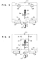
- Fig. 3 is a view which illustrates an embodiment of the heat pump apparatus according to the present invention and structured so as to conduct the switching between heating and cooling operations.
- reference numeral 20 represents a compressor
- 21 represents a four-way valve
- 22 represents a utilisation side heat exchanger
- 23 represents a main restrictor
- 24 represents a heat source side heat exchanger.
- the main circuit of the heat pump apparatus according to this embodiment is formed by connecting the above-described elements via pipes.
- Reference numeral 25 represents a fractioning/separating device filled with filler, the fractioning/separating device 25 having an upper portion connected to a pipe arranged between the utilization side heat exchanger 22 and the main restrictor 23 via a parallel circuit consisting of a first auxiliary restrictor 26 and a first check valve 27.
- the upper portion of the fractioning/separating device 25 is connected to a pipe arranged between the main restrictor 23 and the heat source side heat exchanger 24 via a parallel circuit consisting of a second auxiliary restrictor 28 and a second check valve 29.
- a reservoir 30 is disposed below the fractioning/separating device 25, the lower portion of the reservoir 30 being connected to a pipe arranged between the main restrictor 23 and the heat source side heat exchanger 24 via a valve 31 and a third check valve 32.
- the lower portion of the reservoir 30 is connected to a pipe arranged between the main restrictor 23 and the utilization side heat exchanger 22 via the valve 31 and a fourth check valve 33.
- the structure is so arranged that refrigerant in the reservoir 30 is heated by a heater 34.
- a portion of refrigerant discharged from the utilization side heat exchanger 22 is introduced into the main restrictor 23 by opening the valve 31, the refrigerant thus introduced being then constricted to a low pressure level before being introduced into the heat source side heat exchanger 24.
- the residual portion of the liquid refrigerant passes through the first auxiliary restrictor 26 during which liquid refrigerant is constricted to a low pressure level before being allowed to branch above the fractioning/separating device 25.
- a portion of the liquid refrigerant passes through the second check valve 29 before being introduced into the heat source side heat exchanger 24, while the residual portion is introduced into the reservoir 30 at which excess refrigerant is reserved.
- the refrigerant passes through the valve 31 and the third check valve 32 before being introduced into the heat source side heat exchanger 24.
- the main circuit is operated while maintaining the composition of the mixed refrigerant enriched with high boiling point refrigerant which is the state in which the refrigerant was first enclosed.
- the valve 31 is closed and the heater 34 is operated.
- low boiling point refrigerant of the mixed refrigerant in the reservoir 30 is mainly evaporated, the evaporated refrigerant then moving upwards in the fractioning/separating device 25.
- two-phase refrigerant consisting of liquid and gas is supplied from the outlet point of the first auxiliary restrictor 26 to the upper portion of the fractioning/separating device 25. A portion of the thus supplied liquid refrigerant moves downward in the fractioning/separating device 25. Then, the liquid refrigerant undergoes a gas-liquid contact with gas which is moving upwards, causing fractioning to take place.
- the reservoir 30 reserves high boiling point refrigerant as a condensed liquid.
- the gas enriched with low boiling point refrigerant which has moved upwards is mixed with a portion of the supplied refrigerant before passing through the second check valve 29. Then, it is introduced into the heat source side heat exchanger 24. As a result, the main circuit is operated while maintaining the composition of the mixed refrigerant enriched with low boiling point refrigerant.
- the pressure in the fractioning/separating device 25 is arranged to be as low as the pressure in the main circuit, the specific volume of gas generated is large, and the velocity of the gas which is upward moving in the fractioning/separating device 25 to be thereby increased. As a result, the gas-liquid contact is promoted, causing the separating performance of the fractioning/separating device 25 is improved. Therefore, the density of the high boiling point refrigerant reserved in the reservoir 30 can be significantly raised. Since the composition of the refrigerant in the main circuit becomes a composition enriched with low boiling point refrigerant which has a significant heating performance, the main circuit can satisfactorily cope with an increase in heating load.
- the valve 31 In the separation mode at the time of the cooling operation, the valve 31 is closed and the heater 34 is not operated. As a result, low boiling point refrigerant from the mixed liquid refrigerant in the reservoir 30 is mainly evaporated, the evaporated refrigerant then moving upwards in the fractioning/separating device 25. At this time, two phase refrigerant consisting of liquid and gas is supplied from the outlet port of the second auxiliary restrictor 28 to the upper portion of the fractioning/separating device 25. Then, the liquid refrigerant undergoes a gas-liquid contact with gas which is moving upwards, causing fractioning to take place. As a result, the main circuit is operated while maintaining the composition of the mixed refrigerant enriched with low boiling point refrigerant similar to the case of the heating operation, the composition exhibiting excellent cooling performance. Therefore, the apparatus can cope with an increase in the load.
- the composition of the refrigerant in the main circuit can be significantly varied by simply operating the valve 31 and the heater 34. Therefore, the composition of the refrigerant can be easily controlled so as to cope with the magnitude of the load applied. As a result, the range in which the performance can be varied can be broadened.
- Fig. 4 is a view which illustrates another embodiment of the heat pump apparatus according to the present invention structured so as to conduct switching between the heating and cooling operations. Like elements as those shown in Fig. 3 are given like reference numerals.
- the upper portion of the fractioning/separating device 25 in connected to a pipe arranged between the main restrictor 23 and the utilization side heat exchanger 22 via a first auxiliary resistor 35.
- the upper portion is also connected to a pipe arranged between the four-way valve 21 and the utilization side heat exchanger 22 via a first check valve 36.
- the upper portion of the fractioning/separating device 25 is connected to a pipe arranged between the heat source side heat exchanger 24 and the main restrictor 23 via a second auxiliary restrictor 37.
- the upper portion is also connected to a pipe arranged between the four-way valve 21 and the heat source side heat exchanger 24 via a second check valve 38.
- refrigerant discharged from the first auxiliary restrictor 35 or the second auxiliary restrictor 37 passes through the fractioning/separating device 25 before being introduced into the reservoir by opening the valve 31.
- the excess refrigerant is reserved in the reservoir 30.
- the refrigerant then passes through the valve 31 and the third check valve 32 or the fourth check valve 33 before passing through the main circuit. Therefore, the main circuit can be operated while maintaining the mixed composition of refrigerant enriched with high boiling point which is as it was when first enclosed.
- the valve 31 In the separation mode at the time of the heating operation, the valve 31 is closed. Since the fraction at this time is conducted at a low pressure in similar manner to the apparatus shown in Fig. 3, high performance separation can be conducted. Gas generated from the liquid refrigerant in the reservoir 30 due to the heat supplied from the heater 34 moves upwards in the fractioning/separating device 25 and is sucked by the compressor 20 after passing through the second check valve 38 and the four-way valve 21. As a result, the pressure loss which occurs in the heat source side heat exchanger 24 can be reduced so that the composition of the refrigerant in the main circuit can be made to be a composition enriched with low boiling point refrigerant while performance is maintained at a high level.
- the valve 31 In the separation mode at the time of the cooling operation, the valve 31 is similarly closed. Since fractioning can be similarly conducted at a low pressure, high performance separation can be conducted. Gas generated from the liquid refrigerant in the reservoir 30 due to the heat supplied from the heater 34 moves upwards in the fractioning/separating device 25 and is sucked by the compressor 20 after passing through the first check valve 36 and the four-way valve 21. As a result, the pressure loss which occurs in the utilisation side heat exchanger 22 serving as a heat source side heat-exchanger can be reduced so that the composition of the refrigerant in the main circuit can be made to be a composition enriched with low boiling point refrigerant while performance is maintained at a high level.
- the composition of refrigerant in the main circuit can be significantly varied by conducting the separation at a low pressure in both heating and cooling operations simply by operating the valve 31 and the heater 34. Furthermore, gas generated in the reservoir 30 can be directly sucked by the compressor 20. As a result, the operation provides a high performance.
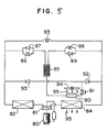
- Fig. 5 is a view which illustrates the structure of a heat pump apparatus according to the present invention and structured so as to conduct switching between heating and cooling operations.
- reference numeral 80 represents a compressor
- 81 represents a four-way valve
- 82 represents a utilisation side heat exchanger
- 83 represents a main restrictor
- 84 represents a heat source side heat exchanger.
- the main circuit of the heat pump apparatus according to this embodiment is formed by connecting the above-described elements.
- Reference numeral 85 represents a fractioning/separating device filled with filler.
- the upper portion of the fractioning/separating device 85 is connected to a pipe arranged between the utilization side heat exchanger 82 and the main restrictor 83 via a parallel circuit formed by a first auxiliary restrictor 86 and a first check valve 87.
- the upper portion of the fractioning/separating device 85 is connected to a pipe arranged between the main restrictor 83 and the heat source side heat exchanger 84 via a parallel circuit formed by a second auxiliary restrictor 88 and a second check valve 89.
- a reservoir 90 is disposed below the fractioning/separating device 85. The lower portion of the reservoir 90 is connected to the pipe arranged between the main restrictor 83 and the heat source side heat exchanger 83 via a valve 91 and a third check valve 92.
- the lower portion is also connected to the pipe arranged between the main restrictor 83 and the utilization side heat exchanger 82 via the valve 91 and a fourth check valve 93.
- the reservoir 90 is structured so as to exchange heat to and from the ambient air 95 blown by a fan 94 and serving as the heat source of the heat source side heat exchanger 84.
- refrigerant discharged from the second auxiliary restrictor 88 passes through the fractioning/separating device 85 before being introduced into the reservoir in which the excess portion of the refrigerant is reserved.
- the residual refrigerant passes through the valve 91 and the fourth check valve 93 before being introduced into the utilization side heat exchanger 82.
- the main circuit is operated with maintaining the composition of mixed refrigerant enriched with high boiling point refrigerant which is in the state as when the refrigerant was first enclosed.
- the valve 91 In the separation mode at the time of the heating operation, the valve 91 is closed. Since the temperature of the refrigerant in the reservoir 90 is substantially the same as the that at an inlet port of the heat source side heat exchanger 84, heat is transmitted from the high temperature ambient air 95 supplied by the fan 94, to the reservoir 90. As a result, low boiling point refrigerant of the mixed liquid refrigerant in the reservoir 90 is mainly evaporated so that the evaporated refrigerant moves upwards in the fractioning/separating device 85. At this time, two-phase refrigerant consisting of liquid and gas is supplied from the outlet port of the first auxiliary restrictor 86 to the upper portion of the fractioning/separating device 85.
- the main circuit can be operated with maintaining the composition of mixed refrigerant enriched with low boiling point refrigerant.
- the pressure in the fractioning/separating device 85 is arranged to be a low pressure, the separating performance can be improved.
- the ambient air 95 is used as the heat source, the heating performance does dot deteriorate.
- the composition of the refrigerant can be varied with a high performance being maintained.
- the apparatus can satisfactorily cope with an increase in load.
- the quantity of refrigerant to be circulated is reduced due to the reduction in the load, evaporation temperature is raised, causing the quantity of heat supplied to the reservoir 90 to be reduced.
- the separation action cannot be promoted, causing the composition of refrigerant in the main circuit to become a composition enriched with high boiling point refrigerant having limited heating performance.
- the apparatus can sufficiently cope with a decrease in the load.
- the valve 91 In the separation mode at the time of the cooling operation, the valve 91 is also closed. Since temperature of refrigerant in the reservoir 90 is substantially equal to that at the inlet port of the utilization side heat exchanger 82 in the main circuit at this time, heat is transmitted from the high temperature ambient air 95 supplied by the fan 94, to the reservoir 90. As a result, low boiling point refrigerant of the mixed liquid refrigerant in the reservoir 90 is mainly evaporated so that the evaporated refrigerant moves upwards in the fractioning/separating device 85. At this time, two-phase refrigerant consisting of liquid and gas is supplied from the outlet port of the second auxiliary restrictor 88 to the upper portion of the fractioning/separating device 85.
- the portion of liquid refrigerant of the supplied refrigerant moves downwards in the fractioning/separating device 85 before being subjected to a gas-liquid contact with the gas which is moving upwards, causing fractioning to take place.
- the main circuit can be operated while maintaining the composition of mixed refrigerant enriched with low boiling point refrigerant in similar manner to the heating operation.
- the fractioning/separating device 85 is operated at a low pressure, excellent separating performance can be obtained.
- the composition of refrigerant necessary to cope with a change in the load can be obtained by adjusting the quantity of refrigerant which passes through the main circuit.
- valve 91 In order to restore the composition of refrigerant in the main circuit, it is necessary for the valve 91 to be opened in both heating and cooling modes to enable the high boiling point refrigerant in the reservoir 90 to be mixed with refrigerant in the main circuit and thereby the composition of refrigerant in the main circuit can be restored to the state when the refrigerant was first enclosed.
- the composition of refrigerant in the main circuit can be significantly varied by conducting separation at a pressure as low as that of the main circuit in both heating and cooling modes, the variation of the composition being capable of maintaining high performance without deterioration in heating and cooling performance. Furthermore, the composition of refrigerant corresponding to the magnitude of the load can be easily controlled in accordance with change in the quantity of refrigerant to be circulated. As a result, the range in which performance can be varied can be broadened.
Landscapes
- Engineering & Computer Science (AREA)
- Physics & Mathematics (AREA)
- Mechanical Engineering (AREA)
- Thermal Sciences (AREA)
- General Engineering & Computer Science (AREA)
- Compression-Type Refrigeration Machines With Reversible Cycles (AREA)
Claims (7)
- Appareil de pompe à chaleur comprenant :
un circuit principal de pompe à chaleur contenant un mélange réfrigérant non-azéotrope, ledit circuit comportant un compresseur (20, 80), un distributeur à quatre orifices (21, 81), un échangeur thermique (22, 82) situé du côté utilisation, un étranglement principal (23, 83), un échangeur thermique (24, 84) situé du côté source de chaleur, un dispositif de fractionnement/séparation (25, 85), un réservoir (30, 90) et une source de chaleur (34,[90, 94]), caractérisé en ce qu'une partie supérieure dudit dispositif de fractionnement/séparation est reliée à une conduite installée entre ledit échangeur thermique (22, 82) situé du côté utilisation et ledit étranglement principal (23, 83) par l'intermédiaire d'un circuit parallèle comprenant un premier étranglement auxiliaire (26, 86) et un premier clapet de retenue (27, 87) qui se laisse uniquement traverser par un flux sortant dudit dispositif de fractionnement/séparation (25, 85), et ladite partie supérieure est également reliée à une autre conduite installée entre l'échangeur thermique (24, 84) situé du côté source de chaleur et ledit étranglement principal (23, 83) par l'intermédiaire d'un circuit parallèle comprenant un second étranglement auxiliaire (28, 88) et un second clapet de retenue (29, 89) qui se laisse uniquement traverser par un flux sortant dudit dispositif de fractionnement/séparation (25, 85). - Appareil de pompe à chaleur comprenant :
un circuit principal de pompe à chaleur contenant un mélange réfrigérant non-azéotrope, ledit circuit comportant un compresseur (20), un distributeur à quatre orifices (21), un échangeur thermique (22) situé du côté utilisation, un étranglement principal (23), un échangeur thermique (24) situé du côté source de chaleur, un dispositif de fractionnement/séparation (25), un réservoir (30) et une source de chaleur (34), caractérisé en ce qu'une partie supérieure dudit dispositif de fractionnement/séparation (25) est reliée à une conduite installée entre ledit échangeur thermique (22) situé du côté utilisation et ledit étranglement principal (23) par l'intermédiaire d'un premier étranglement auxiliaire (35), et la partie supérieure dudit dispositif de fractionnement/séparation (25) est également reliée à un orifice d'entrée d'un premier clapet de retenue (36) qui se laisse traverser uniquement par un flux sortant dudit dispositif de fractionnement/séparation, un orifice de sortie dudit premier clapet de retenue (36) est relié à une conduite montée entre ledit distributeur à quatre orifices (21) et ledit échangeur thermique (22) situé du côté utilisation, et en ce que ladite partie supérieure dudit dispositif de fractionnement/séparation est également reliée à une conduite installée entre ledit échangeur thermique (24) situé du côté source de chaleur et ledit étranglement principal (23) par l'intermédiaire d'un second étranglement auxiliaire (37), la partie supérieure dudit dispositif de fractionnement/séparation (25) est reliée à un orifice d'entrée d'un second clapet de retenue (38) qui se laisse uniquement traverser par un flux sortant dudit dispositif de fractionnement/séparation, et un orifice de sortie dudit second clapet de retenue (38) est relié à une conduite montée entre le dirtibuteur à quatre orifices (21) et ledit échangeur thermique (24) situé du côté source de chaleur. - Appareil de pompe à chaleur selon la revendication 1 ou 2, caractérisé en ce que ledit réservoir (30, 90) est relié à une conduite du côté basse pression dans ledit circuit principal de pompe à chaleur par l'intermédiaire d'une vanne d'arrêt (31, 91).
- Appareil de pompe à chaleur selon l'une quelconque des revendications précédentes, caractérisé en ce que la source de chaleur est un dispositif de chauffage (34) et en ce que le réservoir (30) et le dispositif de chauffage (34) sont installés au-dessous du dispositif de fractionnement/séparation (25).
- Appareil de pompe à chaleur selon la revendication 4, caractérisé en ce que ledit dispositif de chauffage (34) sert de source de chaleur pour ledit échangeur de chaleur (22) situé du côté utilisation ou pour ledit échangeur thermique (24) situé du côté source de chaleur dans ledit circuit principal de pompe à chaleur.
- Appareil de pompe à chaleur selon l'une quelconque des revendications précédentes, caractérisé en ce que ledit mélange réfrigérant non-azéotrope est constitué de R22 et d'un réfrigérant ayant un point d'ébullition supérieur à celui du R22, qui sont mélangés de manière à obtenir une pression de vapeur sensiblement égale à celle de R12.
- Appareil de pompe à chaleur selon la revendication 6, caractérisé en ce qu'un réfrigérant contenant au moins un constituant choisi dans le groupe comprenant R134a, R152a, R134, R124, R142b, RC318, R143, R123, R123a et R141b est utilisé comme réfrigérant dont le point d'ébullition est supérieur à celui de R22.
Priority Applications (1)
| Application Number | Priority Date | Filing Date | Title |
|---|---|---|---|
| EP92115912A EP0518394B1 (fr) | 1988-12-28 | 1989-12-28 | Appareil de pompe à chaleur |
Applications Claiming Priority (6)
| Application Number | Priority Date | Filing Date | Title |
|---|---|---|---|
| JP63334451A JP2512127B2 (ja) | 1988-12-28 | 1988-12-28 | ヒ―トポンプ装置 |
| JP334451/88 | 1988-12-28 | ||
| JP58325/89 | 1989-03-10 | ||
| JP1058325A JPH0739889B2 (ja) | 1989-03-10 | 1989-03-10 | ヒートポンプ装置 |
| JP1087620A JPH02267473A (ja) | 1989-04-06 | 1989-04-06 | 冷凍サイクル装置 |
| JP87620/89 | 1989-04-06 |
Related Child Applications (2)
| Application Number | Title | Priority Date | Filing Date |
|---|---|---|---|
| EP92115912A Division EP0518394B1 (fr) | 1988-12-28 | 1989-12-28 | Appareil de pompe à chaleur |
| EP92115912.5 Division-Into | 1989-12-28 |
Publications (3)
| Publication Number | Publication Date |
|---|---|
| EP0377329A2 EP0377329A2 (fr) | 1990-07-11 |
| EP0377329A3 EP0377329A3 (fr) | 1991-11-06 |
| EP0377329B1 true EP0377329B1 (fr) | 1994-03-09 |
Family
ID=27296555
Family Applications (2)
| Application Number | Title | Priority Date | Filing Date |
|---|---|---|---|
| EP89313661A Expired - Lifetime EP0377329B1 (fr) | 1988-12-28 | 1989-12-28 | Appareil de pompe à chaleur |
| EP92115912A Expired - Lifetime EP0518394B1 (fr) | 1988-12-28 | 1989-12-28 | Appareil de pompe à chaleur |
Family Applications After (1)
| Application Number | Title | Priority Date | Filing Date |
|---|---|---|---|
| EP92115912A Expired - Lifetime EP0518394B1 (fr) | 1988-12-28 | 1989-12-28 | Appareil de pompe à chaleur |
Country Status (4)
| Country | Link |
|---|---|
| US (1) | US5012651A (fr) |
| EP (2) | EP0377329B1 (fr) |
| KR (1) | KR930004384B1 (fr) |
| DE (2) | DE68926966T2 (fr) |
Families Citing this family (12)
| Publication number | Priority date | Publication date | Assignee | Title |
|---|---|---|---|---|
| US5092138A (en) * | 1990-07-10 | 1992-03-03 | The University Of Maryland | Refrigeration system |
| DE69206442T2 (de) * | 1991-02-18 | 1996-04-25 | Matsushita Electric Ind Co Ltd | Vorrichtung mit Kältemittelkreislauf. |
| TW262529B (en) * | 1993-03-29 | 1995-11-11 | Toshiba Co Ltd | Refrigerating apparatus |
| JPH0712411A (ja) * | 1993-06-24 | 1995-01-17 | Hitachi Ltd | 冷凍サイクルおよび冷凍サイクルの冷媒組成比制御方法 |
| US5551255A (en) * | 1994-09-27 | 1996-09-03 | The United States Of America As Represented By The Secretary Of Commerce | Accumulator distillation insert for zeotropic refrigerant mixtures |
| EP1016837B1 (fr) * | 1997-04-02 | 2004-11-10 | Daikin Industries, Ltd. | Procede et appareil de lavage de conduits destines a des appareils refrigerants |
| US5934091A (en) * | 1997-10-31 | 1999-08-10 | Century Manufacturing Company | Refrigerant recovery and recycling system |
| US6244055B1 (en) | 1999-06-01 | 2001-06-12 | Century Manufacturing Company | Refrigerant recovery and recycling system |
| US6505475B1 (en) | 1999-08-20 | 2003-01-14 | Hudson Technologies Inc. | Method and apparatus for measuring and improving efficiency in refrigeration systems |
| US6408637B1 (en) | 1999-11-01 | 2002-06-25 | Century Mfg. Co. | Apparatus and method for recovering and recycling refrigerant |
| US8463441B2 (en) | 2002-12-09 | 2013-06-11 | Hudson Technologies, Inc. | Method and apparatus for optimizing refrigeration systems |
| CN102578195B (zh) * | 2011-01-13 | 2015-04-29 | 梧州神冠蛋白肠衣有限公司 | 一种用于胶原蛋白肠衣干燥的混合工质热泵 |
Family Cites Families (8)
| Publication number | Priority date | Publication date | Assignee | Title |
|---|---|---|---|---|
| GB874047A (en) * | 1958-06-23 | 1961-08-02 | Gen Electric | Variable capacity refrigeration system |
| DD100969A1 (fr) * | 1972-03-24 | 1973-10-12 | ||
| US4384460A (en) * | 1979-11-29 | 1983-05-24 | General Electric Company | Means and method for modulating and controlling the capacity of a vapor compression cycle device |
| US4580415A (en) * | 1983-04-22 | 1986-04-08 | Mitsubishi Denki Kabushiki Kaisha | Dual refrigerant cooling system |
| KR890004867B1 (ko) * | 1985-03-25 | 1989-11-30 | 마쯔시다덴기산교 가부시기가이샤 | 열펌프장치 |
| JPS63116073A (ja) * | 1986-10-31 | 1988-05-20 | 株式会社東芝 | 蓄熱式ヒ−トポンプ |
| KR930000852B1 (ko) * | 1987-07-31 | 1993-02-06 | 마쓰시다덴기산교 가부시기가이샤 | 히이트 펌프장치 |
| US4913714A (en) * | 1987-08-03 | 1990-04-03 | Nippondenso Co., Ltd. | Automotive air conditioner |
-
1989
- 1989-12-26 US US07/457,234 patent/US5012651A/en not_active Expired - Lifetime
- 1989-12-28 EP EP89313661A patent/EP0377329B1/fr not_active Expired - Lifetime
- 1989-12-28 KR KR1019890019820A patent/KR930004384B1/ko not_active Expired - Fee Related
- 1989-12-28 EP EP92115912A patent/EP0518394B1/fr not_active Expired - Lifetime
- 1989-12-28 DE DE68926966T patent/DE68926966T2/de not_active Expired - Fee Related
- 1989-12-28 DE DE68913707T patent/DE68913707T2/de not_active Expired - Fee Related
Also Published As
| Publication number | Publication date |
|---|---|
| DE68913707D1 (de) | 1994-04-14 |
| EP0518394A3 (fr) | 1993-01-07 |
| KR930004384B1 (ko) | 1993-05-27 |
| EP0377329A3 (fr) | 1991-11-06 |
| EP0377329A2 (fr) | 1990-07-11 |
| DE68926966D1 (de) | 1996-09-19 |
| US5012651A (en) | 1991-05-07 |
| EP0518394A2 (fr) | 1992-12-16 |
| DE68913707T2 (de) | 1994-07-14 |
| DE68926966T2 (de) | 1997-02-06 |
| EP0518394B1 (fr) | 1996-08-14 |
| KR900010336A (ko) | 1990-07-07 |
Similar Documents
| Publication | Publication Date | Title |
|---|---|---|
| US5186012A (en) | Refrigerant composition control system for use in heat pumps using non-azeotropic refrigerant mixtures | |
| KR930000852B1 (ko) | 히이트 펌프장치 | |
| US5012651A (en) | Heat pump apparatus | |
| JP4848608B2 (ja) | 冷媒回路 | |
| JP3749092B2 (ja) | 冷媒封入方法および空気調和機 | |
| EP0499999B1 (fr) | Appareil à circuit réfrigérant | |
| EP0042434B1 (fr) | Methode d'accroissement de la chaleur | |
| US3009335A (en) | Air conditioning apparatus | |
| JPH0745982B2 (ja) | ヒートポンプ装置 | |
| JP2615491B2 (ja) | 冷暖給湯システム | |
| JPH0526436Y2 (fr) | ||
| JPH0769083B2 (ja) | ヒートポンプ装置 | |
| JPS60140048A (ja) | 非共沸混合冷媒を用いた冷凍装置 | |
| JP2004150774A (ja) | 非共沸混合冷媒を用いる冷凍サイクル装置 | |
| JPH10110976A (ja) | 自然循環式熱移動装置 | |
| JPH0769084B2 (ja) | ヒートポンプ装置 | |
| JPS58104475A (ja) | 熱ポンプ装置 | |
| JPH01107053A (ja) | 熱ポンプ装置 | |
| JPH0833254B2 (ja) | ヒ−トポンプシステム | |
| JPH02238261A (ja) | ヒートポンプ装置 | |
| JPH0769082B2 (ja) | 熱ポンプ装置 | |
| JPH0440622B2 (fr) | ||
| JPH02136656A (ja) | 冷暖房給湯装置及びその運転方法 | |
| JPH07151425A (ja) | 冷凍装置 | |
| JPH02267473A (ja) | 冷凍サイクル装置 |
Legal Events
| Date | Code | Title | Description |
|---|---|---|---|
| PUAI | Public reference made under article 153(3) epc to a published international application that has entered the european phase |
Free format text: ORIGINAL CODE: 0009012 |
|
| AK | Designated contracting states |
Kind code of ref document: A2 Designated state(s): DE FR GB |
|
| 17P | Request for examination filed |
Effective date: 19901228 |
|
| PUAL | Search report despatched |
Free format text: ORIGINAL CODE: 0009013 |
|
| AK | Designated contracting states |
Kind code of ref document: A3 Designated state(s): DE FR GB |
|
| 17Q | First examination report despatched |
Effective date: 19920316 |
|
| GRAA | (expected) grant |
Free format text: ORIGINAL CODE: 0009210 |
|
| AK | Designated contracting states |
Kind code of ref document: B1 Designated state(s): DE FR GB |
|
| XX | Miscellaneous (additional remarks) |
Free format text: TEILANMELDUNG 92115912.5 EINGEREICHT AM 28/12/89. |
|
| REF | Corresponds to: |
Ref document number: 68913707 Country of ref document: DE Date of ref document: 19940414 |
|
| ET | Fr: translation filed | ||
| PLBE | No opposition filed within time limit |
Free format text: ORIGINAL CODE: 0009261 |
|
| STAA | Information on the status of an ep patent application or granted ep patent |
Free format text: STATUS: NO OPPOSITION FILED WITHIN TIME LIMIT |
|
| 26N | No opposition filed | ||
| REG | Reference to a national code |
Ref country code: GB Ref legal event code: 746 Effective date: 19950928 |
|
| REG | Reference to a national code |
Ref country code: FR Ref legal event code: D6 |
|
| REG | Reference to a national code |
Ref country code: GB Ref legal event code: IF02 |
|
| PGFP | Annual fee paid to national office [announced via postgrant information from national office to epo] |
Ref country code: FR Payment date: 20051208 Year of fee payment: 17 |
|
| PGFP | Annual fee paid to national office [announced via postgrant information from national office to epo] |
Ref country code: DE Payment date: 20051222 Year of fee payment: 17 |
|
| PGFP | Annual fee paid to national office [announced via postgrant information from national office to epo] |
Ref country code: GB Payment date: 20051228 Year of fee payment: 17 |
|
| PG25 | Lapsed in a contracting state [announced via postgrant information from national office to epo] |
Ref country code: DE Free format text: LAPSE BECAUSE OF NON-PAYMENT OF DUE FEES Effective date: 20070703 |
|
| GBPC | Gb: european patent ceased through non-payment of renewal fee |
Effective date: 20061228 |
|
| REG | Reference to a national code |
Ref country code: FR Ref legal event code: ST Effective date: 20070831 |
|
| PG25 | Lapsed in a contracting state [announced via postgrant information from national office to epo] |
Ref country code: GB Free format text: LAPSE BECAUSE OF NON-PAYMENT OF DUE FEES Effective date: 20061228 |
|
| PG25 | Lapsed in a contracting state [announced via postgrant information from national office to epo] |
Ref country code: FR Free format text: LAPSE BECAUSE OF NON-PAYMENT OF DUE FEES Effective date: 20070102 |