EP0377523B1 - Lagerbuchse - Google Patents
Lagerbuchse Download PDFInfo
- Publication number
- EP0377523B1 EP0377523B1 EP90300153A EP90300153A EP0377523B1 EP 0377523 B1 EP0377523 B1 EP 0377523B1 EP 90300153 A EP90300153 A EP 90300153A EP 90300153 A EP90300153 A EP 90300153A EP 0377523 B1 EP0377523 B1 EP 0377523B1
- Authority
- EP
- European Patent Office
- Prior art keywords
- bearing liner
- liner
- bearing
- shaped member
- cylindrically shaped
- Prior art date
- Legal status (The legal status is an assumption and is not a legal conclusion. Google has not performed a legal analysis and makes no representation as to the accuracy of the status listed.)
- Expired - Lifetime
Links
- 239000002783 friction material Substances 0.000 claims description 6
- 239000000463 material Substances 0.000 claims description 6
- 239000004677 Nylon Substances 0.000 claims description 4
- 229920001778 nylon Polymers 0.000 claims description 4
- DHKHKXVYLBGOIT-UHFFFAOYSA-N acetaldehyde Diethyl Acetal Natural products CCOC(C)OCC DHKHKXVYLBGOIT-UHFFFAOYSA-N 0.000 claims description 3
- 125000002777 acetyl group Chemical class [H]C([H])([H])C(*)=O 0.000 claims description 3
- -1 polytetrafluoroethylene Polymers 0.000 claims description 3
- 229920001343 polytetrafluoroethylene Polymers 0.000 claims description 3
- 239000004810 polytetrafluoroethylene Substances 0.000 claims description 3
- 229920000515 polycarbonate Polymers 0.000 claims description 2
- 239000004417 polycarbonate Substances 0.000 claims description 2
- 238000010276 construction Methods 0.000 description 4
- 239000000314 lubricant Substances 0.000 description 4
- 239000004519 grease Substances 0.000 description 2
- 239000004033 plastic Substances 0.000 description 2
- 238000000926 separation method Methods 0.000 description 2
- 239000012530 fluid Substances 0.000 description 1
- NBVXSUQYWXRMNV-UHFFFAOYSA-N fluoromethane Chemical compound FC NBVXSUQYWXRMNV-UHFFFAOYSA-N 0.000 description 1
- 239000011521 glass Substances 0.000 description 1
- 238000005461 lubrication Methods 0.000 description 1
- 230000014759 maintenance of location Effects 0.000 description 1
- 239000002184 metal Substances 0.000 description 1
- 239000002245 particle Substances 0.000 description 1
- 239000000126 substance Substances 0.000 description 1
Images


Classifications
-
- F—MECHANICAL ENGINEERING; LIGHTING; HEATING; WEAPONS; BLASTING
- F16—ENGINEERING ELEMENTS AND UNITS; GENERAL MEASURES FOR PRODUCING AND MAINTAINING EFFECTIVE FUNCTIONING OF MACHINES OR INSTALLATIONS; THERMAL INSULATION IN GENERAL
- F16C—SHAFTS; FLEXIBLE SHAFTS; ELEMENTS OR CRANKSHAFT MECHANISMS; ROTARY BODIES OTHER THAN GEARING ELEMENTS; BEARINGS
- F16C33/00—Parts of bearings; Special methods for making bearings or parts thereof
- F16C33/02—Parts of sliding-contact bearings
- F16C33/04—Brasses; Bushes; Linings
- F16C33/20—Sliding surface consisting mainly of plastics
-
- F—MECHANICAL ENGINEERING; LIGHTING; HEATING; WEAPONS; BLASTING
- F16—ENGINEERING ELEMENTS AND UNITS; GENERAL MEASURES FOR PRODUCING AND MAINTAINING EFFECTIVE FUNCTIONING OF MACHINES OR INSTALLATIONS; THERMAL INSULATION IN GENERAL
- F16C—SHAFTS; FLEXIBLE SHAFTS; ELEMENTS OR CRANKSHAFT MECHANISMS; ROTARY BODIES OTHER THAN GEARING ELEMENTS; BEARINGS
- F16C35/00—Rigid support of bearing units; Housings, e.g. caps, covers
- F16C35/02—Rigid support of bearing units; Housings, e.g. caps, covers in the case of sliding-contact bearings
-
- F—MECHANICAL ENGINEERING; LIGHTING; HEATING; WEAPONS; BLASTING
- F16—ENGINEERING ELEMENTS AND UNITS; GENERAL MEASURES FOR PRODUCING AND MAINTAINING EFFECTIVE FUNCTIONING OF MACHINES OR INSTALLATIONS; THERMAL INSULATION IN GENERAL
- F16C—SHAFTS; FLEXIBLE SHAFTS; ELEMENTS OR CRANKSHAFT MECHANISMS; ROTARY BODIES OTHER THAN GEARING ELEMENTS; BEARINGS
- F16C2208/00—Plastics; Synthetic resins, e.g. rubbers
- F16C2208/20—Thermoplastic resins
- F16C2208/30—Fluoropolymers
- F16C2208/32—Polytetrafluorethylene [PTFE]
-
- F—MECHANICAL ENGINEERING; LIGHTING; HEATING; WEAPONS; BLASTING
- F16—ENGINEERING ELEMENTS AND UNITS; GENERAL MEASURES FOR PRODUCING AND MAINTAINING EFFECTIVE FUNCTIONING OF MACHINES OR INSTALLATIONS; THERMAL INSULATION IN GENERAL
- F16C—SHAFTS; FLEXIBLE SHAFTS; ELEMENTS OR CRANKSHAFT MECHANISMS; ROTARY BODIES OTHER THAN GEARING ELEMENTS; BEARINGS
- F16C2208/00—Plastics; Synthetic resins, e.g. rubbers
- F16C2208/20—Thermoplastic resins
- F16C2208/60—Polyamides [PA]
-
- F—MECHANICAL ENGINEERING; LIGHTING; HEATING; WEAPONS; BLASTING
- F16—ENGINEERING ELEMENTS AND UNITS; GENERAL MEASURES FOR PRODUCING AND MAINTAINING EFFECTIVE FUNCTIONING OF MACHINES OR INSTALLATIONS; THERMAL INSULATION IN GENERAL
- F16C—SHAFTS; FLEXIBLE SHAFTS; ELEMENTS OR CRANKSHAFT MECHANISMS; ROTARY BODIES OTHER THAN GEARING ELEMENTS; BEARINGS
- F16C2208/00—Plastics; Synthetic resins, e.g. rubbers
- F16C2208/20—Thermoplastic resins
- F16C2208/66—Acetals, e.g. polyoxymethylene [POM]
Definitions
- This invention relates to bearings for rotary and/or reciprocating shafts, and more particularly to bearing liners constructed from wear resistant plastic material having a low coefficient of friction.
- a moving shaft supported by a bearing requires a low friction surface where the shaft contacts the bearing.
- the low friction surface may be attained for example by the application of a lubricant substance such as oil or grease, or by employing a bearing liner constructed from low friction material, or by combining a lubricant oil or grease with the use of a low friction bearing liner.
- Modern bearing liners for rotary and/or reciprocating shafts are molded single piece constructions of low friction plastic which are shaped as hollow cylinders. Similar to the Thomson U.S. Patent No. 3,033,623 bearing liner, such modern bearing liners typically have a separation or gap extending from one end of the cylinder to the other. This separation or gap allows, inter alia , the bearing liner to be compressed into a smaller diameter so that it may be axially inserted into a housing bore.
- the bearing liner In applications where the motion of the shaft exerts axial forces upon the bearing liner, especially with reciprocating shafts, the bearing liner must have a means for retaining it within the housing bore to prevent it from being ejected. Flanges provide such a means.
- a bearing liner will have one or more flanges extending radially from the end or ends of the bearing. The flange or flanges may be external to the housing bore and overlap the edge of the bore to provide for retention of the bearing liner, or the flange may be received into an undercut in the inside surface of the housing bore where it is engaged when the bearing liner is inserted into the bore.
- an improved bearing liner would not only extend the useful life of the liners made of the type of materials currently being used, but would also permit the construction of liners from low friction materials which heretofore could not be used because of their lower mechanical strength.
- FR-A-1,380,200 describes a bearing liner having the features of the preamble of Claim 1.
- the present invention aims to provide a novel and improved bearing liner which will allow the low friction properties of the bearing liner to be optimized, provide a low friction bearing liner capable of withstanding the stress of rotary or reciprocating shaft motion, or provide a low friction bearing liner with extended useful life.
- the invention provides a bearing liner in accordance with Claim 1.
- the bearing liner incorporates a support or retaining means comprising at least one external rib located circumferentially on the outer surface of the bearing liner and spaced apart from the ends of the liner.
- a support or retaining means comprising at least one external rib located circumferentially on the outer surface of the bearing liner and spaced apart from the ends of the liner.
- An undercut in the housing bore in which said bearing liner is to be fitted engages the rib thereby retaining the bearing liner in place under the reciprocating or rotary motion of a shaft extending axially through the liner.
- bearing liner 100 comprises a flexible, resilient, substantially cylindrically shaped member 102 and a circumferential support or retaining means such as external rib 106.
- the bearing liner 100 is preferably molded as a single piece integral construction from a low friction polymeric material such as nylon, acetal, polytetrafluoroethylene, polycarbonate, glass filled nylon, and the like, and may range in any desirable size, for example, less than 2.5 cms (an inch) to several cms (inches) in diameter or more.
- a low friction polymeric material such as nylon, acetal, polytetrafluoroethylene, polycarbonate, glass filled nylon, and the like, and may range in any desirable size, for example, less than 2.5 cms (an inch) to several cms (inches) in diameter or more.
- Cylindrical member 102 has a gap 104 which extends from one to the other of the two ends of the cylindrical member 102.
- Gap 104 may be helical as shown in Fig. 1, or it may also extend parallel to the axis of cylindrical member 102, or, if desired, it may also be irregularly shaped.
- Gap 104 may be of relatively small dimension and for example is only slightly greater than that necessary to provide for the maximum thermal expansion that the liner will have.
- Gap 104 performs several additional functions: the gap permits the bearing liner 100 to be compressed into a smaller diameter so that it can be inserted into a housing bore; gap 104 allows the liner to expand resiliently to contact the interior surface of the bore; and gap 104 may function as a storage reservoir and channel for fluid lubricants which may be employed, additionally trapping particles of grit in the lubricant.
- External rib 106 is an integral part of bearing liner 100. Rib 106 projects radially outward from the exterior surface of cylindrical. member 102 and extends substantially circumferentially about cylindrical member 102 except at gap 104. That is, rib 106 does not bridge gap 104. As illustrated in Fig. 1, the two opposingly situated ends 105A and 105B of rib 106 are respectively in proximity to one each of the two edges 107A and 107B defining gap 104.
- the rib 106 is located in spaced apart relationship to the ends of the bearing liner 100.
- the distance of rib 106 from the ends of bearing liner 100 is not critical. That is, rib 106 does not need to be spaced equidistantly from the ends of bearing liner 100 although it may be. In one preferred embodiment, rib 106 may be located closer to one of the two ends of bearing liner 100, as shown in Fig. 1.
- Rib 106 need be of sufficient dimension and strength to perform the function of retaining and supporting bearing liner 100 within a housing bore under operating conditions. Although only a single rib 106 is illustrated in the embodiment described herein, it is also within the scope of this invention to use more than one rib to function as the support or retaining means.
- the inner surface 108 of bearing liner 100 defines a hollow cylindrical interior for accepting a rotary or reciprocating shaft extending axially therethrough.
- the inside surface 108 provides support and lubrication for the shaft.
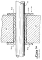
- Fig. 2 illustrates a sectional side view of a preferred embodiment as part of a bearing assembly 200.
- Support housing 202 has a hollow cylindrical bore 206 and a circumferential notch or groove 204 which is undercut into the inside surface of the bore 206 for the purpose of receiving and engaging circumferential rib 106 of the liner 100.
- Shaft 210 extends axially through the interior of bearing liner 100.
- Fig. 3A illustrates a sectional side view of a prior art type bearing liner 301 having radially extending double flanges 304A, 304B - one at each of the two ends of the bearing liner 301.
- Flanges 304A and 304B overlap the edges of the housing bore to retain liner 301 in the housing 302.
- Fig. 3A illustrates how non-axial shaft motion damages the flanges 304A and 304B located at the ends of the prior art bearing liner 301.
- Fig. 3B illustrates a sectional side view of another prior art type bearing liner 311 with a single flange 312 located at one end of said bearing liner 311.
Landscapes
- Engineering & Computer Science (AREA)
- General Engineering & Computer Science (AREA)
- Mechanical Engineering (AREA)
- Sliding-Contact Bearings (AREA)
- Support Of The Bearing (AREA)
- Mounting Of Bearings Or Others (AREA)
Claims (7)
- Zylindrisches Lagerfutter (100), das für ein Einpassen in ein Stützgehäuse (202) vorgesehen ist, wobei das Stützgehäuse (202) eine innere hohlzylindrische Bohrung (206) aufweist, die zylindrische Bohrung (206) eine Umfangsnut (204) im Abstand zu den Enden der Bohrung (206) hat und das zylindrische Lagerfutter (100) besteht aus:
einem hohlen, im wesentlichen zylindrisch geformten Körper (102) mit zwei Enden und einem Spalt (104), der von dem einen zu dem anderen der beiden Enden verläuft,
wobei der zylindrisch geformte Körper (102) weiterhin Stützmittel (106) hat, die zu den beiden Enden des zylindrisch geformten Körpers (102) beabstandet angeordnet sind,
wobei die Stützmittel (106) wenigstens eine Außenrippe (106) aufweisen, die in Umfangsrichtung um den zylindrisch geformten Körper (102) herum verläuft und davon radial vorsteht,
dadurch gekennzeichnet, daß die Rippe (106) zwei gegenüberliegend angeordnete Enden (105A, 105B) hat, von denen jedes Ende (105A, 105B) in der Nähe von und beabstandet jeweils von einer der beiden Kanten (107A, 107B) ist, welche den Spalt (104) in dem zylindrisch geformten Körper (102) definieren. - Lagerfutter nach Anspruch 1, bei welchem der zylindrisch geformte Körper biegsam und elastisch-nachgiebig ist.
- Lagerfutter nach Anspruch 1 oder 2, bei welchem das Lagerfutter als ein einstückiges einziges Stück ausgebildet ist.
- Lagerfutter nach einem der vorhergehenden Ansprüche, bei welchem das Lagerfutter aus einem Material mit geringer Reibung ausgebildet ist.
- Lagerfutter nach Anspruch 4, bei welchem das Material mit geringer Reibung ein polymeres Material ist.
- Lagerfutter nach Anspruch 5, bei welchem das polymere Material ausgewählt ist von NYLON (Warenzeichen), Acetal, Polykarbonat und Polytetrafluorethylen.
- Lagerfutter nach einem der vorhergehenden Ansprüche, bei welchem der Spalt schraubenförmig verläuft.
Applications Claiming Priority (2)
| Application Number | Priority Date | Filing Date | Title |
|---|---|---|---|
| US07/294,208 US4913562A (en) | 1989-01-06 | 1989-01-06 | Thermoplastic bearing liner |
| US294208 | 1989-01-06 |
Publications (2)
| Publication Number | Publication Date |
|---|---|
| EP0377523A1 EP0377523A1 (de) | 1990-07-11 |
| EP0377523B1 true EP0377523B1 (de) | 1994-04-13 |
Family
ID=23132357
Family Applications (1)
| Application Number | Title | Priority Date | Filing Date |
|---|---|---|---|
| EP90300153A Expired - Lifetime EP0377523B1 (de) | 1989-01-06 | 1990-01-05 | Lagerbuchse |
Country Status (4)
| Country | Link |
|---|---|
| US (1) | US4913562A (de) |
| EP (1) | EP0377523B1 (de) |
| CA (1) | CA2006873C (de) |
| DE (1) | DE69007983T2 (de) |
Families Citing this family (29)
| Publication number | Priority date | Publication date | Assignee | Title |
|---|---|---|---|---|
| US5146805A (en) * | 1991-09-12 | 1992-09-15 | General Motors Corporation | Bushing assembly for a pivot connection |
| US5145265A (en) * | 1991-10-18 | 1992-09-08 | Performance Plastics | Double flange pop-in bearing |
| US5409242A (en) * | 1992-01-02 | 1995-04-25 | Gonnocci; Ralph J. | Swivel mountings for a power chuck |
| JP2569074Y2 (ja) * | 1992-02-26 | 1998-04-22 | 自動車機器株式会社 | ラックピニオン式舵取装置のラックブッシュ |
| US5326313A (en) * | 1992-09-21 | 1994-07-05 | Clark United Corporation | Thrust bearing assembly for roof turbine |
| US5352045A (en) * | 1993-01-06 | 1994-10-04 | The Integrated Bearing Co. Ltd. | Means of mounting a revolving cutting element |
| JP2600937Y2 (ja) * | 1993-11-30 | 1999-11-02 | オイレス工業株式会社 | 合成樹脂軸受 |
| US5531524A (en) * | 1994-09-02 | 1996-07-02 | Kohler Co. | Self-adjusting bearing |
| DE19615824A1 (de) * | 1996-04-20 | 1997-10-23 | Igus Gmbh | Gleitlager |
| US5813768A (en) * | 1997-05-16 | 1998-09-29 | Thomson Industries, Inc. | Self-aligning bearing structure |
| WO1999020912A1 (en) | 1997-10-21 | 1999-04-29 | Thomson Industries, Inc. | A plane bearing assembly |
| US6955237B1 (en) | 2003-06-20 | 2005-10-18 | Polaris Industries Inc. | Snowmobile having an adjustable ski stance |
| US7040465B2 (en) * | 2003-09-24 | 2006-05-09 | Bendix Commercial Vehicle Systems Llc | Slack adjuster with wear reduction |
| AT501607B1 (de) * | 2005-03-03 | 2006-10-15 | Sattler Erich | Buchse aus kunststoff |
| DE102006031289A1 (de) * | 2006-05-10 | 2007-11-15 | Heiko Schmidt | Gelenkbuchse |
| US7445296B1 (en) * | 2006-07-24 | 2008-11-04 | Chosen Co., Ltd. | Bicycle hub having enhanced strength |
| US7665747B2 (en) * | 2006-10-13 | 2010-02-23 | Gm Global Technology Operations, Inc. | Steering gear assembly having rack bushing |
| ES2349022T3 (es) * | 2007-11-08 | 2010-12-21 | Saint-Gobain Performance Plastics Pampus Gmbh | Cojinete. |
| DE102009009739A1 (de) * | 2008-04-30 | 2009-11-05 | Continental Teves Ag & Co. Ohg | Kraftfahrzeugbremse mit einer Lagerbuchse bzw. Lagerbuchse für eine Kraftfahrzeugbremse |
| US20110220375A1 (en) * | 2010-03-12 | 2011-09-15 | Connell Jr Richard Joseph | Shaft Alighment And Anti-Corrosion Liner For A Disk Gang |
| US20110262065A1 (en) * | 2010-04-26 | 2011-10-27 | Babu Dharani U | Bearing Assembly With T-Shaped Bearing Member |
| JP5490050B2 (ja) * | 2011-04-14 | 2014-05-14 | トヨタ自動車株式会社 | 軸部材のすべり軸受構造 |
| US10488074B2 (en) | 2011-09-09 | 2019-11-26 | Capital Hardware Supply, Inc. | Airtight bushing for ductwork damper and the like and ductwork damper unit incorporating same |
| DE102012108379A1 (de) * | 2012-09-07 | 2014-03-13 | Johnson Electric Dresden Gmbh | Aktor für eine Ventileinheit zum Regeln eines Fluidflusses |
| US20140199008A1 (en) * | 2013-01-14 | 2014-07-17 | Regal Beloit America, Inc. | Sleeve bearing device |
| DE102014113971A1 (de) * | 2014-09-26 | 2016-03-31 | Thyssenkrupp Ag | Außenbordvorrichtung und Verfahren zum Beschichten einer Außenbordvorrichtung |
| CN104329368A (zh) * | 2014-10-15 | 2015-02-04 | 哈尔滨东安发动机(集团)有限公司 | 一种轴承衬套结构 |
| US10087984B2 (en) | 2015-06-30 | 2018-10-02 | Saint-Gobain Performance Plastics Corporation | Plain bearing |
| US12612941B2 (en) * | 2020-02-19 | 2026-04-28 | Safran Landing Systems Canada Inc. | Field serviceable landing gear bushing |
Family Cites Families (11)
| Publication number | Priority date | Publication date | Assignee | Title |
|---|---|---|---|---|
| NL88909C (de) * | 1953-09-28 | |||
| US2815253A (en) * | 1954-01-15 | 1957-12-03 | Nylacore Corp | Bearing liner |
| US2964341A (en) * | 1957-12-30 | 1960-12-13 | Gen Motors Corp | Pivotal joint |
| US3033623A (en) * | 1958-09-02 | 1962-05-08 | John B Thomson | Fluorocarbon sleeve bearing |
| CH384951A (de) * | 1959-04-07 | 1965-02-26 | Philips Nv | Lager mit einem Kunststoff-Laufflächenteil |
| US3008779A (en) * | 1959-06-03 | 1961-11-14 | John D Spriggs | Nylon lined bearings |
| FR1380200A (fr) * | 1964-01-21 | 1964-11-27 | Emerson Electric Mfg Co | Mécanisme d'entraînement axialement réglable |
| JPS59212521A (ja) * | 1983-05-16 | 1984-12-01 | Miura Kumihimo Kojo:Kk | 滑り軸受 |
| US4603982A (en) * | 1985-02-21 | 1986-08-05 | Auscilla Plastics, Inc. | Molded bearing |
| US4767677A (en) * | 1986-09-17 | 1988-08-30 | Ndc Co., Ltd. | Multi-layer cylindrical bearing |
| US4765757A (en) * | 1987-12-14 | 1988-08-23 | Roller Bearing Company Of America | Self-aligning spherical bushing means |
-
1989
- 1989-01-06 US US07/294,208 patent/US4913562A/en not_active Expired - Lifetime
-
1990
- 1990-01-02 CA CA002006873A patent/CA2006873C/en not_active Expired - Lifetime
- 1990-01-05 EP EP90300153A patent/EP0377523B1/de not_active Expired - Lifetime
- 1990-01-05 DE DE69007983T patent/DE69007983T2/de not_active Expired - Fee Related
Also Published As
| Publication number | Publication date |
|---|---|
| CA2006873A1 (en) | 1990-07-06 |
| EP0377523A1 (de) | 1990-07-11 |
| US4913562A (en) | 1990-04-03 |
| CA2006873C (en) | 1993-03-23 |
| DE69007983D1 (de) | 1994-05-19 |
| DE69007983T2 (de) | 1994-11-10 |
Similar Documents
| Publication | Publication Date | Title |
|---|---|---|
| EP0377523B1 (de) | Lagerbuchse | |
| EP0962676B1 (de) | Lagervorrichtung mit sphärischen Lagerflächen | |
| US4989883A (en) | Static and dynamic shaft seal assembly | |
| US7832100B2 (en) | Seal assembly and method of manufacturing the same | |
| US4274641A (en) | Shaft seal and method | |
| US5419642A (en) | Sealing structure for a bearing | |
| US7017913B2 (en) | Axial shaft seal | |
| CA1177510A (en) | Sealed compound bearing | |
| US5865678A (en) | Two-piece thrust washer for universal joint | |
| GB2033537A (en) | Piston for pneumatic actuator | |
| US6799894B2 (en) | Bushing | |
| GB2095345A (en) | Compound bearing | |
| US5655781A (en) | Unitized radial and facial seal | |
| US6168314B1 (en) | Bearing | |
| JP2007187320A (ja) | ベアリングアッセンブリ | |
| US4410190A (en) | Fluid seal pumping effect lip seal for rotary shaft | |
| CA2170792C (en) | Anti-leakage device | |
| US5813768A (en) | Self-aligning bearing structure | |
| US8720903B2 (en) | Fluid seal assembly | |
| US2859986A (en) | Fluid pressure responsive seal | |
| US20030173745A1 (en) | Seal | |
| KR960001358Y1 (ko) | 합성수지제 스러스트 베어링 | |
| GB2161242A (en) | Seal/bearing member for piston | |
| MXPA99010522A (en) | Self-aligning bearing structure | |
| JPH0461968B2 (de) |
Legal Events
| Date | Code | Title | Description |
|---|---|---|---|
| PUAI | Public reference made under article 153(3) epc to a published international application that has entered the european phase |
Free format text: ORIGINAL CODE: 0009012 |
|
| AK | Designated contracting states |
Kind code of ref document: A1 Designated state(s): DE FR GB IT |
|
| 17P | Request for examination filed |
Effective date: 19901205 |
|
| 17Q | First examination report despatched |
Effective date: 19920609 |
|
| GRAA | (expected) grant |
Free format text: ORIGINAL CODE: 0009210 |
|
| AK | Designated contracting states |
Kind code of ref document: B1 Designated state(s): DE FR GB IT |
|
| REF | Corresponds to: |
Ref document number: 69007983 Country of ref document: DE Date of ref document: 19940519 |
|
| ITF | It: translation for a ep patent filed | ||
| ET | Fr: translation filed | ||
| PLBE | No opposition filed within time limit |
Free format text: ORIGINAL CODE: 0009261 |
|
| STAA | Information on the status of an ep patent application or granted ep patent |
Free format text: STATUS: NO OPPOSITION FILED WITHIN TIME LIMIT |
|
| 26N | No opposition filed | ||
| REG | Reference to a national code |
Ref country code: GB Ref legal event code: IF02 |
|
| PGFP | Annual fee paid to national office [announced via postgrant information from national office to epo] |
Ref country code: GB Payment date: 20070110 Year of fee payment: 18 |
|
| PGFP | Annual fee paid to national office [announced via postgrant information from national office to epo] |
Ref country code: DE Payment date: 20070111 Year of fee payment: 18 |
|
| PGFP | Annual fee paid to national office [announced via postgrant information from national office to epo] |
Ref country code: IT Payment date: 20070618 Year of fee payment: 18 |
|
| PGFP | Annual fee paid to national office [announced via postgrant information from national office to epo] |
Ref country code: FR Payment date: 20070109 Year of fee payment: 18 |
|
| GBPC | Gb: european patent ceased through non-payment of renewal fee |
Effective date: 20080105 |
|
| PG25 | Lapsed in a contracting state [announced via postgrant information from national office to epo] |
Ref country code: DE Free format text: LAPSE BECAUSE OF NON-PAYMENT OF DUE FEES Effective date: 20080801 |
|
| REG | Reference to a national code |
Ref country code: FR Ref legal event code: ST Effective date: 20081029 |
|
| PG25 | Lapsed in a contracting state [announced via postgrant information from national office to epo] |
Ref country code: GB Free format text: LAPSE BECAUSE OF NON-PAYMENT OF DUE FEES Effective date: 20080105 |
|
| PG25 | Lapsed in a contracting state [announced via postgrant information from national office to epo] |
Ref country code: FR Free format text: LAPSE BECAUSE OF NON-PAYMENT OF DUE FEES Effective date: 20080131 |
|
| PG25 | Lapsed in a contracting state [announced via postgrant information from national office to epo] |
Ref country code: IT Free format text: LAPSE BECAUSE OF NON-PAYMENT OF DUE FEES Effective date: 20080105 |