EP0377760A1 - Dispositif d'écartement de pneus de véhicules dans la zone du talon - Google Patents
Dispositif d'écartement de pneus de véhicules dans la zone du talon Download PDFInfo
- Publication number
- EP0377760A1 EP0377760A1 EP89100242A EP89100242A EP0377760A1 EP 0377760 A1 EP0377760 A1 EP 0377760A1 EP 89100242 A EP89100242 A EP 89100242A EP 89100242 A EP89100242 A EP 89100242A EP 0377760 A1 EP0377760 A1 EP 0377760A1
- Authority
- EP
- European Patent Office
- Prior art keywords
- tire
- rollers
- axis
- bead
- spreading
- Prior art date
- Legal status (The legal status is an assumption and is not a legal conclusion. Google has not performed a legal analysis and makes no representation as to the accuracy of the status listed.)
- Granted
Links
- 239000011324 bead Substances 0.000 title claims abstract description 17
- 238000003892 spreading Methods 0.000 claims abstract description 37
- 230000032258 transport Effects 0.000 claims description 4
- 238000012360 testing method Methods 0.000 description 16
- 238000000034 method Methods 0.000 description 6
- 230000001419 dependent effect Effects 0.000 description 1
- 230000002349 favourable effect Effects 0.000 description 1
- 238000010438 heat treatment Methods 0.000 description 1
- 238000007689 inspection Methods 0.000 description 1
- 238000004519 manufacturing process Methods 0.000 description 1
- 238000003825 pressing Methods 0.000 description 1
Images


Classifications
-
- G—PHYSICS
- G01—MEASURING; TESTING
- G01M—TESTING STATIC OR DYNAMIC BALANCE OF MACHINES OR STRUCTURES; TESTING OF STRUCTURES OR APPARATUS, NOT OTHERWISE PROVIDED FOR
- G01M17/00—Testing of vehicles
- G01M17/007—Wheeled or endless-tracked vehicles
- G01M17/02—Tyres
-
- B—PERFORMING OPERATIONS; TRANSPORTING
- B60—VEHICLES IN GENERAL
- B60C—VEHICLE TYRES; TYRE INFLATION; TYRE CHANGING; CONNECTING VALVES TO INFLATABLE ELASTIC BODIES IN GENERAL; DEVICES OR ARRANGEMENTS RELATED TO TYRES
- B60C25/00—Apparatus or tools adapted for mounting, removing or inspecting tyres
- B60C25/14—Apparatus or tools for spreading or locating tyre beads
- B60C25/142—Devices for tightening or expanding the felly, devices for spreading the tyres
Definitions
- the invention relates to a device for spreading vehicle tires in the bead area, in particular for visually inspecting the inner wall of the tires according to the preamble of patent claim 1.
- a known spreading device the tire in the bead area is gripped by two pairs of spreading rollers, spread and pressed against drive rollers.
- the drive rollers set the tire under test in motion during the inspection process.
- the tread of the tire is directed towards the operator.
- Such a spreading device has some disadvantages. Since the working height must be adapted to the angle of the tire flank, it is necessary to lift the tire and insert it into the spreading device. The operator must therefore manually lift many tires (for example, over 1,000 pieces per shift) per day and remove them from the device.
- the tire In order to generate a driving force on the drive unit, in the known device the tire is pressed against the drive rollers by the spreading device. In addition to the various roller resistances, the drive must also overcome the spreading resistance.
- the tire must be rotated by hand on the test fixtures for the second sidekeeping. This process is exhausting and difficult, particularly with heavy tires with large outer diameters.
- the tensioning devices rotate with the tire and thereby cover parts of the tire bead area, which provides a control option for these areas are eliminated.
- the spreading process takes place only at individual points and not over the entire circumference, which affects the uniformity of the test and the test speed.
- the flank is not pressed in from the outside or in all areas, so that the visibility and control options are limited.
- the invention has for its object to provide a device for spreading vehicle tires, which allows largely unobstructed internal control over the entire tire circumference at a relatively high test speed.
- rollers which engage behind the rear bead of a tire with a collar, take over the spreading work.
- the rollers are rotatably mounted on a bearing component, they are stationary with respect to the rotating tire.
- the spreading rollers press the tire against a rotary drive device which rotates the tire by gripping the associated flank.
- the rotary drive device preferably has an annular surface against which the tire surface is pressed.
- a conical shape of the ring surface with an inclination directed away from the rollers is particularly advantageous. The conical surface in particular prevents the tire flank from being pressed inwards when spreading.
- the spreading rollers are preferably conical with a taper towards the free end of the rollers, to which the collar is also attached.
- the bearing component holding the rollers is axially adjustable so that the collar of the spreading rollers can grip the bead and press it outwards.
- the rollers are also preferably adjustable transversely to their axis so that a tire with the rear bead can be placed on the rollers over the bundles.
- the spreading rollers are preferably jointly adjustable with the aid of a second adjusting device.
- a solution in an embodiment of the invention is that a bush is rotatably mounted on the axis of the bearing component, which has a radial portion on which a first Swivel lever is articulated. At the end of the first pivot lever, a second pivot lever is articulated, which in turn is connected at one end in a rotationally fixed manner to a pivot pin.
- a pivot arm is attached to the pivot pin, on each of which an expanding roller is rotatably mounted. If the bearing bush is now rotated, all spreading rollers are pivoted together in order to bring the spreading rollers into or out of engagement with a tire.
- a particularly favorable viewing position is achieved in the device according to the invention if the contact or ring surface is inclined to the horizontal, for example by an angle of approximately 30 ° with respect to the vertical. Such an inclined arrangement also enables a tire to be removed from the spreading device in a simple manner.
- an ejector pin can be adjustably mounted in the ring surface and can be adjusted into a position projecting beyond the ring surface by means of a force device.
- the arrangement is such that the eject pin is on top at the beginning or end of the test process. If a slight de-spreading is carried out after the end of the test process, the ejection pin can push the upper part of the tire with its bead over the collar and bring the tire into an approximately vertical position, so that it can now move freely fall down and can be transported away.
- the ejector pin can be acted upon by a spring, for example, which tries to push it beyond the contact surface.
- an adjustment cylinder can also be used to actuate the ejection pin.
- an embodiment of the invention provides a feed device in which a tire can be centered.
- a gripping device is adjustable between the loading device and the holding device and transports a tire from the loading device to the holding device.
- an inclined feed surface is preferably provided in the receiving device, which has two spaced centering stops, preferably centering rollers. Since the tires are known to have different diameters, an adjustable arrangement of the centering stops is advantageous. Accurate centering would, however, be relatively complex. It may therefore be sufficient if the centering stops are suspended from a spring and the stops are deflected depending on Weight of the tire takes place. Since a tire with a larger diameter normally also has a greater weight, this results in an approximately uniform centering of the tire in the feed device.
- the gripping device preferably has two pairs of rollers which grip the tire in the feed device on diametrically opposite sides on the circumference in order to then move it to the receiving device.
- the gripping rollers must be adjustable towards and away from one another in order to perform a gripping movement. Therefore, according to one embodiment of the invention, the gripping device has two arms, each of which can be pivoted individually and, on the other hand, can be pivoted together about a further axis.
- the gripping device provides a possibility of rotating the gripping rollers in order to rotate the tire by 180 ° from the inside after viewing the first tire flank and to bring it back into the holding device so that the opposite inner flank can also be checked.
- only one pair of rollers can be adjusted with the aid of a suitable rotary drive arranged on one arm of the gripping device, while the other pair of rollers can rotate freely.
- a locking device assigned to the second pair of rollers tion ensures that an assumed position is maintained.
- the tires are known to have different widths. So that the tires now reach a uniform support position on the rear side, the tire is preferably first rotated after being removed from the feed device such that its free side in the receiving device becomes the contact side in the test position. It is understood that the tire is first despread before it can be brought into the second test position by rotating it through 180 °.
- a machine frame 10 holds a spreading device 11, a gripping device 12 and a feed device 14.
- the feed device 14 is located at the upper inclined end of two parallel supports of the frame 10, one of which can be seen at 15 in FIG. 1.
- the supports 15 hold a support section 16 inclined to the horizontal with a support surface 17 which extends approximately in one plane.
- Two rotatably mounted rollers, one of which is shown at 18, are rotatably supported with an axis approximately perpendicular to the support surface 17 above the support surface 17.
- the axes of rotation of the rollers 18 are connected to a spring arrangement 19 and are also displaceable in a slot 20 of the support section 16.
- rollers 18 By pressing the rollers 18, they can therefore be adjusted in the direction of arrow 21 and, for example, the ge Take position shown in dashed lines, the position is dependent on the weight of a tire that is placed on the bearing surface 17, for example by a suitable transport device.
- the spaced-apart rollers 18 provide a first alignment of a given tire, and with the aid of the spring arrangement 19 a further approximate orientation takes place in such a way that, depending on the weight and thus the size of the tire, the latter approximately assumes a centered position on the contact surface 17.
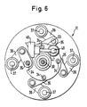
- the spreading device 11 is shown in more detail in FIGS. 4 to 6.
- the spreading device 11 has an axis 30 which is non-rotatably but axially displaceably mounted in a holding device 31 for the spreading device 11 and is adjustable with the aid of an adjusting cylinder (not shown).
- a bushing 32 is rotatably mounted axially by means of ball bearings.
- a disc 33 is rotatably attached on the circumference of the sleeve 32.
- Four bolts 34 are fastened at 90 ° angular intervals in a corresponding perforation in the disk 33.
- a lever 35 is pivotally mounted on each bushing 34 and is articulated on a further lever 36 (see FIG. 6).
- the other end of the lever 36 is non-rotatably seated on a pivot pin 37 which is in a bearing 38 is rotatably mounted.
- the bearing 38 is fixedly connected to the axis 30 by means of a radial plate 39.
- a radial arm 44 is fixedly connected to the axis 30 by means of a bush spanned on the axis 30. In Fig. 4 this arm is shown rotated by 90 °. In reality, it extends backwards perpendicular to the plane of the drawing.
- a link 45 for an adjusting cylinder 46 (Fig. 6) is attached.
- the adjusting rod 47 of the cylinder is connected in an articulated manner to the disk 33 via a transverse bolt 48. When the cylinder 46 is actuated, the disk 33 is therefore rotated about the axis 30 by a certain angle.
- the pivot arms 40 and thus also the rollers 42 are pivoted via the lever connection described, in order to keep the rollers ready for receiving a tire and, after receiving the tire, to spread the tire with the rear bead.
- the axial movement of the axis 30 then leads to the engagement of the collars 43 of the rollers 42 with the bead.
- a ring 50 is attached by means of screws 41 to a cylindrical body 52 which can be set in rotation by means of a rotating device, not shown.
- the ring 50 has a conical ring surface 53, the downward inclination of which extends from the rollers 42. In the described spreading of the tire using the rollers 42, the tire wall is placed against the ring surface 43.
- An ejector pin 56 is slidably mounted in a bearing component 54, which is attached to the rear of the ring 50 with the aid of screws 55.
- the ejector pin 56 is biased by means of a spring, not shown, so that it projects beyond the contact surface 53 in the unloaded state. If a tire is pressed against the contact surface 53, the ejector pin 56 sinks. On the other hand, if the spread is withdrawn, the spring presses the ejector pin 56 outwards and thereby the tire over the respective upper rollers 42 or their bundles, so that the tire is released the inclined position, as indicated in Fig. 1 with 57, almost reaches the vertical and thereby automatically falls. A special removal of the tire from the spreading device 11 is therefore not necessary.
- the gripping device 12 with which a tire is transported from the feeding device 14 to the spreading device 11, is shown in more detail in FIGS. 1 to 3. It has two arms 60, 61 which are articulated at 62, 63 on a shaft 64 between the supports 15.
- the arms 60, 61 are pivoted about an axis perpendicular to the arms 60, 61.
- the shaft 64 can be pivoted about a horizontal axis.
- an arm 65 (FIG. 1) is attached to the shaft, on which the adjusting rod of an adjusting cylinder 66, which is articulated on the holder 31, engages. With the aid of the adjusting cylinder 66, the arms 60, 61 can therefore rotate about a horizontal axis be pivoted.
- An adjusting cylinder 67 is articulated on the shaft 64 and an arm 61.
- a connecting piece 69 is articulated on the articulated connection between the arm 60 and an angled extension 68 of the arm 61 beyond the pivot point 63, the length of which is adjustable.
- Each arm 60, 61 has a head at the free end, of which only one head 70 can be seen in the figures.
- the head 70 supports a pair of rollers 72, 73 which engage the circumference of a tire 57 (Fig. 1). With help of the pairs of rollers on the arms 60, 61, a tire which is centered in the feed device 14 can therefore be centered and moved to the spreading device in order to move it via the spreading rollers 42 against the contact surface 53.
- the pairs of rollers can be rotated in the heads 70 about an axis transverse to the arms 60 or 61.
- a gear 80 sits on the axis of rotation (FIG. 3), which meshes with a larger gear 81, which is rotatably supported by the arm 61 and on which an adjusting cylinder 82 engages, which in turn is articulated on the arm 61 at 83.
- the adjusting cylinder 83 is provided with a roller 84 which rests on a guide plate 85. If the adjusting cylinder 82 is actuated, the assigned pair of rollers is pivoted. A tire received between the pairs of rollers 72 can therefore be rotated. This is necessary in order to get from a first test position, as shown in FIG.
- a tire when it is detected in the feed device 14, is used for spreading during transport Direction 11 first rotated so that the free side in the feeder in the receiving device is the plant side. After the end of the first test run, ie after the tire has been rotated with the aid of the ring 50 and 360 °, the tire is again gripped by the gripping device 12.
- despreading takes place in the manner described, so that the gripping device can rotate the tire by 180 ° with the aid of the pairs of rollers and the described rotary drive device and bring it back into the test position. 3 actuates only one pair of rollers.
- the pair of rollers on the other arm 60 rotates freely.
- the head 70 of the arm 60 is assigned a lock, not shown.
- Such a roller is used to push the tire locally inwards, which gives a special possibility of observation, for example to determine whether there are hairline cracks.
Landscapes
- Physics & Mathematics (AREA)
- General Physics & Mathematics (AREA)
- Engineering & Computer Science (AREA)
- Mechanical Engineering (AREA)
- Testing Of Balance (AREA)
- Tyre Moulding (AREA)
- Processing And Handling Of Plastics And Other Materials For Molding In General (AREA)
- Tires In General (AREA)
Priority Applications (4)
| Application Number | Priority Date | Filing Date | Title |
|---|---|---|---|
| DE8989100242T DE58901042D1 (de) | 1989-01-07 | 1989-01-07 | Vorrichtung zum aufspreizen von fahrzeugreifen im wulstbereich. |
| EP89100242A EP0377760B1 (fr) | 1989-01-07 | 1989-01-07 | Dispositif d'écartement de pneus de véhicules dans la zone du talon |
| AT89100242T ATE74074T1 (de) | 1989-01-07 | 1989-01-07 | Vorrichtung zum aufspreizen von fahrzeugreifen im wulstbereich. |
| US07/337,332 US5013010A (en) | 1989-01-07 | 1989-12-22 | Apparatus for spreading apart vehicle tyres in the bead region |
Applications Claiming Priority (1)
| Application Number | Priority Date | Filing Date | Title |
|---|---|---|---|
| EP89100242A EP0377760B1 (fr) | 1989-01-07 | 1989-01-07 | Dispositif d'écartement de pneus de véhicules dans la zone du talon |
Publications (2)
| Publication Number | Publication Date |
|---|---|
| EP0377760A1 true EP0377760A1 (fr) | 1990-07-18 |
| EP0377760B1 EP0377760B1 (fr) | 1992-03-25 |
Family
ID=8200850
Family Applications (1)
| Application Number | Title | Priority Date | Filing Date |
|---|---|---|---|
| EP89100242A Expired - Lifetime EP0377760B1 (fr) | 1989-01-07 | 1989-01-07 | Dispositif d'écartement de pneus de véhicules dans la zone du talon |
Country Status (4)
| Country | Link |
|---|---|
| US (1) | US5013010A (fr) |
| EP (1) | EP0377760B1 (fr) |
| AT (1) | ATE74074T1 (fr) |
| DE (1) | DE58901042D1 (fr) |
Cited By (2)
| Publication number | Priority date | Publication date | Assignee | Title |
|---|---|---|---|---|
| DE29720708U1 (de) * | 1997-11-21 | 1998-01-08 | Stahlgruber Otto Gruber GmbH & Co, 81675 München | Spreizvorrichtung für Reifen |
| US7699087B2 (en) | 2005-06-29 | 2010-04-20 | Schenck Rotec Gmbh | Method for mounting a pneumatic tire |
Families Citing this family (3)
| Publication number | Priority date | Publication date | Assignee | Title |
|---|---|---|---|---|
| DE102005030692A1 (de) * | 2005-06-29 | 2007-01-11 | Schenck Rotec Gmbh | Verfahren und Vorrichtung zur Montage eines Luftreifens |
| JP6353378B2 (ja) * | 2015-02-02 | 2018-07-04 | リコーエレメックス株式会社 | タイヤ把持装置及びタイヤ検査装置 |
| EP4134227B1 (fr) | 2021-08-12 | 2024-01-31 | JoVision UG (haftungsbeschränkt) | Dispositif d'écartement de pneu, ainsi que système et procédé de traitement de pneu |
Citations (4)
| Publication number | Priority date | Publication date | Assignee | Title |
|---|---|---|---|---|
| US1053641A (en) * | 1907-06-15 | 1913-02-18 | United Shoe Machinery Ab | Heel-breasting machine. |
| US1531973A (en) * | 1923-09-05 | 1925-03-31 | Guy L Pugh | Rim expander and contractor |
| FR1005281A (fr) * | 1947-06-27 | 1952-04-08 | Nanno Th J Collmann | Dispositif de contrôle pour pneus |
| US4751843A (en) * | 1987-04-17 | 1988-06-21 | Scantland Industries, Inc. | Tire inspection apparatus |
Family Cites Families (5)
| Publication number | Priority date | Publication date | Assignee | Title |
|---|---|---|---|---|
| US2895711A (en) * | 1957-05-02 | 1959-07-21 | Charles E Branick | Device for inspecting pneumatic tires |
| US2939678A (en) * | 1958-08-20 | 1960-06-07 | Charles E Branick | Vertically expanding tire spreader |
| US3843888A (en) * | 1972-05-19 | 1974-10-22 | Picker Corp | Method and apparatus for inspecting tires |
| US4293120A (en) * | 1980-03-03 | 1981-10-06 | Robins Robert R | Tire holder and bead expander |
| DE3103342C2 (de) * | 1981-01-31 | 1986-07-03 | Continental Gummi-Werke Ag, 3000 Hannover | Verfahren und Vorrichtung zum Prüfen von Fahrzeugluftreifen |
-
1989
- 1989-01-07 DE DE8989100242T patent/DE58901042D1/de not_active Expired - Fee Related
- 1989-01-07 AT AT89100242T patent/ATE74074T1/de active
- 1989-01-07 EP EP89100242A patent/EP0377760B1/fr not_active Expired - Lifetime
- 1989-12-22 US US07/337,332 patent/US5013010A/en not_active Expired - Fee Related
Patent Citations (4)
| Publication number | Priority date | Publication date | Assignee | Title |
|---|---|---|---|---|
| US1053641A (en) * | 1907-06-15 | 1913-02-18 | United Shoe Machinery Ab | Heel-breasting machine. |
| US1531973A (en) * | 1923-09-05 | 1925-03-31 | Guy L Pugh | Rim expander and contractor |
| FR1005281A (fr) * | 1947-06-27 | 1952-04-08 | Nanno Th J Collmann | Dispositif de contrôle pour pneus |
| US4751843A (en) * | 1987-04-17 | 1988-06-21 | Scantland Industries, Inc. | Tire inspection apparatus |
Cited By (2)
| Publication number | Priority date | Publication date | Assignee | Title |
|---|---|---|---|---|
| DE29720708U1 (de) * | 1997-11-21 | 1998-01-08 | Stahlgruber Otto Gruber GmbH & Co, 81675 München | Spreizvorrichtung für Reifen |
| US7699087B2 (en) | 2005-06-29 | 2010-04-20 | Schenck Rotec Gmbh | Method for mounting a pneumatic tire |
Also Published As
| Publication number | Publication date |
|---|---|
| ATE74074T1 (de) | 1992-04-15 |
| EP0377760B1 (fr) | 1992-03-25 |
| US5013010A (en) | 1991-05-07 |
| DE58901042D1 (de) | 1992-04-30 |
Similar Documents
| Publication | Publication Date | Title |
|---|---|---|
| DE60119252T2 (de) | Vorrichtung und Verfahren zum Prüfen von Artikeln wie Glaswaren | |
| DE68908654T2 (de) | Zuführeinrichtung für Stangenmaterial. | |
| DE4200949C2 (de) | Vorrichtung zur Zerlegung von Kraftfahrzeug-Altreifen | |
| EP3088170B1 (fr) | Mécanisme de positionnement d'un pistolet de pose de clou par rapport à un pneu de véhicule et dispositif et procédé destiné à clouter un pneu de véhicule | |
| DE69108823T2 (de) | Apparat zum Montieren von Speichen eines Speichenrades zwischen die Nabe und Felge. | |
| DE2325240A1 (de) | Pruefvorrichtung fuer luftreifen | |
| EP0611612B1 (fr) | Machine à repousser | |
| EP2442935A1 (fr) | Dispositif de séparation | |
| DE3735858C2 (fr) | ||
| EP1738937B1 (fr) | Procédé et dispositif d'assemblage de pneumatiques | |
| DE69300839T2 (de) | Apparat zum Montieren von Speichen eines Speichenrades zwischen die Nabe und Felge. | |
| DE102007017073A1 (de) | Vorrichtung zur Aufnahme eines im wesentlichen zylindrischen Werkstückes, insbesondere eines Schmuckringes, für die Bearbeitung mit einem Laserstrahl | |
| EP0377760B1 (fr) | Dispositif d'écartement de pneus de véhicules dans la zone du talon | |
| DE102005001212A1 (de) | Verfahren und Vorrichtung zur Montage eines Luftreifens | |
| EP2260975B1 (fr) | Rectifieuse plane et procédé de traitement de pièce usinée par rectification plane | |
| DE69604074T2 (de) | Siebdruckmaschine mit rotierendem siebzylinder | |
| EP1440307B1 (fr) | Dispositif de contrôle radiographique de roues | |
| DE3809146C2 (de) | Vorrichtung zum Zerteilen von Rollen von auf Dornen gewickelter band- oder folienförmiger Ware, insbesonders Papier | |
| WO2000066309A1 (fr) | Affuteuse pour lames de scie presentant une tete de meule porteuse d'au moins un disque de meule et d'au moins une tige de meulage | |
| DE60307441T2 (de) | Verfahren und vorrichtung zur bearbeitung eines werkstücks | |
| DE102021001408A1 (de) | Schleifhalterung | |
| DE4019992C2 (de) | Vorrichtung zur Reifensitzverbesserung von auf Scheibenrädern montierten Luftreifen bei Kraftfahrzeugrädern | |
| EP1564028B1 (fr) | Machine pour mettre en correspondance une roue d'un véhicule | |
| EP3670069A1 (fr) | Support de pièce permettant de supporter un matériau tubulaire dans une machine d'usinage de tubes et machine d'usinage de tubes | |
| CH618370A5 (en) | Appliance for carrying out mechanical operations on pipes |
Legal Events
| Date | Code | Title | Description |
|---|---|---|---|
| PUAI | Public reference made under article 153(3) epc to a published international application that has entered the european phase |
Free format text: ORIGINAL CODE: 0009012 |
|
| 17P | Request for examination filed |
Effective date: 19891116 |
|
| AK | Designated contracting states |
Kind code of ref document: A1 Designated state(s): AT BE CH DE ES FR GB GR IT LI LU NL SE |
|
| 17Q | First examination report despatched |
Effective date: 19910207 |
|
| GRAA | (expected) grant |
Free format text: ORIGINAL CODE: 0009210 |
|
| AK | Designated contracting states |
Kind code of ref document: B1 Designated state(s): AT BE CH DE FR GB IT LI NL SE |
|
| REF | Corresponds to: |
Ref document number: 74074 Country of ref document: AT Date of ref document: 19920415 Kind code of ref document: T |
|
| REF | Corresponds to: |
Ref document number: 58901042 Country of ref document: DE Date of ref document: 19920430 |
|
| GBT | Gb: translation of ep patent filed (gb section 77(6)(a)/1977) | ||
| ITF | It: translation for a ep patent filed | ||
| ET | Fr: translation filed | ||
| PLBE | No opposition filed within time limit |
Free format text: ORIGINAL CODE: 0009261 |
|
| STAA | Information on the status of an ep patent application or granted ep patent |
Free format text: STATUS: NO OPPOSITION FILED WITHIN TIME LIMIT |
|
| 26N | No opposition filed | ||
| PGFP | Annual fee paid to national office [announced via postgrant information from national office to epo] |
Ref country code: SE Payment date: 19931215 Year of fee payment: 6 |
|
| PGFP | Annual fee paid to national office [announced via postgrant information from national office to epo] |
Ref country code: AT Payment date: 19931217 Year of fee payment: 6 |
|
| PGFP | Annual fee paid to national office [announced via postgrant information from national office to epo] |
Ref country code: CH Payment date: 19931220 Year of fee payment: 6 |
|
| PGFP | Annual fee paid to national office [announced via postgrant information from national office to epo] |
Ref country code: FR Payment date: 19931229 Year of fee payment: 6 |
|
| PGFP | Annual fee paid to national office [announced via postgrant information from national office to epo] |
Ref country code: GB Payment date: 19931230 Year of fee payment: 6 |
|
| PGFP | Annual fee paid to national office [announced via postgrant information from national office to epo] |
Ref country code: BE Payment date: 19940104 Year of fee payment: 6 |
|
| PGFP | Annual fee paid to national office [announced via postgrant information from national office to epo] |
Ref country code: NL Payment date: 19940131 Year of fee payment: 6 |
|
| PGFP | Annual fee paid to national office [announced via postgrant information from national office to epo] |
Ref country code: DE Payment date: 19940303 Year of fee payment: 6 |
|
| PG25 | Lapsed in a contracting state [announced via postgrant information from national office to epo] |
Ref country code: GB Effective date: 19950107 Ref country code: AT Effective date: 19950107 |
|
| PG25 | Lapsed in a contracting state [announced via postgrant information from national office to epo] |
Ref country code: SE Effective date: 19950108 |
|
| EAL | Se: european patent in force in sweden |
Ref document number: 89100242.0 |
|
| PG25 | Lapsed in a contracting state [announced via postgrant information from national office to epo] |
Ref country code: LI Effective date: 19950131 Ref country code: CH Effective date: 19950131 Ref country code: BE Effective date: 19950131 |
|
| BERE | Be: lapsed |
Owner name: SPEZIALMASCHINENBAU STEFFEL G.M.B.H. & CO. K.G. Effective date: 19950131 |
|
| PG25 | Lapsed in a contracting state [announced via postgrant information from national office to epo] |
Ref country code: NL Effective date: 19950801 |
|
| GBPC | Gb: european patent ceased through non-payment of renewal fee |
Effective date: 19950107 |
|
| PG25 | Lapsed in a contracting state [announced via postgrant information from national office to epo] |
Ref country code: FR Effective date: 19950929 |
|
| REG | Reference to a national code |
Ref country code: CH Ref legal event code: PL |
|
| NLV4 | Nl: lapsed or anulled due to non-payment of the annual fee |
Effective date: 19950801 |
|
| PG25 | Lapsed in a contracting state [announced via postgrant information from national office to epo] |
Ref country code: DE Effective date: 19951003 |
|
| EUG | Se: european patent has lapsed |
Ref document number: 89100242.0 |
|
| REG | Reference to a national code |
Ref country code: FR Ref legal event code: ST |
|
| PG25 | Lapsed in a contracting state [announced via postgrant information from national office to epo] |
Ref country code: IT Free format text: LAPSE BECAUSE OF NON-PAYMENT OF DUE FEES;WARNING: LAPSES OF ITALIAN PATENTS WITH EFFECTIVE DATE BEFORE 2007 MAY HAVE OCCURRED AT ANY TIME BEFORE 2007. THE CORRECT EFFECTIVE DATE MAY BE DIFFERENT FROM THE ONE RECORDED. Effective date: 20050107 |