EP0377782A2 - Méthode pour la détermination de la teneur en alcool et/ou la valeur calorifique de carburants - Google Patents
Méthode pour la détermination de la teneur en alcool et/ou la valeur calorifique de carburants Download PDFInfo
- Publication number
- EP0377782A2 EP0377782A2 EP89112830A EP89112830A EP0377782A2 EP 0377782 A2 EP0377782 A2 EP 0377782A2 EP 89112830 A EP89112830 A EP 89112830A EP 89112830 A EP89112830 A EP 89112830A EP 0377782 A2 EP0377782 A2 EP 0377782A2
- Authority
- EP
- European Patent Office
- Prior art keywords
- fuel
- circuit
- measuring
- alcohol content
- measurement
- Prior art date
- Legal status (The legal status is an assumption and is not a legal conclusion. Google has not performed a legal analysis and makes no representation as to the accuracy of the status listed.)
- Granted
Links
Images


Classifications
-
- G—PHYSICS
- G01—MEASURING; TESTING
- G01N—INVESTIGATING OR ANALYSING MATERIALS BY DETERMINING THEIR CHEMICAL OR PHYSICAL PROPERTIES
- G01N33/00—Investigating or analysing materials by specific methods not covered by groups G01N1/00 - G01N31/00
- G01N33/26—Oils; Viscous liquids; Paints; Inks
- G01N33/28—Oils, i.e. hydrocarbon liquids
- G01N33/2835—Specific substances contained in the oils or fuels
- G01N33/2852—Alcohol in fuels
Definitions
- the invention relates to a method for determining the alcohol content and / or the calorific value of fuels by measuring electrically measurable quantities in a measuring cell containing the fuel and to a device for carrying out the method.
- the known optical methods are hardly suitable for this purpose, since they mostly interface effects for determining the Use refractive index, from which the alcohol content can then be deduced.
- a disadvantage of this method is also that the mixture to be measured must have a high degree of homogeneity, which in particular must also be present at the interface. The required accuracy was not achieved with this method.
- the invention is therefore based on the object of creating a method of the type described at the outset, which, in particular when used on vehicle engines, permits an accurate and reliable determination of the alcohol content in fuels.
- the measured by arithmetic or circuitry Sizes a measure of the alcohol content and / or the calorific value of the fuel is determined.
- the relative dielectric constant of the fuel mixture fluctuates with the temperature
- particular advantages can be achieved if, in addition to the capacitance measurement, the temperature is also recorded and then the alcohol content and / or the calorific value are determined from these variables.
- At least one processor is imprinted with at least one parameter required for the respective application by setting at least one resistor, the setting of which is read by a processor via an analog / digital converter.
- the dielectric numbers are plotted in the ordinate and the conductance values G in the abscissa.
- Line 11 shows the dependence of the dielectric values on the proportion of methanol admixed with a water content of 0% in the fuel, while line 12 shows the corresponding values represents a share of 2.5% HO.
- the respective measuring points for variable methanol proportions from 0% to 100% (M0 to M100) are plotted on the lines.
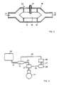
- FIG. 2 shows a preferred embodiment of a measuring cell for carrying out the method according to the invention.
- the fuel enters the measuring cell via inlet 14 and leaves the measuring cell via outlet 15.
- the fuel flow in the planar representation of FIG. 2 is divided into flow paths 16 and 17, which are formed by a central cylinder 18. If the central cylinder 18 and the outer jacket 19 are completely or partially electrically conductive, these walls or wall parts of the measuring cell can represent the electrodes of the frequency-determining capacitor of a measuring or evaluation circuit.
- the at least partially conductive central cylinder 18 as the flow body is the second electrode.
- the central cylinder 18 together with the outer jacket 19 forms the actual measuring capacitor, which encloses the measuring volume.
- the corresponding values can be tapped from terminals 21 and 22, both for the capacitance and for the conductance at the same electrodes. The tapped values are then entered into the corresponding circuit for further processing.
- fuel mixed with alcohol from fuel tank 30 passes via line 31 to measuring cell 13 and from there via line 32 to metering device 33, which is generally an injection pump with corresponding injection nozzles.
- the fuel is supplied in direct or indirect injection to the combustion in engine 34.
- the values of the capacitance and the conductance tapped in the measuring cell 13 are fed via a measuring line 35 to an evaluation circuit or evaluation unit 36.
- the circuit 36 is preferably capable of oscillation and its output frequency can then be evaluated as a measure of the capacitance.
- the amount of fuel in the measuring cell 13 or a part thereof is the dielectric of the capacitive part of the evaluation circuit 36.
- the signals emitted by the evaluation circuit 36 pass via a line 37 to an injection computer 38, which controls the metering device 33 via a line 39.
- the mixture proportion measured in each case in the measuring cell 13 and evaluated in the evaluation unit 36 is therefore not changed operationally, but rather the type of injection is changed depending on the measured and evaluated values.
- the measurement of the alcohol content of the supplied fuel can serve to pre-control the injection quantity, while the fine regulation of the Air ratio takes place via a lambda control of a known type.
- the circuit 36 is integrated in terms of circuitry and programming in the injection system as an evaluation unit. In terms of process engineering, further advantages can be achieved by additionally determining the temperature of the fuel in the measuring cell 13 and entering it in the evaluation unit to compensate for the temperature influence.
- the circuit 36 is a flip-flop circuit in which the amount of fuel in the measuring cell forms the dielectric of the frequency-determining capacitor.
- the flip-flop of the flip-flop is preferably evaluated to determine the capacitance.
- FIG. 4 A preferred embodiment of a flip-flop of the type mentioned is shown in FIG. 4.
- the capacitance 51 of the measuring cell 13 is charged via resistors 52 and 53 from the supply voltage V until a threshold voltage U1, which is formed by resistors 54, 55 and 56 at point 57, is exceeded at comparator 58.
- Comparator output 59 then changes from "high” to “low level” and sets flip-flop 60, whose output 61 thus switches to "high level”.
- a transistor 63 is now switched on via resistor 62, which initiates the discharge process of capacitance 51 via resistor 52. If the voltage across the capacitor 51 now drops below a threshold value U2, which is formed by the resistors 54, 55 and 56 at point 64, a comparator 65 switches its output 66 from “high” to “low level”. This will reset flip-flop 60; transistor 63 switches to the high-resistance state and capacitance 51 is recharged.
- a coupling capacitance for DC suppression can be installed between the resistor 52 and the capacitance 51 with the conductance function 67 of the measuring cell 13, the connection 68 to the comparators 58 and 65 having to be between the resistor 52 and the coupling capacitance.
- the conductance is measured in a second circuit section or in the same circuit.
- the same frequency can be used as for the capacitance measurement, or a different frequency which differs greatly in value, which is generated, for example, in a second oscillator in order to prevent influences of the frequency on the conductance measurement.
- the frequency influence on the conductance measurement can also be used to enable a more precise determination of the alcohol content or the calorific value.
- This measurement of the conductance can take place via a second electrode arrangement or also via the same electrodes that are also used for the capacitance measurement. Since there are advantages in terms of production when using only one electrode arrangement, a larger amount of circuitry is justified in order to carry out the evaluation.
- the measuring electrode can be used in succession to measure capacitance and conductance.
- Another circuit variant is that an LC resonant circuit is used to measure the capacitance.
- This method offers particular advantages because the measured frequency is primarily independent of the conductance between the electrodes. For larger conductivities, e.g. due to additives or contaminants cleaning in the fuel, it is problematic to ensure the function of the circuit.
- the additional measurement of the conductance can be useful, which effects an adaptation of the oscillation circuit to the measured conductance.
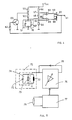
- Measuring cell 74 forms the capacitor 71 of an oscillating circuit 72 which, as another frequency-determining part, has a coil 73.
- Conductance 75 which is parallel to the resonant circuit and acts, among other things, acts as an undesirable element. caused by additives or impurities in the fuel.
- the gain is set as a function of the measured conductance 79 in order to ensure operation of the resonant circuit even with large conductivities.
- the conductance can be measured in a separate circuit 77, as shown in FIG. 5. Either the electrode used for capacitance measurement or a separate electrode arrangement can be used.
- the measurement can also be carried out in the same circuit in which the oscillation is generated, e.g. by determining the amplitude of the vibration, which is a measure of the magnitude of the conductance. Depending on the measured amplitude, the amplitude can be readjusted so that the function of the circuit is ensured at any values of the conductance.
- the inductance can be implemented, for example, with the aid of a gyrator and a capacitor, or particularly advantageously by means of a so-called “switched capacitor” circuit.
- the size of the inductance can even be set electronically and thus e.g. Even when the capacitance of the measuring capacitor changes, the frequency can be regulated to a constant value, which is particularly important for the reproducibility of the measurements.
- resistors 81 and 82 form a voltage divider whose output voltage on line 83 is passed on to a processor 85 for reading in via an analog / digital converter 84.
- Advantages compared to a direct adjustment of the electrical circuit can also be achieved if a complex iterative adjustment process is omitted by taking the set parameters into account, or if an expensive adjustment using a trimming capacitor can be replaced by the resistance adjustment.
- FIG. 7 shows a circuit for measuring the dielectric constant of an unknown medium, the medium forming the dielectric 91 of a capacitor 92, which is the frequency-determining element in an RC resonant circuit 93. Due to production variations, both the capacitance 92, which is dependent on the dielectric number, and the parasitic capacitance 94, which is independent of the dielectric number, fluctuate. In order to be able to carry out a comparison of the output frequency on line 95, which is fed to a further processing circuit 96, over the entire measuring range, one is required Alignment with the aid of two adjustable components, namely a parallel capacitor 97 and a trimming resistor 98, is required.
- the comparison can done only through an iterative process; This means that the measuring capacitance must be filled alternately with media of different dielectric numbers and an adjustment of the capacitor 97 in the presence of a low dielectric constant and resistance trimmer 98 in the presence of a medium with a high dielectric constant must be set until such time as no significant improvement in the Attitude can be achieved.
- the method according to the invention is used.
- the trimming capacitor 97 (FIG. 7) can be omitted and the trimming resistor 98 (FIG. 7) can be converted into a fixed resistor 101.
- the adjustment is now carried out in such a way that firstly a frequency measurement with a medium with a low dielectric constant (e.g. air) and secondly a second measurement with a medium with a particularly high dielectric constant is carried out.
- the result of the frequency measurement is entered into the processor by trimming two resistors 102 and 103, so that it can then compensate for the series spread in future operation by taking into account a corresponding formula.
- the method on which the invention is based can also be used very advantageously in order to adapt each copy of a series to the specific application. For example, by coding with different analog values A selection of output characteristics is made (e.g. voltage proportional to the alcohol content or voltage proportional to the required extension of the injection time).
- an individually programmable module can be saved for programming a serial number, batch number, a product type identification or for the implementation of software protection by setting the parameters again by means of resistance trimming and making them available to the processor via A / D converters.
- hybrid circuits can be integrated particularly advantageously into the housing of sensors, which are compensated for by the type variation and e.g. Adaptation of the output characteristic curve of the sensor by the processor to the specific application to provide an immediately reusable signal.
- the invention is not restricted to the exemplary embodiments shown and described. It can thus be advantageous that, in addition to variables that depend on the material properties of the fuel, independent of the material properties of the fuel, parameters that influence the material properties of the fuel are measured and evaluated.
- the temperature of the fuel can be measured as a variable independent of the material nature of the fuel and can be evaluated to correct the determined alcohol content and / or calorific value.
- the capacitance can be measured not only by an oscillatory circuit in which the fuel contained in the measuring cell is part of a frequency-determining capacitor, but also by the fact that the charging and / or discharging time of a capacitor formed in the measuring cell, the dielectric of which is fuel is used to determine the alcohol content and / or the calorific value.
- a further advantageous possibility is that the measurement of electrically measurable quantities takes place in a circuit which is arranged in the immediate vicinity of the measuring cell, while the further processing of the signals emitted by the measuring circuit takes place in a circuit which is further away.
- All or part of the signals generated by the measuring circuit can also be combined in a combined signal and fed to the further processing circuit via a signal line.
Landscapes
- Chemical & Material Sciences (AREA)
- Health & Medical Sciences (AREA)
- Engineering & Computer Science (AREA)
- Life Sciences & Earth Sciences (AREA)
- Analytical Chemistry (AREA)
- General Physics & Mathematics (AREA)
- General Chemical & Material Sciences (AREA)
- Food Science & Technology (AREA)
- Medicinal Chemistry (AREA)
- Physics & Mathematics (AREA)
- Chemical Kinetics & Catalysis (AREA)
- Biochemistry (AREA)
- General Health & Medical Sciences (AREA)
- Oil, Petroleum & Natural Gas (AREA)
- Immunology (AREA)
- Pathology (AREA)
- Investigating Or Analyzing Materials By The Use Of Electric Means (AREA)
- Output Control And Ontrol Of Special Type Engine (AREA)
- Electrical Control Of Air Or Fuel Supplied To Internal-Combustion Engine (AREA)
- Combined Controls Of Internal Combustion Engines (AREA)
- Investigating Or Analyzing Materials Using Thermal Means (AREA)
- Measurement Of Resistance Or Impedance (AREA)
Applications Claiming Priority (2)
| Application Number | Priority Date | Filing Date | Title |
|---|---|---|---|
| DE3841264A DE3841264C2 (de) | 1988-03-30 | 1988-12-08 | Verfahren zur Feststellung des Alkoholgehaltes und/oder des Heizwertes von Kraftstoffen |
| DE3841264 | 1988-12-08 |
Publications (3)
| Publication Number | Publication Date |
|---|---|
| EP0377782A2 true EP0377782A2 (fr) | 1990-07-18 |
| EP0377782A3 EP0377782A3 (fr) | 1993-01-13 |
| EP0377782B1 EP0377782B1 (fr) | 1995-09-20 |
Family
ID=6368666
Family Applications (1)
| Application Number | Title | Priority Date | Filing Date |
|---|---|---|---|
| EP19890112830 Expired - Lifetime EP0377782B1 (fr) | 1988-12-08 | 1989-07-13 | Méthode pour la détermination de la teneur en alcool et/ou la valeur calorifique de carburants |
Country Status (3)
| Country | Link |
|---|---|
| EP (1) | EP0377782B1 (fr) |
| JP (2) | JP3276629B2 (fr) |
| BR (1) | BR8904033A (fr) |
Cited By (5)
| Publication number | Priority date | Publication date | Assignee | Title |
|---|---|---|---|---|
| EP0411204B1 (fr) * | 1989-07-01 | 1994-11-30 | FEV Motorentechnik GmbH & Co. KG | Méthode de détermination de la teneur en alcool et/ou la valeur calorifique de carburants |
| EP1411349A1 (fr) * | 2002-10-18 | 2004-04-21 | Siemens Building Technologies AG | Sonde d'humidité avec un capteur capacitif d'humidité et méthode de mesure de l'humidité atmosphérique |
| EP1411350A1 (fr) * | 2002-10-18 | 2004-04-21 | Siemens Building Technologies AG | Sonde d'humidité avec un capteur capacitif d'humidité et méthode de mesure de l'humidité atmosphérique |
| WO2011082884A1 (fr) * | 2009-12-17 | 2011-07-14 | Robert Bosch Gmbh | Dispositif de mesure de la composition d'un mélange de carburants |
| WO2024188588A1 (fr) * | 2023-03-14 | 2024-09-19 | Endress+Hauser SE+Co. KG | Dispositif de mesure pour déterminer constante diélectrique et conductivité |
Families Citing this family (7)
| Publication number | Priority date | Publication date | Assignee | Title |
|---|---|---|---|---|
| JP3126872B2 (ja) * | 1994-05-12 | 2001-01-22 | 三菱電機株式会社 | 燃料の混合比率検知装置 |
| DE19710358C2 (de) * | 1997-03-13 | 2000-11-30 | Bosch Gmbh Robert | Mikrostrukturierter Sensor |
| US7466147B2 (en) * | 2005-08-08 | 2008-12-16 | Continental Automotive Systems Us, Inc. | Fluid quality sensor |
| FR2907226B1 (fr) * | 2006-10-13 | 2008-12-12 | Rhodia Recherches & Tech | Dispositif d'analyse fluidique,dispositif de determination de caracteristiques d'un fluide comprenant ce dispositif d'analyse,procedes de mise en oeuvre et procede de criblage correspondants |
| JP5768069B2 (ja) * | 2013-02-12 | 2015-08-26 | 株式会社 堀場アドバンスドテクノ | 比抵抗測定装置、液体試料管理方法及び液体試料管理システム |
| EP2957903A4 (fr) | 2013-02-12 | 2016-10-19 | Horiba Advanced Techno Co Ltd | Circuit de mesure de résistivité, cellule pour mesure d'échantillon liquide, appareil de mesure de résistivité, procédé de réglage d'échantillon liquide et système de réglage d'échantillon liquide |
| US9822713B2 (en) * | 2016-01-26 | 2017-11-21 | Ford Global Technologies, Llc | Network based sharing of automated fuel characteristics |
Family Cites Families (7)
| Publication number | Priority date | Publication date | Assignee | Title |
|---|---|---|---|---|
| DE746944C (de) * | 1941-02-16 | 1944-08-30 | Edgar Woyrsch | Verfahren und Einrichtung zur Bestimmung von Beimengungen |
| DE2544444C3 (de) * | 1975-10-04 | 1981-02-12 | Daimler-Benz Ag, 7000 Stuttgart | Verfahren beim Betrieb einer Brennkraftmaschine |
| US4288741A (en) * | 1979-05-18 | 1981-09-08 | Auburn International, Inc. | Electrical measurement of fluid void fraction for fluid having capacitive and resistive conductive components |
| JPS5698540A (en) * | 1980-01-07 | 1981-08-08 | Hitachi Ltd | Alcohol sensor and method of controlling operation of internal combustion engine using alcohol sensor |
| JPS56104243A (en) * | 1980-01-25 | 1981-08-19 | Hitachi Ltd | Alcohol sensor |
| US4426616A (en) * | 1981-10-06 | 1984-01-17 | Simmonds Precision Products, Inc. | Capacitive measurement system |
| WO1985001352A1 (fr) * | 1983-09-12 | 1985-03-28 | Hydril Company | Appareil de mesure du rapport eau/huile |
-
1989
- 1989-07-13 EP EP19890112830 patent/EP0377782B1/fr not_active Expired - Lifetime
- 1989-07-17 JP JP18274689A patent/JP3276629B2/ja not_active Expired - Lifetime
- 1989-08-01 JP JP19811189A patent/JPH02190755A/ja active Pending
- 1989-08-10 BR BR8904033A patent/BR8904033A/pt not_active IP Right Cessation
Cited By (8)
| Publication number | Priority date | Publication date | Assignee | Title |
|---|---|---|---|---|
| EP0411204B1 (fr) * | 1989-07-01 | 1994-11-30 | FEV Motorentechnik GmbH & Co. KG | Méthode de détermination de la teneur en alcool et/ou la valeur calorifique de carburants |
| EP1411349A1 (fr) * | 2002-10-18 | 2004-04-21 | Siemens Building Technologies AG | Sonde d'humidité avec un capteur capacitif d'humidité et méthode de mesure de l'humidité atmosphérique |
| EP1411350A1 (fr) * | 2002-10-18 | 2004-04-21 | Siemens Building Technologies AG | Sonde d'humidité avec un capteur capacitif d'humidité et méthode de mesure de l'humidité atmosphérique |
| US7030630B2 (en) | 2002-10-18 | 2006-04-18 | Siemens Building Technologies Ag | Moisture sensor with capacitive moisture measuring element and method of determining air humidity |
| US7049829B2 (en) | 2002-10-18 | 2006-05-23 | Siemens Building Technology Ag | Moisture sensor with capacitive moisture measuring element and method of determining air humidity |
| WO2011082884A1 (fr) * | 2009-12-17 | 2011-07-14 | Robert Bosch Gmbh | Dispositif de mesure de la composition d'un mélange de carburants |
| US9097696B2 (en) | 2009-12-17 | 2015-08-04 | Robert Bosch Gmbh | Device for measuring a composition of a fuel mixture |
| WO2024188588A1 (fr) * | 2023-03-14 | 2024-09-19 | Endress+Hauser SE+Co. KG | Dispositif de mesure pour déterminer constante diélectrique et conductivité |
Also Published As
| Publication number | Publication date |
|---|---|
| JP3276629B2 (ja) | 2002-04-22 |
| JPH02190755A (ja) | 1990-07-26 |
| JPH02163431A (ja) | 1990-06-22 |
| EP0377782A3 (fr) | 1993-01-13 |
| EP0377782B1 (fr) | 1995-09-20 |
| BR8904033A (pt) | 1990-10-02 |
Similar Documents
| Publication | Publication Date | Title |
|---|---|---|
| EP0411204B1 (fr) | Méthode de détermination de la teneur en alcool et/ou la valeur calorifique de carburants | |
| EP0335168B1 (fr) | Méthode de fonctionnement d'un moteur à combustion | |
| EP0377782B1 (fr) | Méthode pour la détermination de la teneur en alcool et/ou la valeur calorifique de carburants | |
| DE4035731C2 (de) | Kraftstoffkonzentrations-Überwachungseinheit | |
| DE4311478C2 (de) | Beurteilungssystem für die Art eines Kraftstoffes | |
| DE69204318T2 (de) | Vorrichtung zur Bestimmung der Dielektrizitätskonstante von Kraftstoff. | |
| DE4230313C2 (de) | Vorrichtung zur Erfassung einer dielektrischen Konstanten | |
| DE3714306A1 (de) | Kapazitiver pegelanzeiger | |
| WO1992008991A1 (fr) | Appareil de mesure pour la determination de la teneur en alcool d'un melange | |
| DE19917618B4 (de) | Meßgerät für die Dielektrizitätskonstante einer Flüssigkeit und zugehöriges Verfahren | |
| EP0379644A1 (fr) | Méthode de détermination de la teneur en alcool et/ou la valeur calorifique de carburants | |
| DE4312236A1 (de) | Integrierte Schaltung für einen Mehrkomponentenkraftstoff-Sensor | |
| DE2844761B2 (de) | Schaltungsanordnung zur Überwachung der Zusammensetzung des Abgasgemischs einer mit einem Luft/Brennstoff-Gemisch betriebenen Brennkraftmaschine | |
| DE4237554A1 (fr) | ||
| EP0360790B1 (fr) | Dispositif et procédé pour mesurer la température du carburant dans un moteur à combustion interne réglé électroniquement | |
| EP0464391B1 (fr) | Appareil de mesure et son procédé de mise en oeuvre | |
| EP0377791B1 (fr) | Méthode pour la détermination de la teneur en alcool et/ou la valeur calorifique de carburants | |
| EP0407653B1 (fr) | Méthode de détermination de la teneur en alcool et/ou la valeur calorifique de carburants | |
| DE19623969A1 (de) | Näherungsschalter | |
| EP0653693A2 (fr) | Appareil pour réguler la chute de tension aux bornes d'un utilisateur | |
| EP0407639B1 (fr) | Procédé de mise au point de circuits électroniques | |
| DE4115288C2 (de) | Einrichtung zum Abgleich von Exemplarstreuung und Temperatureinflüssen mindestens eines Sensors | |
| DE3326576A1 (de) | Verfahren und vorrichtung zur erfassung der konzentration von abgasbestandteilen, insbesondere bei brennkraftmaschinen fuer kraftfahrzeuge | |
| DE3433368A1 (de) | Verfahren und einrichtung zur durchfuehrung des verfahrens zur messung des durchsatzes eines stroemenden mediums, insbesondere in verbindung mit brennkraftmaschinen | |
| DE102008003260B4 (de) | Verfahren und Vorrichtung zur Dosierung der Zufuhr einer Harnstofflösung |
Legal Events
| Date | Code | Title | Description |
|---|---|---|---|
| PUAI | Public reference made under article 153(3) epc to a published international application that has entered the european phase |
Free format text: ORIGINAL CODE: 0009012 |
|
| AK | Designated contracting states |
Kind code of ref document: A2 Designated state(s): DE FR GB IT SE |
|
| PUAL | Search report despatched |
Free format text: ORIGINAL CODE: 0009013 |
|
| AK | Designated contracting states |
Kind code of ref document: A3 Designated state(s): DE FR GB IT SE |
|
| 17P | Request for examination filed |
Effective date: 19930809 |
|
| 17Q | First examination report despatched |
Effective date: 19940221 |
|
| GRAA | (expected) grant |
Free format text: ORIGINAL CODE: 0009210 |
|
| AK | Designated contracting states |
Kind code of ref document: B1 Designated state(s): DE FR GB IT SE |
|
| PG25 | Lapsed in a contracting state [announced via postgrant information from national office to epo] |
Ref country code: IT Free format text: LAPSE BECAUSE OF FAILURE TO SUBMIT A TRANSLATION OF THE DESCRIPTION OR TO PAY THE FEE WITHIN THE PRE;WARNING: LAPSES OF ITALIAN PATENTS WITH EFFECTIVE DATE BEFORE 2007 MAY HAVE OCCURRED AT ANY TIME BEFORE 2007. THE CORRECT EFFECTIVE DATE MAY BE DIFFERENT FROM THE ONE RECORDED.SCRIBED TIME-LIMIT Effective date: 19950920 Ref country code: GB Effective date: 19950920 |
|
| REF | Corresponds to: |
Ref document number: 58909448 Country of ref document: DE Date of ref document: 19951026 |
|
| ET | Fr: translation filed | ||
| GBV | Gb: ep patent (uk) treated as always having been void in accordance with gb section 77(7)/1977 [no translation filed] |
Effective date: 19950920 |
|
| PLBE | No opposition filed within time limit |
Free format text: ORIGINAL CODE: 0009261 |
|
| STAA | Information on the status of an ep patent application or granted ep patent |
Free format text: STATUS: NO OPPOSITION FILED WITHIN TIME LIMIT |
|
| 26N | No opposition filed | ||
| PGFP | Annual fee paid to national office [announced via postgrant information from national office to epo] |
Ref country code: DE Payment date: 20080722 Year of fee payment: 20 |
|
| PGFP | Annual fee paid to national office [announced via postgrant information from national office to epo] |
Ref country code: FR Payment date: 20080718 Year of fee payment: 20 |
|
| PGFP | Annual fee paid to national office [announced via postgrant information from national office to epo] |
Ref country code: SE Payment date: 20080724 Year of fee payment: 20 |
|
| EUG | Se: european patent has lapsed |