EP0377806A2 - Verfahren zum Einbau von Futterrohren unter Verwendung eines harzbeschichteten Granulates - Google Patents
Verfahren zum Einbau von Futterrohren unter Verwendung eines harzbeschichteten Granulates Download PDFInfo
- Publication number
- EP0377806A2 EP0377806A2 EP89121031A EP89121031A EP0377806A2 EP 0377806 A2 EP0377806 A2 EP 0377806A2 EP 89121031 A EP89121031 A EP 89121031A EP 89121031 A EP89121031 A EP 89121031A EP 0377806 A2 EP0377806 A2 EP 0377806A2
- Authority
- EP
- European Patent Office
- Prior art keywords
- casing
- slurry
- production
- formation
- zone
- Prior art date
- Legal status (The legal status is an assumption and is not a legal conclusion. Google has not performed a legal analysis and makes no representation as to the accuracy of the status listed.)
- Withdrawn
Links
- 238000000034 method Methods 0.000 title claims abstract description 71
- 239000011347 resin Substances 0.000 title claims abstract description 49
- 229920005989 resin Polymers 0.000 title claims abstract description 49
- 230000015572 biosynthetic process Effects 0.000 claims abstract description 83
- 230000000638 stimulation Effects 0.000 claims abstract description 9
- 230000001976 improved effect Effects 0.000 claims abstract description 4
- 238000004519 manufacturing process Methods 0.000 claims description 79
- 239000002002 slurry Substances 0.000 claims description 71
- 239000004576 sand Substances 0.000 claims description 45
- 239000000463 material Substances 0.000 claims description 24
- 238000012856 packing Methods 0.000 claims description 21
- 238000007596 consolidation process Methods 0.000 claims description 8
- 238000002347 injection Methods 0.000 claims description 8
- 239000007924 injection Substances 0.000 claims description 8
- 230000035515 penetration Effects 0.000 claims description 5
- 230000007704 transition Effects 0.000 claims description 4
- 239000011324 bead Substances 0.000 claims 3
- 239000004743 Polypropylene Substances 0.000 claims 2
- 239000004809 Teflon Substances 0.000 claims 2
- 229920006362 Teflon® Polymers 0.000 claims 2
- -1 polypropylene Polymers 0.000 claims 2
- 229920001155 polypropylene Polymers 0.000 claims 2
- 239000002689 soil Substances 0.000 claims 1
- 238000005755 formation reaction Methods 0.000 abstract description 69
- VYPSYNLAJGMNEJ-UHFFFAOYSA-N Silicium dioxide Chemical compound O=[Si]=O VYPSYNLAJGMNEJ-UHFFFAOYSA-N 0.000 description 44
- 230000006378 damage Effects 0.000 description 13
- 239000004568 cement Substances 0.000 description 7
- 238000005553 drilling Methods 0.000 description 7
- 239000012530 fluid Substances 0.000 description 7
- 230000035699 permeability Effects 0.000 description 7
- 239000011435 rock Substances 0.000 description 7
- 230000008901 benefit Effects 0.000 description 6
- 230000008569 process Effects 0.000 description 6
- 230000003628 erosive effect Effects 0.000 description 4
- 239000011159 matrix material Substances 0.000 description 4
- 230000002028 premature Effects 0.000 description 4
- 239000000126 substance Substances 0.000 description 4
- 238000010420 art technique Methods 0.000 description 3
- 238000004140 cleaning Methods 0.000 description 3
- 238000000605 extraction Methods 0.000 description 3
- 230000033001 locomotion Effects 0.000 description 3
- 230000005012 migration Effects 0.000 description 3
- 238000013508 migration Methods 0.000 description 3
- 239000011148 porous material Substances 0.000 description 3
- 230000004936 stimulating effect Effects 0.000 description 3
- 239000011398 Portland cement Substances 0.000 description 2
- 238000005299 abrasion Methods 0.000 description 2
- 230000001154 acute effect Effects 0.000 description 2
- 150000001875 compounds Chemical class 0.000 description 2
- 238000005520 cutting process Methods 0.000 description 2
- 230000006866 deterioration Effects 0.000 description 2
- 238000006073 displacement reaction Methods 0.000 description 2
- 230000006870 function Effects 0.000 description 2
- 238000011065 in-situ storage Methods 0.000 description 2
- 238000002156 mixing Methods 0.000 description 2
- 230000000149 penetrating effect Effects 0.000 description 2
- 238000005086 pumping Methods 0.000 description 2
- 239000013049 sediment Substances 0.000 description 2
- 239000007787 solid Substances 0.000 description 2
- 238000005406 washing Methods 0.000 description 2
- 239000004215 Carbon black (E152) Substances 0.000 description 1
- 241001002197 Juglans mollis Species 0.000 description 1
- 235000019738 Limestone Nutrition 0.000 description 1
- SNIOPGDIGTZGOP-UHFFFAOYSA-N Nitroglycerin Chemical compound [O-][N+](=O)OCC(O[N+]([O-])=O)CO[N+]([O-])=O SNIOPGDIGTZGOP-UHFFFAOYSA-N 0.000 description 1
- XQCFHQBGMWUEMY-ZPUQHVIOSA-N Nitrovin Chemical compound C=1C=C([N+]([O-])=O)OC=1\C=C\C(=NNC(=N)N)\C=C\C1=CC=C([N+]([O-])=O)O1 XQCFHQBGMWUEMY-ZPUQHVIOSA-N 0.000 description 1
- 239000002253 acid Substances 0.000 description 1
- 230000009471 action Effects 0.000 description 1
- 230000004075 alteration Effects 0.000 description 1
- 238000005422 blasting Methods 0.000 description 1
- 229940000425 combination drug Drugs 0.000 description 1
- 238000005056 compaction Methods 0.000 description 1
- 238000011109 contamination Methods 0.000 description 1
- 238000007796 conventional method Methods 0.000 description 1
- 230000006735 deficit Effects 0.000 description 1
- 230000008021 deposition Effects 0.000 description 1
- 238000013461 design Methods 0.000 description 1
- 230000000694 effects Effects 0.000 description 1
- 230000002708 enhancing effect Effects 0.000 description 1
- 239000003822 epoxy resin Substances 0.000 description 1
- 230000002349 favourable effect Effects 0.000 description 1
- 239000012065 filter cake Substances 0.000 description 1
- 239000000706 filtrate Substances 0.000 description 1
- 239000010419 fine particle Substances 0.000 description 1
- 238000007429 general method Methods 0.000 description 1
- 229960003711 glyceryl trinitrate Drugs 0.000 description 1
- 239000003673 groundwater Substances 0.000 description 1
- 229930195733 hydrocarbon Natural products 0.000 description 1
- 150000002430 hydrocarbons Chemical class 0.000 description 1
- 230000001771 impaired effect Effects 0.000 description 1
- 230000001939 inductive effect Effects 0.000 description 1
- 238000009434 installation Methods 0.000 description 1
- 230000009545 invasion Effects 0.000 description 1
- 238000002955 isolation Methods 0.000 description 1
- 239000006028 limestone Substances 0.000 description 1
- 239000007788 liquid Substances 0.000 description 1
- 238000010297 mechanical methods and process Methods 0.000 description 1
- 230000007246 mechanism Effects 0.000 description 1
- 239000012188 paraffin wax Substances 0.000 description 1
- 239000011236 particulate material Substances 0.000 description 1
- 239000004033 plastic Substances 0.000 description 1
- 239000000088 plastic resin Substances 0.000 description 1
- 230000001681 protective effect Effects 0.000 description 1
- 230000009528 severe injury Effects 0.000 description 1
- 239000000377 silicon dioxide Substances 0.000 description 1
- 239000000243 solution Substances 0.000 description 1
- 239000002904 solvent Substances 0.000 description 1
- 238000010561 standard procedure Methods 0.000 description 1
- 239000011800 void material Substances 0.000 description 1
- XLYOFNOQVPJJNP-UHFFFAOYSA-N water Substances O XLYOFNOQVPJJNP-UHFFFAOYSA-N 0.000 description 1
Images


Classifications
-
- C—CHEMISTRY; METALLURGY
- C09—DYES; PAINTS; POLISHES; NATURAL RESINS; ADHESIVES; COMPOSITIONS NOT OTHERWISE PROVIDED FOR; APPLICATIONS OF MATERIALS NOT OTHERWISE PROVIDED FOR
- C09K—MATERIALS FOR MISCELLANEOUS APPLICATIONS, NOT PROVIDED FOR ELSEWHERE
- C09K8/00—Compositions for drilling of boreholes or wells; Compositions for treating boreholes or wells, e.g. for completion or for remedial operations
- C09K8/60—Compositions for stimulating production by acting on the underground formation
- C09K8/92—Compositions for stimulating production by acting on the underground formation characterised by their form or by the form of their components, e.g. encapsulated material
-
- E—FIXED CONSTRUCTIONS
- E21—EARTH OR ROCK DRILLING; MINING
- E21B—EARTH OR ROCK DRILLING; OBTAINING OIL, GAS, WATER, SOLUBLE OR MELTABLE MATERIALS OR A SLURRY OF MINERALS FROM WELLS
- E21B33/00—Sealing or packing boreholes or wells
- E21B33/10—Sealing or packing boreholes or wells in the borehole
- E21B33/13—Methods or devices for cementing, for plugging holes, crevices or the like
- E21B33/14—Methods or devices for cementing, for plugging holes, crevices or the like for cementing casings into boreholes
-
- E—FIXED CONSTRUCTIONS
- E21—EARTH OR ROCK DRILLING; MINING
- E21B—EARTH OR ROCK DRILLING; OBTAINING OIL, GAS, WATER, SOLUBLE OR MELTABLE MATERIALS OR A SLURRY OF MINERALS FROM WELLS
- E21B43/00—Methods or apparatus for obtaining oil, gas, water, soluble or meltable materials or a slurry of minerals from wells
- E21B43/02—Subsoil filtering
- E21B43/04—Gravelling of wells
-
- E—FIXED CONSTRUCTIONS
- E21—EARTH OR ROCK DRILLING; MINING
- E21B—EARTH OR ROCK DRILLING; OBTAINING OIL, GAS, WATER, SOLUBLE OR MELTABLE MATERIALS OR A SLURRY OF MINERALS FROM WELLS
- E21B43/00—Methods or apparatus for obtaining oil, gas, water, soluble or meltable materials or a slurry of minerals from wells
- E21B43/25—Methods for stimulating production
- E21B43/26—Methods for stimulating production by forming crevices or fractures
Definitions
- the present invention generally relates to improved methods for completing wells formed in both consolidated and unconsolidated formations, and for completing deviated wells formed in consolidated formations which require stimulation by hydraulic fracturing. More particularly, the present invention relates to more efficient and less expensive methods for well completion in underground reservoir rock formations comprising novel techniques for the utilization of permeably consolidatable, resin coated packing materials.
- Sand problems are most common in younger Tertiary sediments, particularly of the Miocene epoch. Notable examples are extensive, troublesome sand production areas in such sediments in the U.S. Gulf Coast, the Los Angeles basin of California, Canadian tar sands, Indonesia, Nigeria, Trinidad and Venezuela. However, sand inflow also occurs in other formations (i.e., older tertiary) if existing in situ stresses are altered by drilling, completion and production operations such that the rock matrix is weakened, thus allowing movement of sand into the wellbore, casing and tubing.
- Sand flow from unconsolidated or failure prone consolidated formations is often controlled through chemical or mechanical means to prevent or correct various problems including premature failure of artificial lift equipment; production loss caused by sand bridging in casing, tubing, and/or flow lines; failure of casing or lines and formations damage near the wellbore due to removal of surrounding formation, compaction, and erosion; abrasion of downhole and surface equipment; and handling and disposal of production formation materials.
- a particulate In the consolidated gravel packing art, a particulate, usually a round silica sand of appropriate size and density, is coated with a suitable oil or water based epoxy or plastic resin and placed in a suitable carrier to form a viscous slurry.
- a resinous particulate slurry is described, for example, in Copeland, et al., U.S. Patent No. 4,074,760.
- This slurry is then injected into the formation through the work string and perforations in the casing to form an area of high mechanical strength and high flow conductivity immediately adjacent the production inlets in the casing.
- a resin coated particulate may be placed between a wire wrapped screen or slotted liner and the casing.
- the wellbore may generally be completed by one of two methods, either cased hole completion or open hole completion.
- the general sequence of performing a cased hole completion includes drilling the hole, setting and cementing casing in place, perforating the casing for production; cleaning the perforation of damage and debris by flowing back, washing the perforations using a perforation wash tool, surging or perforating underbalanced; and stimulating the formation to decrease the skin factor as needed to make the well economically attractive. If the formation requires sand control, this is an additional step which must be performed in addition to the above.
- the typical cased hole completion sequence further contains some or all of the following elements.
- the borehole is drilled with mud as the well fluid leaves a region of impaired or damaged permeability adjacent to the borehole.
- Casing is next run and cemented in place using a Portland cement slurry. Use of such a cement slurry may cause further damage to the formation's native permeability adjacent to the wellbore.
- the Portland cement functions to mechanically support the casing and also to isolate individual permeable formation from each other.
- the drilling mud is exchanged with a clear, solids free, completion fluid to reduce the probability of severe damage to the formation permeability during the critical completion phases where the formation is not protected from incompatible fluid invasion by the protective filter cake of mud solids.
- the casing is next perforated, and a method of cleaning the crushed formation and perforating debris is used to clean and open the perforations.
- the perforation cleaning steps may consist of washing the perforations using a perforation wash tool, backsurging the perforations, or by underbalanced perforating. The latter method is now considered by most operators to be the most effective.
- the appropriate hardware can be positioned in the wellbore for either a RCS consolidation, a gravel pack, or a conventional completion without any sand control.
- the general sequence of performing an open hole completion includes drilling a pilot hole through all formation down to the top of the deepest target formation; setting and cementing casing in place; drilling a pilot hole through the deepest target formation; opening the hole size of the formations to be completed using an underreamer to remove damage from prior operations; and stimulating the formation to decrease the skin factor, if needed, to make the well economical. Again, sand control measures are performed in addition to these steps.
- the typical open hole completion further comprises the following elements.
- the final borehole through the interval to be completed is preferably drilled with a nondamaging drilling mud. Casing is then set above the productive interval. If the interval to be completed has not already been drilled though, a pilot hole is drilled through the interval or intervals to be completed. If the pilot hole is drilled with a damaging drill mud, then the hole must be underreamed through the completion internal to remove as much as possible of the damaged formation adjacent to the wellbore. This operation is normally performed with a underreamer rotated on a workstring of pipe, and using a non-damaging circulating fluid to carry cuttings to surface.
- the desired sections of formation may be isolated from each other using inflatable cement packers, or, alternatively, the isolated sections of hole may be cemented using formation packers and port collars.
- a gravel slurry is placed between a slotted liner or wire wrapped screen and the exposed formation, again using ported collars and a combination tool.
- the combination tool functions to open and close the port collar and also isolates the port collar to direct the slurry placement.
- the production rate possible from the above described completions techniques may be enhanced by stimulating the well.
- Well stimulation may consist of a chemical stimulation using some kind of acid or solvent solution to dissolve or remove material from the formation.
- the well may be stimulated by hydraulic fracturing. In hydraulic fracturing, a fracture is created in the reservoir rock by hydraulic forces and then propped open by a particulate material. This propped fracture provides a low resistance flow channel from deep within the formation to the wellbore.
- Underreaming is generally the preferred mechanical method for damage removal prior to placement of sand control measures in open hole completions. Underreaming, however, is highly time consumptive since it entails the introduction of the underreaming tool via a work string, hence necessitating at least one "round trip" for each production interval. Furthermore, additional trips may be required if hole stability problems are encountered. Even when the production intervals are grouped in a single zone, such damage removal processes can involve extensive time expenditures. Such time expenditures are especially noteworthy in deeper wells or in deviated wells having a large net length. Additionally, underreaming procedures conducted in some unconsolidated formations might result in a complete collapse of the borehole, and hence abandonment of the well.
- the present invention addresses the aforementioned and other disadvantages by providing improved methods for completing wells in unconsolidated sand and limestone formations.
- the present invention also provides for the completion of deviated wells in consolidated formations which require stimulation by hydraulic fracturing.
- an open hole resin coated particulate pack is placed around the uncemented production casing across the projected production interval(s).
- the well is next hydraulically fractured with a resin coated sand proppant utilizing the limited entry perforating technique through the open hole resin coated sand consolidation.
- a conductive channel or series of channels into the reservoir is realized with minimized restriction close to the wellbore region.
- the casing is then perforated using a large hole diameter, shallow penetration depth, high shot density perforating gun.
- a gravel pack is performed inside the casing using a wire wrapped screen and a gravel packer.
- the wellbore Before production casing may be set in the wellbore, the wellbore must first be mechanically underreamed in order to remove the mudcake and also to enhance the diameter of the void around the casing. In such a fashion, the resin coated sand or particulate slurry is able to contact uncontaminated areas of the formation while establishing a larger cross sectional area of permeable consolidation.
- the wellbore is underreamed or scoured via an abrasive sand slurry which is injected down the casing or inner string and into turbulent contact with the formation. The turbulent action of the abrasive slurry simultaneously removes the mudcake from the walls of the wellbore while contouring the wellbore to a desired production diameter.
- This abrasive slurry may then be displaced in the wellbore by the introduction of a resin coated particulate slurry as above described which is introduced at a pressure so as to result in optimal flow characteristics, e.g. either transition flow or turbulent flow rates which do not impart sufficient stress on the walls of the borehole to cause formation sloughing or undesirable mixing of formation material with the RCP slurry.
- This second slurry then is allowed to set around the production casing or cement packer to form a consolidated zone of high conductivity.
- the present invention has a number of advantages over the prior art.
- the proposed method of completion results in a high conductivity region surrounding the wellbore which acts like a channel between the fracture flow and the high density perforations while giving fracture propagation control during the hydraulic fracturing operation. As such, production efficiency is dramatically increased.
- a second advantage of the present method is the ability to secure production casing along a potential pay zone without cementing, therefore avoiding undue contamination and formation damage along the production zone so as to necessitate time consuming opening, underreaming operations, or other rigorous methods of debris removal which risk formation damage.
- Another advantage of the present invention is the ability to form an annulus of desired diameter without the need to resort to mechanical underreamers or openers. Such ability greatly reduces or eliminates the need to trip mechanical underreamers or the like in the hole. This advantage is particularly significant in deep wells, wells formed in highly unconsolidated formation, or in deviated wells which involve an abnormally long net production lengths.
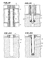
- Figure 1 generally illustrates a side, cross sectional view of a well completed in an unconsolidated formation in accordance with prior art techniques of well completion utilizing either a consolidatable resin coated packing material or a gravel pack.
- a production zone 10 such as a younger tertiary sand lens, extending between two nonproducing intervals 14.
- the wellbore has been "opened” or “underreamed” with a tool 20 similar to that illustrated in Figure 1B.
- Hole opening devices 20 such as that illustrated in Figure 1B, feature cutting arms which may be expanded by hydraulic pressure after the tool 20 is first run through casing in order to enlarge the open hole beneath the shoe 19.
- Hole openers or underreamers 20 are used to enlarge the hole to allow for increased gravel thickness around slotted or screen type liners. The result of which is shown in Figure 1C.
- Such underreaming operations are also necessary to remove the mudcake from the wall of the wellbore and form the adjacent damaged region.
- a gravel pack normally consisting of a particulate slurry (RCP) or a resin coated particulate slurry, is injected in the widened annular space 15 formed by the underreamer 20 between the walls of the wellbore 17 and the casing 2.
- RCP particulate slurry
- this viscous slurry is injected into the annular space by pumping from the workstring through a crossover tool into the annular space between the slotted or screen liner, until the annulus is filled with the particulate, whereupon the well is essentially complete except for installation of tubing and wellhead.
- Puddle Pack Another open hole type completion utilizing a resin coated particulate slurry is the patented process known as the Puddle Pack.
- This type of completion is performed on a well having an open hole interval such as that created by shooting the well with nitroglycerine.
- the Puddle Pack process entails filling the open hole space with a RCP slurry.
- a perforating tool (not shown) is then introduced in the well, forming perforations 16 through the casing 2 and cement 4 into the high conductivity region 12 formed by the resin coated Puddle Pack, whereupon the well may then be produced.
- the method of the present invention generally facilitates the above-mentioned prior art technique while enhancing the productivity of a given formation.
- the method of the present invention further results in the realization of substantial economic benefits in deeper wells, as well as in deviated wells.
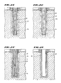
- Figure 2 illustrates a bore 46 formed in a producing formation 40 situated vertically adjacent a nonproducing horizon 44 such as a shale or nonpermeable sand.
- intermediate casing 42 has been set above the zone of interest 40 to the extent of this nonproducing zone 44.
- the bore 46 is then recontoured or underreamed ( Figure 2B) to remove the mudcake formed along the walls of the wellbore and to establish an annulus 48 of sufficient size to sustain the gravel pack.
- This recontouring or opening may be accomplished via an underreaming tool as illustrated in Figure 18.
- this underreaming may be accomplished via the introduction of an abrasive sand slurry as will be further discussed herein.
- production casing 50 is then set in the enlarged bore 46. Once the casing is in place, an inner workstring 56 is preferably set in place. (See Fig. 2C & 2D).
- the well is now prepared to receive the resin coated particulate slurry (RCP).
- RCP resin coated particulate slurry
- a slotted liner or wire wrapper screen (not shown) may be used and a gravel pack performed between the screen and the casing later in the completion sequence.
- the placement of the resin coated packing material is accomplished by pumping the resin coated slurry 60 down through the workstring 56.
- the workstring 56 is preferably sealed into a casing shoe 54 or a float shoe if the zone to receive the packing material exists at the point of the casing seat. Otherwise, the workstring 56 is sealed to or isolated with a port or multistage cementing tool (not shown) placed at an appropriate depth in the casing string.
- the resin coated slurry is then pumped down the workstring 56 through the casing shoe 54 or port in the casing string (not shown) and up across the zone of interest 10.
- the resultant high conductivity region 60 is equally consolidated around the production casing 50 so as to ensure even production flow.
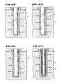
- the casing is then perforated ( Figure 2G). Such perforation may be accomplished via a deep penetrating bullet perforation or jet charge type technique. Once perforated at the desired interval spacing, the formation is then fractured. In a preferred embodiment, formation fracturing is induced by injecting a suitable proppant, such as additional amounts of the resin coated slurry, into the perforations 62 (See 2H).
- a suitable proppant such as additional amounts of the resin coated slurry
- the formation is then re-perforated ( Figure 2I).
- a large bore, high shot density, shallow penetration, tubing conveyed perforation device is utilized to achieve this reperforation. Since a highly permeable sheath of resin coated particulates surrounds the casing, the optimal charge design is a maximum bore charge which will penetrate only the casing. Where extensive migration of formation sands through the gravel pack is expected, a slotted or perforated screen 80 may then be introduced inside the production casing.
- the consolidatable, resin coated packing material e.g. Hydrocon-E
- Hydrocon-E is important to provide a high permeability interface region or "gravel pack" to connect the wellbore to the fracture.
- "gravel pack” generally provides the following advantages:
- a ported section of casing covered by a wire wrapped screen is introduced above the zone of interest so as to facilitate circulation of slurry across a given production interval, and to give more complete coverage and packing of the resin coated sand.
- An upper ported section or multistage cementing tool may be added in combination with formation packers so as to allow the completion of multiple zones utilizing the proposed method.
- the use of multistage cementing tools and formation packers such as a Lynes ECP open hole gravel pack system, allows isolation of multiple high consolidation zones by placement of cemented sections between the production zones.
- the resin coated sand or particulate slurry is preferably introduced through the workstring or casing at a rate and pressure so as to result in sub-erosive flow of the slurry into the annulus around the casing.
- Sub-erosive flow, or a flow rate greater than laminar flow but less than the flow rate sufficient to cause shear and erosion of the borehole well to precipitate formation sloughing or mixing of formation material with the consolidatible slurry enhances the consolidation of the resin coated packing material by filling in voids created during premature "setting" of the sand pack, or as created by off center placement of the casing in the wellbore.
- FIGS 5A-D generally exemplify how a casing symmetrically aligned and seated in the wellbore 210 may begin to experience lateral displacement along its length to a point where it contacts or is near contact with the wall 212 of the wellbore.
- a casing 200 is initially centered in the wellbore at the shoe (not shown), but at only 48" above the shoe the casing already demonstrates substantial off-center deflection from the wellbore axis. This deflection increases at 72" (5C) and at 120" (5D) above the shoe.
- the wellbore Prior to setting production casing through the production zone, the wellbore must often be "underreamed” or “opened” to remove mudcake from the walls of the wellbore. When sand control is implemented, the wellbore will also often have to be underreamed to an additional diameter so as to support the packing material.
- Underreaming or opening procedures while vital to efficient production from the zone, involves the use of mechanical tools which must be run or “tripped” into the hole. Such tripping necessitates the utilization of a derrick rig and involves a time consumptive and hence expensive process. Such is particularly true if a plurality of individual producing horizons must be addressed, each involving an individual underreaming operation.
- One embodiment of the present invention substantially eliminates the need for this time-consuming procedure.
- casing is run across the target zone in the original borehole and hole opening, and damage removal is accomplished immediately prior to setting the casing via placement of the RCP.
- Figures 3A-C illustrate yet another preferred embodiment of the invention which addresses the above noted disadvantages of well completion.
- Figures 3A-C generally illustrate a bore 82 formed through a nonproducing zone 44 into an adjacent producing horizon 40.
- intermediate casing 42 has been set in the nonproductive zone 44 and cemented in place.
- From this intermediate casing 42 has been hung production casing or liner 80.
- This casing 80 is run into the bore 82 which has not been underreamed or opened.
- an abrasive slurry 90 is pumped down into the casing at a pressure so as to induce turbulent flow of the abrasive slurry 90 down the bottom of the casing 80 and up between said casing 80 and the wellbore 82.
- This abrasive slurry 90 strips the mudcake from the wellbore wall while simultaneously recontouring the wellbore 82 to a diameter sufficient to accept the resin coated packing material as will be later described.
- a resin coated packing (RCP) material 100 is then injected down into the casing 80 into the resulting annulus 94.
- This packing material 100 displaces the abrasive slurry 90 which is then retrieved along with formation debris at the surface.
- the resin coated packing material is injected at a pressure so as to induce sub-erosive flow in the slurry 100. As such, a maximum flow rate is achieved in this material so as to give sufficient displacement of debris by the RCP slurry 100 while not inducing additional abrasion of the wellbore wall 83.
- a separate abrasive slurry e.g. walnut hulls or blasting sand, and a packing material
- a single slurry compound e.g., a resin coated sand
Landscapes
- Life Sciences & Earth Sciences (AREA)
- Engineering & Computer Science (AREA)
- Geology (AREA)
- Mining & Mineral Resources (AREA)
- General Life Sciences & Earth Sciences (AREA)
- Environmental & Geological Engineering (AREA)
- Fluid Mechanics (AREA)
- Physics & Mathematics (AREA)
- Geochemistry & Mineralogy (AREA)
- Chemical & Material Sciences (AREA)
- Materials Engineering (AREA)
- Organic Chemistry (AREA)
- Piles And Underground Anchors (AREA)
- Consolidation Of Soil By Introduction Of Solidifying Substances Into Soil (AREA)
- Physical Or Chemical Processes And Apparatus (AREA)
Applications Claiming Priority (2)
| Application Number | Priority Date | Filing Date | Title |
|---|---|---|---|
| US07/295,263 US4917188A (en) | 1989-01-09 | 1989-01-09 | Method for setting well casing using a resin coated particulate |
| US295263 | 1989-01-09 |
Publications (2)
| Publication Number | Publication Date |
|---|---|
| EP0377806A2 true EP0377806A2 (de) | 1990-07-18 |
| EP0377806A3 EP0377806A3 (de) | 1991-04-10 |
Family
ID=23136951
Family Applications (1)
| Application Number | Title | Priority Date | Filing Date |
|---|---|---|---|
| EP19890121031 Withdrawn EP0377806A3 (de) | 1989-01-09 | 1989-11-13 | Verfahren zum Einbau von Futterrohren unter Verwendung eines harzbeschichteten Granulates |
Country Status (4)
| Country | Link |
|---|---|
| US (1) | US4917188A (de) |
| EP (1) | EP0377806A3 (de) |
| CA (1) | CA2002037A1 (de) |
| NO (1) | NO894327L (de) |
Cited By (1)
| Publication number | Priority date | Publication date | Assignee | Title |
|---|---|---|---|---|
| EP0426427A3 (en) * | 1989-10-30 | 1991-11-06 | Halliburton Company | Well completion method |
Families Citing this family (27)
| Publication number | Priority date | Publication date | Assignee | Title |
|---|---|---|---|---|
| US5095987A (en) * | 1991-01-31 | 1992-03-17 | Halliburton Company | Method of forming and using high density particulate slurries for well completion |
| US5163512A (en) * | 1991-08-28 | 1992-11-17 | Shell Oil Company | Multi-zone open hole completion |
| US5211234A (en) * | 1992-01-30 | 1993-05-18 | Halliburton Company | Horizontal well completion methods |
| US5279370A (en) * | 1992-08-21 | 1994-01-18 | Halliburton Company | Mechanical cementing packer collar |
| US5332037A (en) * | 1992-11-16 | 1994-07-26 | Atlantic Richfield Company | Squeeze cementing method for wells |
| US5375661A (en) * | 1993-10-13 | 1994-12-27 | Halliburton Company | Well completion method |
| US5875843A (en) * | 1995-07-14 | 1999-03-02 | Hill; Gilman A. | Method for vertically extending a well |
| US5960880A (en) * | 1996-08-27 | 1999-10-05 | Halliburton Energy Services, Inc. | Unconsolidated formation stimulation with sand filtration |
| CA2226928C (en) * | 1997-01-14 | 2006-11-28 | Gillman A. Hill | Multiple zone well completion method and apparatus |
| US5791415A (en) * | 1997-03-13 | 1998-08-11 | Halliburton Energy Services, Inc. | Stimulating wells in unconsolidated formations |
| US6367566B1 (en) * | 1998-02-20 | 2002-04-09 | Gilman A. Hill | Down hole, hydrodynamic well control, blowout prevention |
| US6216786B1 (en) * | 1998-06-08 | 2001-04-17 | Atlantic Richfield Company | Method for forming a fracture in a viscous oil, subterranean formation |
| RU2160360C2 (ru) * | 1998-07-28 | 2000-12-10 | Мобил Ойл Корпорэйшн | Скважинный фильтр |
| US6155348A (en) * | 1999-05-25 | 2000-12-05 | Halliburton Energy Services, Inc. | Stimulating unconsolidated producing zones in wells |
| US6253851B1 (en) * | 1999-09-20 | 2001-07-03 | Marathon Oil Company | Method of completing a well |
| US6257335B1 (en) | 2000-03-02 | 2001-07-10 | Halliburton Energy Services, Inc. | Stimulating fluid production from unconsolidated formations |
| US6810960B2 (en) | 2002-04-22 | 2004-11-02 | Weatherford/Lamb, Inc. | Methods for increasing production from a wellbore |
| CA2492422C (en) | 2004-01-13 | 2008-11-04 | Weatherford/Lamb, Inc. | A system for evaluating over and underbalanced drilling operations |
| US7458423B2 (en) * | 2006-03-29 | 2008-12-02 | Schlumberger Technology Corporation | Method of sealing an annulus surrounding a slotted liner |
| US20080289812A1 (en) * | 2007-04-10 | 2008-11-27 | Schlumberger Technology Corporation | System for downhole packing |
| BRPI0911801A2 (pt) * | 2008-05-22 | 2015-10-06 | Exxonmobil Upstream Res Co | método para regular escoamento em um poço de hidrocarbonetos. |
| US20130008654A1 (en) * | 2011-07-05 | 2013-01-10 | Halliburton Energy Services, Inc. | Method for Drilling and Completion Operations with Settable Resin Compositions |
| US11959371B2 (en) * | 2012-11-16 | 2024-04-16 | Us Well Services, Llc | Suction and discharge lines for a dual hydraulic fracturing unit |
| US9896269B2 (en) | 2015-05-01 | 2018-02-20 | Halliburton Energy Services, Inc. | Method of forming a subterranean gas storage vessel |
| US20240368961A1 (en) * | 2023-05-01 | 2024-11-07 | Saudi Arabian Oil Company | Protecting the casing-casing annulus in hydrocarbon producing wellbores |
| US12448559B1 (en) | 2024-06-06 | 2025-10-21 | Halliburton Energy Services, Inc. | Puddle job with delayed setting of resin via a polymerization reaction with an activator |
| US12448873B1 (en) * | 2024-06-06 | 2025-10-21 | Halliburton Energy Services, Inc. | Puddle job with delayed setting of resin |
Family Cites Families (20)
| Publication number | Priority date | Publication date | Assignee | Title |
|---|---|---|---|---|
| US2986538A (en) * | 1958-10-13 | 1961-05-30 | Lyle E Nesbitt | Particulate resin-coated composition |
| US3393736A (en) * | 1966-08-17 | 1968-07-23 | Gulf Research Development Co | Well completion method |
| US3670817A (en) * | 1970-11-05 | 1972-06-20 | Shell Oil Co | Method of gravel-packing a production well borehole |
| US3780807A (en) * | 1972-09-13 | 1973-12-25 | Exxon Production Research Co | Gravel-packing method and composition |
| US3976135A (en) * | 1972-10-02 | 1976-08-24 | Halliburton Company | Method of forming a highly permeable solid mass in a subterranean formation |
| US4042032A (en) * | 1973-06-07 | 1977-08-16 | Halliburton Company | Methods of consolidating incompetent subterranean formations using aqueous treating solutions |
| US3800847A (en) * | 1973-07-20 | 1974-04-02 | J Rike | Sand consolidation by adhesive agent and particulate pack |
| US3929191A (en) * | 1974-08-15 | 1975-12-30 | Exxon Production Research Co | Method for treating subterranean formations |
| US4074760A (en) * | 1976-11-01 | 1978-02-21 | The Dow Chemical Company | Method for forming a consolidated gravel pack |
| US4081030A (en) * | 1976-11-01 | 1978-03-28 | The Dow Chemical Company | Aqueous based slurry with chelating agent and method of forming a consolidated gravel pack |
| US4199484A (en) * | 1977-10-06 | 1980-04-22 | Halliburton Company | Gelled water epoxy sand consolidation system |
| US4220566A (en) * | 1978-03-21 | 1980-09-02 | The Dow Chemical Company | Aqueous based slurry containing enediol breaker and method for forming a consolidated gravel pack |
| US4247430A (en) * | 1979-04-11 | 1981-01-27 | The Dow Chemical Company | Aqueous based slurry and method of forming a consolidated gravel pack |
| US4378845A (en) * | 1980-12-30 | 1983-04-05 | Mobil Oil Corporation | Sand control method employing special hydraulic fracturing technique |
| US4428427A (en) * | 1981-12-03 | 1984-01-31 | Getty Oil Company | Consolidatable gravel pack method |
| US4589490A (en) * | 1984-11-08 | 1986-05-20 | Conoco Inc. | Well bore recompletion |
| US4685519A (en) * | 1985-05-02 | 1987-08-11 | Mobil Oil Corporation | Hydraulic fracturing and gravel packing method employing special sand control technique |
| US4665988A (en) * | 1986-04-04 | 1987-05-19 | Halliburton Company | Method of preparation of variable permeability fill material for use in subterranean formations |
| US4796701A (en) * | 1987-07-30 | 1989-01-10 | Dowell Schlumberger Incorporated | Pyrolytic carbon coating of media improves gravel packing and fracturing capabilities |
| US4800960A (en) * | 1987-12-18 | 1989-01-31 | Texaco Inc. | Consolidatable gravel pack method |
-
1989
- 1989-01-09 US US07/295,263 patent/US4917188A/en not_active Expired - Lifetime
- 1989-10-30 NO NO89894327A patent/NO894327L/no unknown
- 1989-11-01 CA CA002002037A patent/CA2002037A1/en not_active Abandoned
- 1989-11-13 EP EP19890121031 patent/EP0377806A3/de not_active Withdrawn
Cited By (1)
| Publication number | Priority date | Publication date | Assignee | Title |
|---|---|---|---|---|
| EP0426427A3 (en) * | 1989-10-30 | 1991-11-06 | Halliburton Company | Well completion method |
Also Published As
| Publication number | Publication date |
|---|---|
| NO894327L (no) | 1990-07-10 |
| EP0377806A3 (de) | 1991-04-10 |
| US4917188A (en) | 1990-04-17 |
| CA2002037A1 (en) | 1990-07-09 |
| NO894327D0 (no) | 1989-10-30 |
Similar Documents
| Publication | Publication Date | Title |
|---|---|---|
| US5058676A (en) | Method for setting well casing using a resin coated particulate | |
| US4917188A (en) | Method for setting well casing using a resin coated particulate | |
| US4685519A (en) | Hydraulic fracturing and gravel packing method employing special sand control technique | |
| AU2005224422B2 (en) | Methods of isolating hydrajet stimulated zones | |
| US4549608A (en) | Hydraulic fracturing method employing special sand control technique | |
| US5505260A (en) | Method and apparatus for wellbore sand control | |
| AU2003203538B8 (en) | Methods and apparatus for improving performance of gravel packing systems | |
| US6776238B2 (en) | Single trip method for selectively fracture packing multiple formations traversed by a wellbore | |
| US6766862B2 (en) | Expandable sand control device and specialized completion system and method | |
| US6719051B2 (en) | Sand control screen assembly and treatment method using the same | |
| RU2359115C2 (ru) | Управление по нескольким азимутам вертикальными трещинами, возникающими при гидравлических разрывах в рыхлых или слабосцементированных осадочных породах | |
| US5947200A (en) | Method for fracturing different zones from a single wellbore | |
| US7152689B2 (en) | System and method to seal by bringing the wall of a wellbore into sealing contact with a tubing | |
| US5329998A (en) | One trip TCP/GP system with fluid containment means | |
| US20030075326A1 (en) | Well completion method | |
| AU8916191A (en) | Method for controlling solids accompanying hydrocarbon production | |
| EP0857248B1 (de) | Komplettierungsvorrichtung für bohrlöcher | |
| US4589490A (en) | Well bore recompletion | |
| US4825944A (en) | Gravel pack completion for in situ leach wells | |
| EP0823538A2 (de) | Verfahren zur Stimulierung einer unterirdischen Bohrung | |
| Rodvelt | Vertical well construction and hydraulic fracturing for CBM completions | |
| US12378862B1 (en) | Particulate buffer for attenuating corrosion of dissolvable frac plug | |
| JPT staff | Specialists Share Knowledge of Sand-Control Methods |
Legal Events
| Date | Code | Title | Description |
|---|---|---|---|
| PUAI | Public reference made under article 153(3) epc to a published international application that has entered the european phase |
Free format text: ORIGINAL CODE: 0009012 |
|
| AK | Designated contracting states |
Kind code of ref document: A2 Designated state(s): AT BE CH DE ES FR GB GR IT LI LU NL SE |
|
| PUAL | Search report despatched |
Free format text: ORIGINAL CODE: 0009013 |
|
| AK | Designated contracting states |
Kind code of ref document: A3 Designated state(s): AT BE CH DE ES FR GB GR IT LI LU NL SE |
|
| 17P | Request for examination filed |
Effective date: 19910605 |
|
| 17Q | First examination report despatched |
Effective date: 19920831 |
|
| STAA | Information on the status of an ep patent application or granted ep patent |
Free format text: STATUS: THE APPLICATION IS DEEMED TO BE WITHDRAWN |
|
| 18D | Application deemed to be withdrawn |
Effective date: 19940723 |