EP0377824A2 - Dispositif de séparation de solides d'une suspension - Google Patents
Dispositif de séparation de solides d'une suspension Download PDFInfo
- Publication number
- EP0377824A2 EP0377824A2 EP89122366A EP89122366A EP0377824A2 EP 0377824 A2 EP0377824 A2 EP 0377824A2 EP 89122366 A EP89122366 A EP 89122366A EP 89122366 A EP89122366 A EP 89122366A EP 0377824 A2 EP0377824 A2 EP 0377824A2
- Authority
- EP
- European Patent Office
- Prior art keywords
- chamber
- belts
- prefiltering
- filtering
- travel
- Prior art date
- Legal status (The legal status is an assumption and is not a legal conclusion. Google has not performed a legal analysis and makes no representation as to the accuracy of the status listed.)
- Granted
Links
Images

Classifications
-
- B—PERFORMING OPERATIONS; TRANSPORTING
- B01—PHYSICAL OR CHEMICAL PROCESSES OR APPARATUS IN GENERAL
- B01D—SEPARATION
- B01D37/00—Processes of filtration
- B01D37/02—Precoating the filter medium; Addition of filter aids to the liquid being filtered
-
- B—PERFORMING OPERATIONS; TRANSPORTING
- B01—PHYSICAL OR CHEMICAL PROCESSES OR APPARATUS IN GENERAL
- B01D—SEPARATION
- B01D33/00—Filters with filtering elements which move during the filtering operation
- B01D33/04—Filters with filtering elements which move during the filtering operation with filtering bands or the like supported on cylinders which are impervious for filtering
- B01D33/042—Filters with filtering elements which move during the filtering operation with filtering bands or the like supported on cylinders which are impervious for filtering whereby the filtration and squeezing-out take place between at least two filtering bands
-
- B—PERFORMING OPERATIONS; TRANSPORTING
- B01—PHYSICAL OR CHEMICAL PROCESSES OR APPARATUS IN GENERAL
- B01D—SEPARATION
- B01D33/00—Filters with filtering elements which move during the filtering operation
- B01D33/44—Regenerating the filter material in the filter
- B01D33/48—Regenerating the filter material in the filter by flushing, e.g. counter-current air-bumps
- B01D33/50—Regenerating the filter material in the filter by flushing, e.g. counter-current air-bumps with backwash arms, shoes or nozzles
-
- B—PERFORMING OPERATIONS; TRANSPORTING
- B01—PHYSICAL OR CHEMICAL PROCESSES OR APPARATUS IN GENERAL
- B01D—SEPARATION
- B01D33/00—Filters with filtering elements which move during the filtering operation
- B01D33/58—Handling the filter cake in the filter for purposes other than for regenerating the filter cake remaining on the filtering element
- B01D33/62—Handling the filter cake in the filter for purposes other than for regenerating the filter cake remaining on the filtering element for drying
- B01D33/64—Handling the filter cake in the filter for purposes other than for regenerating the filter cake remaining on the filtering element for drying by compression
- B01D33/646—Handling the filter cake in the filter for purposes other than for regenerating the filter cake remaining on the filtering element for drying by compression by pressure rollers
-
- B—PERFORMING OPERATIONS; TRANSPORTING
- B01—PHYSICAL OR CHEMICAL PROCESSES OR APPARATUS IN GENERAL
- B01D—SEPARATION
- B01D33/00—Filters with filtering elements which move during the filtering operation
- B01D33/70—Filters with filtering elements which move during the filtering operation having feed or discharge devices
- B01D33/72—Filters with filtering elements which move during the filtering operation having feed or discharge devices for feeding
-
- B—PERFORMING OPERATIONS; TRANSPORTING
- B01—PHYSICAL OR CHEMICAL PROCESSES OR APPARATUS IN GENERAL
- B01D—SEPARATION
- B01D33/00—Filters with filtering elements which move during the filtering operation
- B01D33/70—Filters with filtering elements which move during the filtering operation having feed or discharge devices
- B01D33/74—Filters with filtering elements which move during the filtering operation having feed or discharge devices for discharging filtrate
-
- B—PERFORMING OPERATIONS; TRANSPORTING
- B01—PHYSICAL OR CHEMICAL PROCESSES OR APPARATUS IN GENERAL
- B01D—SEPARATION
- B01D33/00—Filters with filtering elements which move during the filtering operation
- B01D33/80—Accessories
- B01D33/801—Driving means, shaft packing systems or the like
Definitions
- the invention relates to a device for separating solids from suspension, the device being more closely defined in the preamble portion of claim 1.
- the present invention is a so-called twin filtering belt press, wherein the suspension to be filtered is supplied in between two filtering belts travelling in the same direction.
- the filtrate becomes separated when passing through the belts and the solids in the suspension remain as solid cakes on the surfaces of the filtering belts.
- Finally the filtering belts are led against each other, at which stage dewatering still takes place by squeezing through the belts.
- U.S. Patent Publication No. 1,875,075 discloses a solution of one kind to the above-mentioned problem.
- the walls supporting the prefiltering chamber from the sides are fabricated of a resilient material, as a result of which the pressure can not be elevated in this case either.
- the sealing at the exit end of the prefiltering chamber is not sufficient.
- the purpose of the invention is to eliminate the drawbacks which are due to the above-mentioned technique, and to disclose a solution, with the aid of which the prefiltering stage can be made more effective by utilizing the pressure. By virtue of this, the filtering can be effected on both filtering belts at equal intensity.
- the device may be made constructionally compact by providing the chambers collecting the filtrate coming from the prefiltering chamber, as well as the prefiltering chamber in a single, substantionally closed housing-like construction.
- the side walls of the prefiltering chamber and the side walls of the filtrate chambers can be constituted of the same wall, and the dewatering surfaces are fixed between these walls.
- the width of the dewatering area on the dewatering surfaces defining the prefiltering chamber towards the filtrate chambers and supporting the filtering belt is substantially less than the width of the filtering belt, as a result of which the solid cakes formed on the surfaces of the belts are of smaller width than the belt.
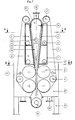
- Fig. 1 shows a twin filtering belt press constructed according to the invention.
- a mixture of solids and liquid is pumped through an inlet 12 into a prefiltering chamber 17.
- On the opposite walls of the chamber are located hole or slit plates 6, which converge, in other words, the surfaces thereof form a converging chamber therebetween and they support each their respective filtering belt 5 or filtering wire, which slides along the surface of the plate towards the direction of convergence of the chamber.
- the pumping pressure liquid flows first on both sides of the chamber through the wire 5 and the plate 6 into filtrate spaces 7 and 8 located on the opposite side of the plate.
- the spaces are located one after the other, as seen in the direction of travel of the wire, and they are separated from each other.
- the prefiltering chamber 17 converges in the direction of travel of the wires in such a fashion that the cakes 18 deposited onto the surfaces of the wires start to become squeezed against each other in the end portion of the chamber and seal the chamber 17 at its exit end.
- This sealing effect is further ensured by strips 22, shown in Fig. 3, which press the edges of the filtering wire together before the pressing stage. The strips will be described hereinafter in more detail.
- Both filtering wires 5 form endless wire loops, where the wire situated within the free portion is continously washed by means of shower tubes 11.
- a partition wall 19 is located between the consecutive filtrate chambers 7 and 8. It is thus possible to withdraw from the device different filtrates having a varying degree of purity.
- the purest filtrate emerges as a rule from a later filtering stage.
- the number of filtrate chambers can be one, two or several on both sides of the prefiltering camber 17.
- the filtrate exits from the filtrate chambers 7 and 8 through filtrate outlets 9, 10. Through these outlets the chambers can be provided with reduced pressure in order to make the filtration more effective.
- the cake deposited at the filtering stage is squeezed to a higher dryness by means of press rollers 3 located after the prefiltering chamber, this being done at one or several stages. After the press rollers 3 the cake pressed dry falls down into a conveyor 15.
- the filtrate formed at the pressing stage and the wash water of the wire is collected into a basin 20 and it exits throug an outlet 16.
- an inlet 13 another material to be filtrated can be pumped into the filtering chamber.
- This material may consist of not easily filterable solids/liquid mixtures, such as biosludge and circulation water.
- the solids therein will be filtered on top of a pre-coat cake being formed previously on the surface of the wire.
- Said inlet is located in the direction of travel of the wires 5 after the supply inlet 12.
- the press rollers 3 act mainly as the driving rollers running the filtering wires 5.
- the travel of a wire is further enhanced and guided within the free section of the wires by guide rollers 4 and by so-called reversing rollers 2, which quide the free run of the wires to the beginning of the prefiltering chamber 17.
- the whole device, including its prefiltering chamber, filtrate chambers and rollers, is mounted on a main frame construction 21.
- Fig. 2 shows the cross-section of the device taken along the plane A-A of Fig. 1, that is, at the location of the prefiltering chamber.
- the prefiltering chamber 17 and the filtrate chambers 7 on both sides thereof are arranged in a substantially closed housing-like construction 1.
- the dewatering surfaces are constituted of slitted plates or hole plates 6, along the surfaces of which the wires 5 pervious to water slide.
- the prefiltering chamber 17 is defined laterally, that is in the direction of the edges of the wires 5, by rigid walls 1a, which are fixedly joined to said plates 6.
- the edges of the wires 5 lie at a short distance from the respective wall 1a, this arrangement affording both well-sealed construction of the prefiltering chamber and a construction where edges of the wires are not subjected to wear.
- Both the opposite, parallel side walls 1a for the prefiltering chamber 17 continue in the direction of the filtrate chambers 7, 8 as the same walls, which form on the side of the filtrate chambers a wall defining the filtrate chamber.
- the plates 6 are thus fixed between the inner surfaces of the side walls 1a of the housing-like construction 1.
- To these side walls 1a are perpendicularly joined rear walls 1b defining the chambers.
- Fig. 2 further shows, how the width L2 of the liquid withdrawing area on the plates 6, that is, the width of the area wherein the holes or slits are situated, is substantially smaller than the width L1 of the wire 5 lying against it, in which case the edges of the wire 5 extend sideways substantially farther than the corresponding side edge of the liquid withdrawing area L2 at both edges. Due to this fact the solid cakes 18 formed on top of the filtering wires 5 are slightly wider than the liquid withdrawing area L2, but their width is still considerably smaller than width L1 of the corresponding filtering wire 5.
- L-L1 wherein L is the total width of the plate 6 restricted by the prefiltering chamber 17, may be 1 to 4 cm.
- the value of (L1-L2)/2 is preferably in the range of 5 to 15 cm, depending on the filterability of the solid cake formed by the suspension which is to filterd.
- Fig. 3 shows the cross-section of the device taken along the plane B-B of Fig. 1, that is, at the location of the exit end of the prefiltering chamber, where the ends of the hole plates or slitted plates 6 guide the wires 5 and the cake 18 squeezed between the wires at the exit end of the filtering chamber 17 in between the press rollers 3.
- both opposite plates 6 are provided with strips 22 protruding from their elsewhere flat surface and having a cross-section of a circle segment. The strips are situated laterally outside the dewatering area L2, but within the width L1 of the wires in both margin areas of the wire 5.
- the strips 22 act as sealing strips, whose arcuate surfaces raise the edges of the wires 5 off from the level of the dewatering surfaces of the plates 6 and press the edges of the opposite wires against each other at the location of the margin area of the wire situated a short distance inwardly from the outer edge of the wire 5. Because the cake formed by the against each other squeezed cakes 18 at the exit end of the prefiltering chamber 17 is of less width than the wires to a sufficient extent, it will be easily entrapped between the wires in the above-mentioned way in such a fashion that the cake does not become spread to the edges of the wires. The cake is denoted by a hatching between the wires 5 in Fig. 3. The edges of the wires 5 can be easily guided against each other at the exit end of the prefiltering chamber 17 in the above-described fashion.
- Fig. 3 further shows, how within the area of the strips 22 the side walls 1a of the prefiltering chamber are rigidly fixed to the longitudinal edges of the plates 6.
- the strips 22 and the plates 6 supporting them continue to as close to the press rollers 3 as possible.
- the cake is solid to such an extent that the sealing at the sides is no more necessary.
- the closed construction of the device makes it possible to design it so that it is operative in an upright position as shows in Fig. 1.
- the flow of the solids takes place downwards in this case, but an opposite flow direction is also possible.
- a horizontal construction and a horizontal flow direction are possible as well.
- the invention is applicable to the filtration of all suspensions containing solid substances, such as suspensions containing fibres, also irrespective of whether the solids or the filtrate is the more valuable material to be recovered.
- solid substances such as suspensions containing fibres
- the invention can also be used as a web forming device, the raw material of which is a fibrous suspension.
Landscapes
- Chemical & Material Sciences (AREA)
- Chemical Kinetics & Catalysis (AREA)
- Filtration Of Liquid (AREA)
- Electrical Discharge Machining, Electrochemical Machining, And Combined Machining (AREA)
- Treatment Of Sludge (AREA)
- Centrifugal Separators (AREA)
- Transition And Organic Metals Composition Catalysts For Addition Polymerization (AREA)
- Structure Of Belt Conveyors (AREA)
Applications Claiming Priority (2)
| Application Number | Priority Date | Filing Date | Title |
|---|---|---|---|
| FI885739A FI81965C (fi) | 1988-12-09 | 1988-12-09 | Anordning foer avskiljning av fasta aemnen fraon en suspension. |
| FI885739 | 1988-12-09 |
Publications (3)
| Publication Number | Publication Date |
|---|---|
| EP0377824A2 true EP0377824A2 (fr) | 1990-07-18 |
| EP0377824A3 EP0377824A3 (fr) | 1991-11-21 |
| EP0377824B1 EP0377824B1 (fr) | 1994-05-18 |
Family
ID=8527548
Family Applications (1)
| Application Number | Title | Priority Date | Filing Date |
|---|---|---|---|
| EP89122366A Expired - Lifetime EP0377824B1 (fr) | 1988-12-09 | 1989-12-05 | Dispositif de séparation de solides d'une suspension |
Country Status (7)
| Country | Link |
|---|---|
| US (1) | US5128030A (fr) |
| EP (1) | EP0377824B1 (fr) |
| AT (1) | ATE105728T1 (fr) |
| CA (1) | CA2004782C (fr) |
| DE (1) | DE68915422T2 (fr) |
| FI (1) | FI81965C (fr) |
| NO (1) | NO174493C (fr) |
Families Citing this family (6)
| Publication number | Priority date | Publication date | Assignee | Title |
|---|---|---|---|---|
| DE4328977C2 (de) * | 1993-08-28 | 1997-08-14 | Heiko Dr Schwertner | Verfahren und Vorrichtung zur Trennung von Substanzen oder Substanzklassen aus flüssigen oder gasförmigen Substanzgemischen in einem Kammersystem |
| US20080041245A1 (en) * | 2004-07-07 | 2008-02-21 | Peter Judocus | Solids Removal Press, Method and Feed System |
| US7964105B2 (en) * | 2008-08-07 | 2011-06-21 | William Harris Moss | Method for improving belt press dewatering |
| CA2678834A1 (fr) * | 2009-09-14 | 2011-03-14 | Gea Houle Inc. | Separateur a fumier avec presse a rouleaux en cascade |
| EP3868722A1 (fr) * | 2020-02-20 | 2021-08-25 | Metso Sweden Ab | Ensemble de déshydratation |
| CN113524761B (zh) * | 2021-07-23 | 2022-09-02 | 周口师范学院 | 一种用于生物制药的高效分离纯化装置 |
Family Cites Families (15)
| Publication number | Priority date | Publication date | Assignee | Title |
|---|---|---|---|---|
| US1778342A (en) * | 1921-01-03 | 1930-10-14 | Robert M Thompson | Filter device |
| US1875075A (en) * | 1930-01-25 | 1932-08-30 | Masonite Corp | Liquid separation |
| US3867252A (en) * | 1966-04-20 | 1975-02-18 | Michal Skrabak | Twin-wire multi-ply paper making machine |
| US3381609A (en) * | 1966-06-20 | 1968-05-07 | Neil Malarkey Jr. | Filter press |
| DE1966230U (de) * | 1966-12-24 | 1967-08-17 | Hydromation Engineering Compan | Filtervorrichtung. |
| CH518727A (de) * | 1968-07-02 | 1972-02-15 | Gujer Hans | Vorrichtung zum Abdichten des Filterraumes zwischen zwei Filterflächen, insbesondere zwei umlaufenden Filterbändern |
| CH557194A (de) * | 1972-10-28 | 1974-12-31 | Bellmer Geb Kg Maschf | Filterpresse. |
| US3998149A (en) * | 1975-02-10 | 1976-12-21 | Malarkey Jr Neil | Filter belt and press |
| FI63077C (fi) * | 1977-09-21 | 1983-04-11 | Tampella Oy Ab | Foerfarande och anordning foer reglering av profilen av en fiberbana i en pappersmaskin |
| DE2751849C2 (de) * | 1977-11-19 | 1982-08-19 | Gerhard 7410 Reutlingen Lüttich | Schlammfilterpresse |
| DE2844715C2 (de) * | 1978-10-13 | 1986-01-30 | Albert 6680 Neunkirchen Bähr | Entwässerungseinrichtung für SChlämme und ähnliche Substanzen, insbesondere für Abwasserschlämme |
| US4244804A (en) * | 1979-01-15 | 1981-01-13 | Innova, Inc. | Slime and sludge dewatering |
| US4395331A (en) * | 1979-07-09 | 1983-07-26 | Ab Saffle Gjuteri And Mekaniska Verkstad | Apparatus for pressing liquid out of material containing liquid |
| AT385793B (de) * | 1985-12-19 | 1988-05-10 | Andritz Ag Maschf | Siebbandpresse |
| AT385791B (de) * | 1986-02-18 | 1988-05-10 | Andritz Ag Maschf | Einrichtung zur behandlung einer zwischen mindestens zwei endlosen siebbaendern od.dgl. foerdereinrichtungen gefuehrten material- bzw. stoffbahn |
-
1988
- 1988-12-09 FI FI885739A patent/FI81965C/fi active IP Right Grant
-
1989
- 1989-11-28 NO NO894731A patent/NO174493C/no unknown
- 1989-12-05 AT AT89122366T patent/ATE105728T1/de not_active IP Right Cessation
- 1989-12-05 EP EP89122366A patent/EP0377824B1/fr not_active Expired - Lifetime
- 1989-12-05 DE DE68915422T patent/DE68915422T2/de not_active Expired - Fee Related
- 1989-12-06 CA CA002004782A patent/CA2004782C/fr not_active Expired - Fee Related
-
1991
- 1991-08-09 US US07/745,953 patent/US5128030A/en not_active Expired - Lifetime
Also Published As
| Publication number | Publication date |
|---|---|
| EP0377824A3 (fr) | 1991-11-21 |
| FI885739A7 (fi) | 1990-06-10 |
| DE68915422D1 (de) | 1994-06-23 |
| FI885739A0 (fi) | 1988-12-09 |
| DE68915422T2 (de) | 1994-10-27 |
| US5128030A (en) | 1992-07-07 |
| FI81965B (fi) | 1990-09-28 |
| CA2004782C (fr) | 2001-04-10 |
| EP0377824B1 (fr) | 1994-05-18 |
| CA2004782A1 (fr) | 1990-06-09 |
| NO174493B (no) | 1994-02-07 |
| FI81965C (fi) | 1991-01-10 |
| NO174493C (no) | 1994-05-25 |
| NO894731D0 (no) | 1989-11-28 |
| ATE105728T1 (de) | 1994-06-15 |
| NO894731L (no) | 1990-06-11 |
Similar Documents
| Publication | Publication Date | Title |
|---|---|---|
| US3190451A (en) | Endless belt filter | |
| CA1054531A (fr) | Element filtrant a courroie sans fin enveloppant les aliments avant pressage | |
| EP0369611B1 (fr) | Appareil pour épaissir des suspensions de pâte à papier | |
| EP0377824B1 (fr) | Dispositif de séparation de solides d'une suspension | |
| GB1161079A (en) | Screening Apparatus for Screening Fibrous Material in Liquid Suspension. | |
| CA1202246A (fr) | Courroie filtre-presse pour liquides epais | |
| US4995988A (en) | Method and apparatus for thickening a slurry using a compression plate | |
| US4276168A (en) | Device for dewatering sludge | |
| US4456530A (en) | Apparatus for improving gravity dehydration in strainer belt presses | |
| RU1820846C (ru) | Способ обезвоживани в фильтропрессе | |
| CA1101726A (fr) | Traduction non-disponible | |
| US4178251A (en) | Apparatus for dehydration of sludge | |
| FI81725C (fi) | Foerfarande och anordning foer behandling av fibersuspension. | |
| EP0020101A1 (fr) | Bande filtrante sous vide comprenant des moyens d'étanchéité sous vide | |
| DE1223806B (de) | Bandfilter mit Vakuumsaugraum fuer das Filtrat unterhalb des oberen Trumes | |
| CA1230258A (fr) | Filtre-presse servant a l'epaississement de la pate cellulosique ou des boues | |
| US5591336A (en) | Apparatus for dewatering and or washing papermaking stock | |
| US2960233A (en) | Filter and filter medium therefor | |
| DE3600526A1 (de) | Membranfilterpresse | |
| SU1082458A1 (ru) | Ленточный фильтр-пресс | |
| US3469704A (en) | Slurry washing apparatus | |
| SU1346196A1 (ru) | Ленточный фильтр-пресс | |
| SU912217A1 (ru) | Фильтр непрерывного действи дл обезвоживани суспензии | |
| SU982729A1 (ru) | Барабанный вакуум-фильтр со сход щим полотном | |
| US914476A (en) | Filter-press plate. |
Legal Events
| Date | Code | Title | Description |
|---|---|---|---|
| PUAI | Public reference made under article 153(3) epc to a published international application that has entered the european phase |
Free format text: ORIGINAL CODE: 0009012 |
|
| AK | Designated contracting states |
Kind code of ref document: A2 Designated state(s): AT DE FR GB SE |
|
| PUAL | Search report despatched |
Free format text: ORIGINAL CODE: 0009013 |
|
| AK | Designated contracting states |
Kind code of ref document: A3 Designated state(s): AT DE FR GB SE |
|
| 17P | Request for examination filed |
Effective date: 19920521 |
|
| 17Q | First examination report despatched |
Effective date: 19920814 |
|
| GRAA | (expected) grant |
Free format text: ORIGINAL CODE: 0009210 |
|
| AK | Designated contracting states |
Kind code of ref document: B1 Designated state(s): AT DE FR GB SE |
|
| REF | Corresponds to: |
Ref document number: 105728 Country of ref document: AT Date of ref document: 19940615 Kind code of ref document: T |
|
| REF | Corresponds to: |
Ref document number: 68915422 Country of ref document: DE Date of ref document: 19940623 |
|
| ET | Fr: translation filed | ||
| EAL | Se: european patent in force in sweden |
Ref document number: 89122366.1 |
|
| PLBE | No opposition filed within time limit |
Free format text: ORIGINAL CODE: 0009261 |
|
| STAA | Information on the status of an ep patent application or granted ep patent |
Free format text: STATUS: NO OPPOSITION FILED WITHIN TIME LIMIT |
|
| 26N | No opposition filed | ||
| REG | Reference to a national code |
Ref country code: GB Ref legal event code: IF02 |
|
| PGFP | Annual fee paid to national office [announced via postgrant information from national office to epo] |
Ref country code: AT Payment date: 20061213 Year of fee payment: 18 Ref country code: SE Payment date: 20061213 Year of fee payment: 18 |
|
| PGFP | Annual fee paid to national office [announced via postgrant information from national office to epo] |
Ref country code: DE Payment date: 20061218 Year of fee payment: 18 |
|
| PGFP | Annual fee paid to national office [announced via postgrant information from national office to epo] |
Ref country code: GB Payment date: 20061221 Year of fee payment: 18 |
|
| PGFP | Annual fee paid to national office [announced via postgrant information from national office to epo] |
Ref country code: FR Payment date: 20061212 Year of fee payment: 18 |
|
| EUG | Se: european patent has lapsed | ||
| GBPC | Gb: european patent ceased through non-payment of renewal fee |
Effective date: 20071205 |
|
| PG25 | Lapsed in a contracting state [announced via postgrant information from national office to epo] |
Ref country code: AT Free format text: LAPSE BECAUSE OF NON-PAYMENT OF DUE FEES Effective date: 20071205 |
|
| PG25 | Lapsed in a contracting state [announced via postgrant information from national office to epo] |
Ref country code: SE Free format text: LAPSE BECAUSE OF NON-PAYMENT OF DUE FEES Effective date: 20071206 Ref country code: DE Free format text: LAPSE BECAUSE OF NON-PAYMENT OF DUE FEES Effective date: 20080701 |
|
| REG | Reference to a national code |
Ref country code: FR Ref legal event code: ST Effective date: 20081020 |
|
| PG25 | Lapsed in a contracting state [announced via postgrant information from national office to epo] |
Ref country code: GB Free format text: LAPSE BECAUSE OF NON-PAYMENT OF DUE FEES Effective date: 20071205 |
|
| PG25 | Lapsed in a contracting state [announced via postgrant information from national office to epo] |
Ref country code: FR Free format text: LAPSE BECAUSE OF NON-PAYMENT OF DUE FEES Effective date: 20071231 |