EP0377943A1 - Cathéter intra-utérin - Google Patents
Cathéter intra-utérin Download PDFInfo
- Publication number
- EP0377943A1 EP0377943A1 EP89310245A EP89310245A EP0377943A1 EP 0377943 A1 EP0377943 A1 EP 0377943A1 EP 89310245 A EP89310245 A EP 89310245A EP 89310245 A EP89310245 A EP 89310245A EP 0377943 A1 EP0377943 A1 EP 0377943A1
- Authority
- EP
- European Patent Office
- Prior art keywords
- catheter
- pressure
- distal end
- sensor
- electrical conductors
- Prior art date
- Legal status (The legal status is an assumption and is not a legal conclusion. Google has not performed a legal analysis and makes no representation as to the accuracy of the status listed.)
- Withdrawn
Links
- 239000010931 gold Substances 0.000 claims abstract description 6
- 229910052737 gold Inorganic materials 0.000 claims abstract description 6
- PCHJSUWPFVWCPO-UHFFFAOYSA-N gold Chemical compound [Au] PCHJSUWPFVWCPO-UHFFFAOYSA-N 0.000 claims abstract description 5
- 239000004020 conductor Substances 0.000 claims description 34
- 239000012530 fluid Substances 0.000 claims description 13
- 238000000034 method Methods 0.000 claims description 11
- XUIMIQQOPSSXEZ-UHFFFAOYSA-N Silicon Chemical compound [Si] XUIMIQQOPSSXEZ-UHFFFAOYSA-N 0.000 claims description 10
- 229910052710 silicon Inorganic materials 0.000 claims description 10
- 239000010703 silicon Substances 0.000 claims description 10
- -1 polyethylene Polymers 0.000 claims description 6
- 239000004698 Polyethylene Substances 0.000 claims description 5
- 229920000573 polyethylene Polymers 0.000 claims description 5
- 238000009413 insulation Methods 0.000 claims description 4
- 239000004593 Epoxy Substances 0.000 claims description 3
- 229910021421 monocrystalline silicon Inorganic materials 0.000 claims description 3
- 238000003780 insertion Methods 0.000 claims description 2
- 230000037431 insertion Effects 0.000 claims description 2
- 238000005304 joining Methods 0.000 claims description 2
- ZEMPKEQAKRGZGQ-AAKVHIHISA-N 2,3-bis[[(z)-12-hydroxyoctadec-9-enoyl]oxy]propyl (z)-12-hydroxyoctadec-9-enoate Chemical compound CCCCCCC(O)C\C=C/CCCCCCCC(=O)OCC(OC(=O)CCCCCCC\C=C/CC(O)CCCCCC)COC(=O)CCCCCCC\C=C/CC(O)CCCCCC ZEMPKEQAKRGZGQ-AAKVHIHISA-N 0.000 claims 1
- 239000012811 non-conductive material Substances 0.000 claims 1
- 210000004291 uterus Anatomy 0.000 abstract description 11
- 238000010276 construction Methods 0.000 abstract description 4
- 238000012544 monitoring process Methods 0.000 description 7
- 239000000463 material Substances 0.000 description 5
- 208000036029 Uterine contractions during pregnancy Diseases 0.000 description 4
- 230000001605 fetal effect Effects 0.000 description 3
- 210000002458 fetal heart Anatomy 0.000 description 3
- 210000003754 fetus Anatomy 0.000 description 3
- 101000679358 Brassica oleracea var. botrytis Triose phosphate/phosphate translocator, non-green plastid, chloroplastic Proteins 0.000 description 2
- 210000004381 amniotic fluid Anatomy 0.000 description 2
- 230000036772 blood pressure Effects 0.000 description 2
- 230000035606 childbirth Effects 0.000 description 2
- 238000002788 crimping Methods 0.000 description 2
- 229920006333 epoxy cement Polymers 0.000 description 2
- 239000007787 solid Substances 0.000 description 2
- 239000004743 Polypropylene Substances 0.000 description 1
- 229910000831 Steel Inorganic materials 0.000 description 1
- 238000013459 approach Methods 0.000 description 1
- 230000004872 arterial blood pressure Effects 0.000 description 1
- 229910000963 austenitic stainless steel Inorganic materials 0.000 description 1
- 239000005388 borosilicate glass Substances 0.000 description 1
- 230000001010 compromised effect Effects 0.000 description 1
- 239000013078 crystal Substances 0.000 description 1
- 230000010339 dilation Effects 0.000 description 1
- 238000006073 displacement reaction Methods 0.000 description 1
- 230000000694 effects Effects 0.000 description 1
- 238000001727 in vivo Methods 0.000 description 1
- 238000002955 isolation Methods 0.000 description 1
- 239000007788 liquid Substances 0.000 description 1
- 238000004519 manufacturing process Methods 0.000 description 1
- 230000013011 mating Effects 0.000 description 1
- 229940127554 medical product Drugs 0.000 description 1
- 239000004033 plastic Substances 0.000 description 1
- 229920003023 plastic Polymers 0.000 description 1
- 239000004417 polycarbonate Substances 0.000 description 1
- 229920000515 polycarbonate Polymers 0.000 description 1
- 229920001155 polypropylene Polymers 0.000 description 1
- 229920001296 polysiloxane Polymers 0.000 description 1
- 230000035935 pregnancy Effects 0.000 description 1
- 229910001220 stainless steel Inorganic materials 0.000 description 1
- 239000010935 stainless steel Substances 0.000 description 1
- 239000010959 steel Substances 0.000 description 1
- 239000000126 substance Substances 0.000 description 1
Images

Classifications
-
- A—HUMAN NECESSITIES
- A61—MEDICAL OR VETERINARY SCIENCE; HYGIENE
- A61B—DIAGNOSIS; SURGERY; IDENTIFICATION
- A61B5/00—Measuring for diagnostic purposes; Identification of persons
- A61B5/03—Measuring fluid pressure within the body other than blood pressure, e.g. cerebral pressure ; Measuring pressure in body tissues or organs
- A61B5/033—Uterine pressure
- A61B5/035—Intra-uterine probes therefor
Definitions
- This invention relates to a pressure sensing catheter and a method of making the same and, in particular, to an intrauterine catheter for sensing the amniotic fluid pressure within a woman during pregnancy.
- fetal activity such as fetal heart rate and intrauterine pressure as an indication of the overall well being of the fetus.
- monitors are available that measure the pressure within the uterus, detect uterine contractions or other pressure changes and also detect and monitor fetal heart rate.
- such intrauterine pressure monitors are external or internal.
- Tacodynamometers can be used externally and which measure the duration and frequency of uterine contractions.
- external monitoring is useful and convenient to utilize, it also suffers from difficulties in picking up and interpreting extraneous interference.
- the external interference such as motion and noise artifact increases as childbirth approaches and thus, external monitors of uterine contractions as well as fetal heart rate often have difficultly in obtaining accurate readings at the critical times that accuracy is needed.
- a pressure transducer is located external to the patient so as to measure the pressure in a column of fluid, one end of which is placed directly within the uterus and the other end is connected to the external transducer.
- the fluid is displaced in the catheter by pressure changes in the uterus and those changes in fluid displacement are sensed by a diaphragm in the pressure transducer and converted to electrical signals to be supplied to a monitor.
- the fluid filled catheter is introduced into the uterus by being threaded through an introducer or guide tube that in turn is positioned manually by the attending doctor.
- the fluid filled catheter itself is fitted through the introducer where it is moved forward into the desired position adjacent the fetus.
- Fluid filled catheters are more accurate in determining amniotic pressures since the catheter open end is directly placed at the location for which information is sought, however, such catheters also suffer from certain difficulties. They require a container of sterile liquid, valves, and can also be subject to motion artifact. In addition, problems arise by the presence of bubbles and the fluid filling procedures are relatively cumbersome to carry out.
- catheter tip pressure transducers have been developed wherein the pressure transducer itself is located in the catheter tip and thus directly measures and converts to electrical signals, the pressure within the uterus at the catheter tip.
- Typical devices utilize solid state piezoresistive crystals and which may be etched on one or both sides to form a flexible diaphragm in the electronic chip or die.
- a device of this type is shown and described in U.S. patent 4,726,232 of Koneval and such devices are readily manufacturable by, known methods.
- the electronic monocrystalline silicon piezoresistive die as described in the aforementioned U.S. patent may be referred to as the electronic sensor for brevity.
- Such electronic sensors essentially are minute strain guages and the amount of flexing of the etched diaphragm is indicative of the differential pressure across that diaphragm.
- a known, reference pressure such as atmospheric pressure
- CPT Catheter tip pressure transducer
- the catheter essentially has a large bulge at its end, the diameter increases over 200 percent.
- large diameter tubing is necessitated and integral stiffening wire.
- a large dilation is required for catheter placement on the order of 2 cm.
- a smaller overall catheter with a uniform sized tip is preferred, providing accuracy is not compromised.
- one of the recognized methods of introducing an intrauterine pressure catheter is by use of an introducer, as currently used with fluid-filled pressure catheters. Since many physicians are comfortable with the use of such introducers, they prefer to use that method of introduction.
- Introducers typically used are of the size 14 French which corresponds to an outer diameter of 0.104 inches and therefore a catheter such as the aforedescribed catheter cannot be used since the catheter tip containing the pressure transducer is too large and is non-uniform with respect to the catheter tubing.
- Cantilever beam devices adaptable for use in a catheter tip include Schaberg et al U.S. Patent 4,545,389 and Millar U.S. Patents 3,748,623 and 3,724,274.
- a catheter for measuring the pressure of a fluid within the body of a patient said catheter having a distal end for insertion into the body and a proximal end which in use remains outside the body is characterised in that said distal end includes a chamber having an opening, an electronic sensor mounted in said chamber and responsive to differential pressures across two surfaces thereof, said electronic sensor being sealed across the opening such that one of said surfaces is acted upon by pressure within the chamber whilst the other surface is acted upon by pressure external to said catheter, a passage in the catheter for introducing a known pressure to said chamber, electrical conductors having first ends terminating in external connections at the proximal end of the catheter and second ends terminating at said distal end within the chamber, device wiring means directly connecting said electrode sensor to said second ends of the electrical conductors at said distal end and in that said catheter is substantially uniform in outer dimensions.
- the catheter is comprised of a flexible tubing, preferably polyethyene, having a proximal end providing electrical connections and a distal end that includes a solid state electronic sensor mounted in a particular manner.
- the device is a known silicon chip strain gage type as shown and described in the aforementioned U.S. Patent 4,726,232 having dimensions of about .080 inches square.
- the electronic sensor device is mounted such that the overall outer diameter of the distal tip of the catheter containing the electronic sensor is preferably no larger than 3.3mm or a size 10 French with a catheter tubing preferably of about 3.0mm or size 9 French. Accordingly, the catheter may be introduced into the human body by means of an introducer and is relatively uniform by having its distal tip diameter of approximately 10 percent larger than the catheter tubing outside diameter.
- a special catheter tip is constructed wherein electrical wires are directly formed between the pads of the sensor and the free ends of ribbon cable that passes through the catheter from electrical connector located at the proximal end, thus greatly reducing the size requirements by eliminating any intermediate printed circuit boards or other connection means.
- the outside diameter of the distal end of the catheter is reduced, with respect to the prior art, by affixing the electronic sensor directly to a frame such that one side of the electronic sensor is directly associated with the pressure sought to be sensed while the other side is acted upon by a known pressure within a chamber formed in the distal end.
- That chamber is created by a thin cylindrical sleeve that surrounds the frame and which sleeve is crimped to the end of the flexible tubing.
- Various seals are made at surfaces covered by the sleeve and the sleeve itself may be typically as small as 3.3mm in outer diameter and crimped to a flexible tubing having an outside diameter of about 3.0mm, thus the outer dimension of the entire catheter does not vary by more than about ten percent, throughout its entire length. Due to the particular construction, the overall intrauterine catheter is reduced in size with respect to the prior art catheters, is sufficiently flexible without kinking, and can be introduced into the uterus by means of introducers of conventional size internal and external diameters.
- FIG. 1 there is shown a side view of an intrauterine pressure transducer catheter 10 constructed in accordance with the present invention.
- the catheter 10 comprises flexible tubing 12, preferably of polypropylene or polyethylene.
- the material requires certain flexibility yet, obviously, must be bio-compatible with the body where pressures are being measured.
- Catheter 10 further includes a proximal end 14 that, in use, remains outside the body and has an electrical connector 16 for connection to a mating connector for wiring to a monitor to display the pressures being monitored.
- a distal end 18 is located at the other end of catheter 10 and is inserted into the body to be positioned at the very location therein where pressure determinations are desired.
- FIG. 2 is a plan view, partially broken away and Figure 3 is an enlarged side cross-sectional view of the distal end 18 of catheter 10.
- tubular frame 20 is affixed to the end of flexible tubing 12.
- tubular frame 20 includes a reduced diameter cylindrical projecting stem 22 that is fitted within the internal diameter of flexible tubing 12 to affix tubular frame 20 thereto.
- at least one barb 24 is formed at or near the projecting end of projecting stem 22 and which firmly grips the internal surface of flexible tubing 12.
- Tubular frame 20 includes an cylindrical bore 26 that communicates with the interior hollow opening 28 running through the length of flexible tubing 12.
- the tubular frame 20 is made of rigid material and can include stainless steel or a plastic such as polycarbonate.
- a cylindrical sleeve 30 surrounds tubular frame 20 and is secured to the outer diameter of flexible tubing 12. That securing means is provided by crimping the open end 31 of cylindrical sleeve 30 about flexible tubing 12. Cylindrical sleeve 30 must be a material of sufficent hardness, yet bio-compatible with the human body, thus, a preferred material is austenitic stainless steel. Therefore, physical crimping is utilized in view of the difficulty of achieving a bond between austenitic steel and the preferred polyethylene material of flexible tubing 12.
- the outer diameter of cylindrical sleeve 30 is only slightly larger than the outer diameter of flexible tubing 12; in the preferred embodiment, the outer diameter of cylindrical sleeve 30 may be about 3.3mm, being equivalent to a size 10 French, while the flexible tubing 12 has an outer diameter of about 3.0mm; or equivalent to a size 9 French.
- the two outer diameters are substantually the same with an increase or difference in diameter being in the range of 10 percent.
- a cut away area 32 is formed in tubular frame 20 and which forms a chamber 34 within the cylindrical sleeve 30. That cut away area 32 is formed such as to create a first flat area 36 and which has an aperture 38 therethrough.
- a pressure transducer is mounted to the first flat area 36 and comprises a monocrystalline silicon piezoresistor sensor 40 anodically bonded to a borosilicate glass isolator 42.
- the sensor 40 is of a type commonly used in blood pressure transducers and specifically can be made as disclosed in U.S. Patent 4,726,232, it being noted that, in the present invention, such sensors can conventionally be made having dimensions of about .080 inches square.
- the senor 40 has one surface thereof directly acted upon by the pressure in chamber 34 and its other surface is acted upon by pressures external to catheter 10 through the aperture 38 in tubular frame 20 and corresponding aperture 44 in cylindrical sleeve 30.
- a fluid dielectric medium 46 fills aperture 38 and may be silicone gel to provide electrical and chemical isolation of sensor 40 yet transmit pressure of the amniotic fluid being measured external of catheter 10 within the uterus.
- a second flat area 48 is formed in tubular frame 20 and is used to make electrical connections between ribbon cable 50 and sensor 40.
- ribbon cable 50 is connected at one end to the electrical connector 16 located at the proximal end 14 of catheter 10 and has its other free end 52 terminating within chamber 34 at the distal end 18 of catheter 10.
- ribbon cable 50 may pass within the hollow opening 28 in flexible tubing 12 and is a multi-conductor cable covered by insulation, normally a four conductor cable where the individual conductors may have an outside diameter of about 0.005 inches.
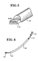
- the free end 52 of ribbon cable 50 is first flattened as shown in the perspective view of Figure 5.
- the amount of flattening needs to be sufficient to provide an upper surface of each conductor cable having a width of about 0.006 inches.
- the free end 52 is twisted backward and affixed to second flat area 48 by means such as an epoxy cement.
- an instrument is used to scrape the upper insulation from the multi-conductor ribbon cable 50 such that all of the conductors have bare upper surfaces 54 ( Figure 4).
- Connection can now be accomplished directly from the conductor pads 56 of the sensor 40 to the bared, flattened upper surfaces 54 of free end 52 of ribbon cable 50 by means of a conventional gold wedge bonding machine to create a gold wedge bond 58 between the conductive pads 56 and upper surfaces 54 of the individual conductors of ribbon cable 50.
- the distal end 60 of tubular frame 20 can be sealed by an epoxy plug 62 which also seals against cylindrical sleeve 30.
- cylindrical sleeve 30 may be deep drawn and have a closed end such that the epoxy plug 62 would not be necessary. Additional epoxy cement may be applied about the periphery of the aperture 44 of cylindrical sleeve 30 to seal therearound as well as between cylindrical sleeve 30 and the outer surface of tubular frame 20 to prevent pressure leaks or movement between those components.
- FIG 6 there is shown a perspective view of catheter 10 constructed in accordance of the present invention inserted through an introducer 64.
- a physician manually locates the distal end 66 of introducer 64 at the entrance to the uterus and then guides the catheter 10 through the introducer 64 such that the distal end 18 reaches the desired position for monitoring the intrauterine pressure adjacent the fetus.
- introducer 64 may be of the splittable type that is removed after placement of the catheter, by splitting the introducer longitudinally and removing it entirely.
Landscapes
- Health & Medical Sciences (AREA)
- Life Sciences & Earth Sciences (AREA)
- Heart & Thoracic Surgery (AREA)
- Medical Informatics (AREA)
- Biophysics (AREA)
- Pathology (AREA)
- Engineering & Computer Science (AREA)
- Biomedical Technology (AREA)
- Hematology (AREA)
- Physics & Mathematics (AREA)
- Molecular Biology (AREA)
- Surgery (AREA)
- Animal Behavior & Ethology (AREA)
- General Health & Medical Sciences (AREA)
- Public Health (AREA)
- Veterinary Medicine (AREA)
- Measuring And Recording Apparatus For Diagnosis (AREA)
- Media Introduction/Drainage Providing Device (AREA)
Applications Claiming Priority (2)
| Application Number | Priority Date | Filing Date | Title |
|---|---|---|---|
| US29507489A | 1989-01-09 | 1989-01-09 | |
| US295074 | 1989-01-09 |
Publications (1)
| Publication Number | Publication Date |
|---|---|
| EP0377943A1 true EP0377943A1 (fr) | 1990-07-18 |
Family
ID=23136100
Family Applications (1)
| Application Number | Title | Priority Date | Filing Date |
|---|---|---|---|
| EP89310245A Withdrawn EP0377943A1 (fr) | 1989-01-09 | 1989-10-06 | Cathéter intra-utérin |
Country Status (3)
| Country | Link |
|---|---|
| EP (1) | EP0377943A1 (fr) |
| JP (1) | JPH02203837A (fr) |
| AU (1) | AU3992289A (fr) |
Cited By (3)
| Publication number | Priority date | Publication date | Assignee | Title |
|---|---|---|---|---|
| EP0766946A3 (fr) * | 1995-09-22 | 1997-05-02 | Graphic Controls Corporation | Système à sonde de mesure de la pression intrautérine comportant un transducteur à extrémité |
| EP1671669A1 (fr) * | 2004-12-15 | 2006-06-21 | Nitto Denko Corporation | Cathéter comprenant un circuit imprimé flexible et son procédé de fabrication |
| CN115382080A (zh) * | 2022-08-16 | 2022-11-25 | 上海颖特微络医疗科技有限公司 | 具有测压功能的导管、腔内治疗导管和智能腔内治疗装置 |
Families Citing this family (2)
| Publication number | Priority date | Publication date | Assignee | Title |
|---|---|---|---|---|
| TW221491B (fr) * | 1990-03-16 | 1994-03-01 | Matsushita Electric Industrial Co Ltd | |
| US5713351A (en) * | 1995-11-20 | 1998-02-03 | Utah Medical Products, Inc. | Intrauterine meconium detection system |
Citations (6)
| Publication number | Priority date | Publication date | Assignee | Title |
|---|---|---|---|---|
| US4023562A (en) * | 1975-09-02 | 1977-05-17 | Case Western Reserve University | Miniature pressure transducer for medical use and assembly method |
| US4274423A (en) * | 1977-12-15 | 1981-06-23 | Kabushiki Kaisha Toyota Chuo Kenkyusho | Catheter tip pressure transducer |
| US4722348A (en) * | 1985-09-17 | 1988-02-02 | Sentron V.O.F. | Catheter tip pressure transducer |
| US4726232A (en) * | 1986-06-02 | 1988-02-23 | Gould Inc. | Temperature coefficient compensated pressure transducer |
| EP0263190A1 (fr) * | 1986-10-02 | 1988-04-13 | Dräger Nederland B.V. | Convertisseur de pression destiné aux applications médicales |
| US4785822A (en) * | 1987-04-01 | 1988-11-22 | Utah Medical Products, Inc. | Disposable intracompartmental pressure transducer |
Family Cites Families (2)
| Publication number | Priority date | Publication date | Assignee | Title |
|---|---|---|---|---|
| US4252131A (en) * | 1978-04-17 | 1981-02-24 | American Home Products Corporation | Catheter for measuring intrauterine pressure |
| JPS60249934A (ja) * | 1984-05-28 | 1985-12-10 | 住友ベークライト株式会社 | 圧力センサ− |
-
1989
- 1989-08-16 AU AU39922/89A patent/AU3992289A/en not_active Abandoned
- 1989-10-06 EP EP89310245A patent/EP0377943A1/fr not_active Withdrawn
- 1989-12-11 JP JP32125789A patent/JPH02203837A/ja active Pending
Patent Citations (6)
| Publication number | Priority date | Publication date | Assignee | Title |
|---|---|---|---|---|
| US4023562A (en) * | 1975-09-02 | 1977-05-17 | Case Western Reserve University | Miniature pressure transducer for medical use and assembly method |
| US4274423A (en) * | 1977-12-15 | 1981-06-23 | Kabushiki Kaisha Toyota Chuo Kenkyusho | Catheter tip pressure transducer |
| US4722348A (en) * | 1985-09-17 | 1988-02-02 | Sentron V.O.F. | Catheter tip pressure transducer |
| US4726232A (en) * | 1986-06-02 | 1988-02-23 | Gould Inc. | Temperature coefficient compensated pressure transducer |
| EP0263190A1 (fr) * | 1986-10-02 | 1988-04-13 | Dräger Nederland B.V. | Convertisseur de pression destiné aux applications médicales |
| US4785822A (en) * | 1987-04-01 | 1988-11-22 | Utah Medical Products, Inc. | Disposable intracompartmental pressure transducer |
Cited By (4)
| Publication number | Priority date | Publication date | Assignee | Title |
|---|---|---|---|---|
| EP0766946A3 (fr) * | 1995-09-22 | 1997-05-02 | Graphic Controls Corporation | Système à sonde de mesure de la pression intrautérine comportant un transducteur à extrémité |
| EP1671669A1 (fr) * | 2004-12-15 | 2006-06-21 | Nitto Denko Corporation | Cathéter comprenant un circuit imprimé flexible et son procédé de fabrication |
| US7632236B2 (en) | 2004-12-15 | 2009-12-15 | Nitto Denko Corporation | Catheter and production method thereof |
| CN115382080A (zh) * | 2022-08-16 | 2022-11-25 | 上海颖特微络医疗科技有限公司 | 具有测压功能的导管、腔内治疗导管和智能腔内治疗装置 |
Also Published As
| Publication number | Publication date |
|---|---|
| AU3992289A (en) | 1990-07-12 |
| JPH02203837A (ja) | 1990-08-13 |
Similar Documents
| Publication | Publication Date | Title |
|---|---|---|
| US5184619A (en) | Intrauterine pressure and fetal heart rate sensor | |
| US4785822A (en) | Disposable intracompartmental pressure transducer | |
| EP0419294B1 (fr) | Dispositif support pour un capteur à cathéter et procédé d'application | |
| US4873986A (en) | Disposable apparatus for monitoring intrauterine pressure and fetal heart rate | |
| EP0492837B1 (fr) | Appareil qui montre un capteur sur un raccord pour cathéter | |
| US6115624A (en) | Multiparameter fetal monitoring device | |
| US8419647B2 (en) | Ultra miniature pressure sensor | |
| JP3881037B2 (ja) | 使い捨てドームを備えた圧力変換器装置 | |
| US6264612B1 (en) | Catheter with mechano-responsive element for sensing physiological conditions | |
| EP0047986A2 (fr) | Transducteur de pression étanche, à circuits intégrés, pour implantation | |
| JP3157834B2 (ja) | 較正ポートを有するトランスデューサ・ハウジング | |
| CA2115712A1 (fr) | Catheter pour surveillance de la pression intrauterine | |
| JP6619845B2 (ja) | センサ素子、センサ・ワイヤ、およびセンサ素子の製造方法 | |
| US3662743A (en) | Pressure transducer for catheter pressure measurement | |
| EP0377943A1 (fr) | Cathéter intra-utérin | |
| JPH0341684Y2 (fr) |
Legal Events
| Date | Code | Title | Description |
|---|---|---|---|
| PUAI | Public reference made under article 153(3) epc to a published international application that has entered the european phase |
Free format text: ORIGINAL CODE: 0009012 |
|
| AK | Designated contracting states |
Kind code of ref document: A1 Designated state(s): DE FR GB IT NL SE |
|
| 17P | Request for examination filed |
Effective date: 19910117 |
|
| 17Q | First examination report despatched |
Effective date: 19930113 |
|
| STAA | Information on the status of an ep patent application or granted ep patent |
Free format text: STATUS: THE APPLICATION IS DEEMED TO BE WITHDRAWN |
|
| 18D | Application deemed to be withdrawn |
Effective date: 19930525 |