EP0377979A1 - Tuyau pour le transport pneumatique de particules de polymère - Google Patents
Tuyau pour le transport pneumatique de particules de polymère Download PDFInfo
- Publication number
- EP0377979A1 EP0377979A1 EP89313117A EP89313117A EP0377979A1 EP 0377979 A1 EP0377979 A1 EP 0377979A1 EP 89313117 A EP89313117 A EP 89313117A EP 89313117 A EP89313117 A EP 89313117A EP 0377979 A1 EP0377979 A1 EP 0377979A1
- Authority
- EP
- European Patent Office
- Prior art keywords
- pipe
- restriction
- sectional area
- polymer particles
- polymer
- Prior art date
- Legal status (The legal status is an assumption and is not a legal conclusion. Google has not performed a legal analysis and makes no representation as to the accuracy of the status listed.)
- Ceased
Links
- 229920000642 polymer Polymers 0.000 title claims abstract description 46
- 239000002245 particle Substances 0.000 title claims abstract description 27
- 239000012159 carrier gas Substances 0.000 claims abstract description 13
- 238000002844 melting Methods 0.000 claims abstract description 6
- 230000008018 melting Effects 0.000 claims abstract description 6
- 239000007787 solid Substances 0.000 claims abstract description 6
- 239000000203 mixture Substances 0.000 claims abstract description 5
- 239000008187 granular material Substances 0.000 claims description 12
- 238000000034 method Methods 0.000 claims description 9
- IJGRMHOSHXDMSA-UHFFFAOYSA-N Atomic nitrogen Chemical compound N#N IJGRMHOSHXDMSA-UHFFFAOYSA-N 0.000 claims description 8
- 229910052757 nitrogen Inorganic materials 0.000 claims description 4
- 239000011324 bead Substances 0.000 claims description 3
- 239000007789 gas Substances 0.000 claims description 3
- 239000000843 powder Substances 0.000 claims description 3
- 239000004793 Polystyrene Substances 0.000 claims description 2
- QVGXLLKOCUKJST-UHFFFAOYSA-N atomic oxygen Chemical compound [O] QVGXLLKOCUKJST-UHFFFAOYSA-N 0.000 claims description 2
- 239000001257 hydrogen Substances 0.000 claims description 2
- 229910052739 hydrogen Inorganic materials 0.000 claims description 2
- 239000000178 monomer Substances 0.000 claims description 2
- 239000001301 oxygen Substances 0.000 claims description 2
- 229910052760 oxygen Inorganic materials 0.000 claims description 2
- 229920000728 polyester Polymers 0.000 claims description 2
- 229920000098 polyolefin Polymers 0.000 claims description 2
- 229920002223 polystyrene Polymers 0.000 claims description 2
- 229920000915 polyvinyl chloride Polymers 0.000 claims description 2
- 239000004800 polyvinyl chloride Substances 0.000 claims description 2
- XLYOFNOQVPJJNP-UHFFFAOYSA-N water Substances O XLYOFNOQVPJJNP-UHFFFAOYSA-N 0.000 claims description 2
- UFHFLCQGNIYNRP-UHFFFAOYSA-N Hydrogen Chemical compound [H][H] UFHFLCQGNIYNRP-UHFFFAOYSA-N 0.000 claims 1
- 229930195733 hydrocarbon Natural products 0.000 claims 1
- 150000002430 hydrocarbons Chemical class 0.000 claims 1
- 230000015572 biosynthetic process Effects 0.000 description 6
- 230000015556 catabolic process Effects 0.000 description 3
- 238000006731 degradation reaction Methods 0.000 description 3
- 229920000092 linear low density polyethylene Polymers 0.000 description 3
- 239000004707 linear low-density polyethylene Substances 0.000 description 3
- -1 polypropylene Polymers 0.000 description 3
- VGGSQFUCUMXWEO-UHFFFAOYSA-N Ethene Chemical compound C=C VGGSQFUCUMXWEO-UHFFFAOYSA-N 0.000 description 2
- 239000005977 Ethylene Substances 0.000 description 2
- 239000004743 Polypropylene Substances 0.000 description 2
- 239000004411 aluminium Substances 0.000 description 2
- 229910052782 aluminium Inorganic materials 0.000 description 2
- XAGFODPZIPBFFR-UHFFFAOYSA-N aluminium Chemical compound [Al] XAGFODPZIPBFFR-UHFFFAOYSA-N 0.000 description 2
- 238000006243 chemical reaction Methods 0.000 description 2
- 229920001577 copolymer Polymers 0.000 description 2
- 230000000694 effects Effects 0.000 description 2
- 229920001684 low density polyethylene Polymers 0.000 description 2
- 239000004702 low-density polyethylene Substances 0.000 description 2
- 238000004519 manufacturing process Methods 0.000 description 2
- 239000000155 melt Substances 0.000 description 2
- 229910052751 metal Inorganic materials 0.000 description 2
- 239000002184 metal Substances 0.000 description 2
- 229920001155 polypropylene Polymers 0.000 description 2
- 229920002943 EPDM rubber Polymers 0.000 description 1
- 239000004698 Polyethylene Substances 0.000 description 1
- 229910000831 Steel Inorganic materials 0.000 description 1
- 239000000654 additive Substances 0.000 description 1
- 239000000956 alloy Substances 0.000 description 1
- 229910045601 alloy Inorganic materials 0.000 description 1
- 239000003795 chemical substances by application Substances 0.000 description 1
- VXNZUUAINFGPBY-UHFFFAOYSA-N ethyl ethylene Natural products CCC=C VXNZUUAINFGPBY-UHFFFAOYSA-N 0.000 description 1
- 230000005484 gravity Effects 0.000 description 1
- 229920001903 high density polyethylene Polymers 0.000 description 1
- 239000004700 high-density polyethylene Substances 0.000 description 1
- 125000004435 hydrogen atom Chemical class [H]* 0.000 description 1
- 229920005684 linear copolymer Polymers 0.000 description 1
- 229920001083 polybutene Polymers 0.000 description 1
- 229920000573 polyethylene Polymers 0.000 description 1
- 238000006116 polymerization reaction Methods 0.000 description 1
- QQONPFPTGQHPMA-UHFFFAOYSA-N propylene Natural products CC=C QQONPFPTGQHPMA-UHFFFAOYSA-N 0.000 description 1
- 125000004805 propylene group Chemical group [H]C([H])([H])C([H])([*:1])C([H])([H])[*:2] 0.000 description 1
- 229920006395 saturated elastomer Polymers 0.000 description 1
- 229930195734 saturated hydrocarbon Natural products 0.000 description 1
- 239000010935 stainless steel Substances 0.000 description 1
- 229910001220 stainless steel Inorganic materials 0.000 description 1
- 239000010959 steel Substances 0.000 description 1
- 229930195735 unsaturated hydrocarbon Natural products 0.000 description 1
Images
Classifications
-
- B—PERFORMING OPERATIONS; TRANSPORTING
- B65—CONVEYING; PACKING; STORING; HANDLING THIN OR FILAMENTARY MATERIAL
- B65G—TRANSPORT OR STORAGE DEVICES, e.g. CONVEYORS FOR LOADING OR TIPPING, SHOP CONVEYOR SYSTEMS OR PNEUMATIC TUBE CONVEYORS
- B65G53/00—Conveying materials in bulk through troughs, pipes or tubes by floating the materials or by flow of gas, liquid or foam
- B65G53/34—Details
- B65G53/52—Adaptations of pipes or tubes
- B65G53/521—Adaptations of pipes or tubes means for preventing the accumulation or for removal of deposits
Definitions
- the present invention relates to a novel pipe suitable for the pneumatic transport of polymer particles and to a pneumatic transport process.
- polymer particles such as powders, beads or granules
- transport polymer particles such as powders, beads or granules
- These polymer particles are transported with the aid of a carrier gas in a pipeline consisting of a system of pipes characterized by a constant cross-section and more particularly by a circular section of constant diameter.
- a carrier gas in a pipeline consisting of a system of pipes characterized by a constant cross-section and more particularly by a circular section of constant diameter.
- threads or filaments disturbing the transport and the conversion of this polymer, is observed inside the pipelines.
- the formation of threads or filaments is essentially due to degradation or crumbling of the polymer particles.
- the pipes can have, on their internal surface, circular or helical notches which can be made with the aid of a special device moving inside these pipes. It is thus impossible to produce such pipes in an already existing plant.
- the notches can fill with polymer particles and can therefore lose their effect on the transport of the particles.
- the polymer transported in such pipes can be contaminated by another polymer, of a different quality, which has previously been transported in these pipes.
- a novel pipe for the pneumatic transport of solid polymer particles has now been found which makes it possible to overcome the disadvantages mentioned above.
- it avoids the formation of polymer threads or filaments, especially when it is used to transport a hot polymer or to transport a polymer by means of a hot carrier gas.
- This novel pipe has the attraction of being easy to produce with the aid of a simple device.
- the invention has the added attraction that pipes of an already existing plant can be easily modified to form pipes according to the invention.
- the present invention therefore relates to a cylindrical pipe of internal diameter d, intended for the pneumatic transport of solid polymer particles, characterized in that it has constrictions located over its length in such a way that the distance 1 between two consecutive constrictions is between d and 10 x d.
- the distance 1 between two consecutive constrictions is essential for the distance 1 between two consecutive constrictions to be short enough to avoid the formation of threads or filaments.
- the distance 1 is generally between d and 10 x d and preferably between 1.5 x d and 5 x d.
- the constrictions are located at regular intervals over the length of the pipe and are a constant distance 1 apart.
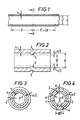
- Figure 1 schematically represents a longitudinal section of a cylindrical pipe according to the present invention, the said pipe having a thickness e and an internal diameter d and having constrictions located at regular intervals and a distance 1 apart, 1 being equal to 2 x d.
- a constriction consists of a restriction of the internal circular cross-sectional area S ofthe pipe.
- the new internal cross-sectional area S′ of the pipe which is useful for the passage of the polymer, can advantageously be between 0.900 x S and 0.995 x S and more particularly between 0.95 x S and 0.99 x S.
- a constriction is produced symmetrically to the longitudinal axis of the cylindrical pipe.
- the appearance of mechanical stresses, which may cause the pipe to deform, can thus be avoided when the pipe is made. Consequently, at each constriction of this type, an internal cross-sectional area S′ is obtained which is symmetrical relative to the longitudinal axis of the pipe.
- a constriction in the cylindrical pipe can consist in particular of a symmetrical and uniform restriction of the circular cross-sectional area S so as to give a new circular cross-sectional area S′ concentric with the area S.
- This type of constriction is particularly suitable for a pipe arranged vertically in a plant for the pneumatic transport of polymer.
- Figure 3 schematically represents a constriction consisting of a symmetrical and uniform restriction, in a cross-section of a pipe having a thickness e and an internal diameter d. This constriction defines a circular cross-sectional area S′ of diameter d′.
- the constriction in the cylindrical pipe can also consist of a non-uniform restriction of the circular area S.
- it can be produced so as to give a surface S′ having a restricted part and one or more unrestricted free passages defined by circular sectors of the area S.
- the circular sectors have a vertex situated on the axis of the pipe and an angle at the vertex ranging from 5° to 60°.
- This type of constriction having at least one unrestricted passage is suitable for any pipe of a plant for the pneumatic transport of polymer.
- this type of constriction is particularly recommended for a horizontal or inclined pipe such that the axis of the pipe forms an angle of less than about 80° with the horizontal plane.
- an unrestricted free passage is advantageously located at the lowest point of each constriction.
- the effect of the restricted part is to stop or slow down the particles, which then tend to fall under gravity to the lowest point of the constriction.
- the unrestricted free passage enables the latter particles to be picked up again in the flowing gas.
- Figure 4 schematically represents a non-uniform constriction in a cylindrical pipe having a thickness e and an internal diameter d.
- This constriction defines a surface S having: - a restricted zone defined by two circular sectors (1) and (2), which are symmetrical relative to their vertex 0 and each have an angle at the vertex of 150° and a radius d/2, and - an unrestricted zone bounded by two circular sectors (3) and (4) leaving a free passage at the highest and lowest points of the constriction, respectively, these sectors being symmetrical relative to their vertex 0 and each having an angle at the vertex of 30° and a radius d/2.
- the pipe for pneumatic transport according to the invention can be made of a light metal such as aluminium, an alloy of a light metal, steel or stainless steel.
- This pipe has an internal diameter d chosen according to the amount of polymer to be transported.
- the diameter d is generally between 5 and 30 cm and preferably between 18 and 25 cm.
- This pipe has a wall of thickness e, which can be 1 to 5 mm and preferably 2 to 3 mm.
- FIG. 2 schematically represents a constriction in a longitudinal section of a pipe of thickness e, such as shown in Figure 1.
- This constriction corresponds to a circular depression in the pipe, which deforms its internal and external surfaces into the shape of two semicircles (5) and (6) of radius e/2, its thickness e being left unchanged.
- the constrictions can be produced simply by means of pressure exerted externally on the external surface of the wall of the pipe. Depending on the type of constriction to be produced, the pressure can be exerted over all or part of the periphery of the cross-section.
- the constrictions are produced by means of any known process which makes it possible to reduce the diameter of a tube, in particular by hammering, or by a restriction process using an apparatus equipped with a wheel actuated by a lever.
- the invention further relates to a process for the pneumatic transport of solid polymer particles by means of pipes according to the invention.
- This process is characterized in that the polymer particles are transported with the aid of a carrier gas at a gauge pressure of between 10 and 100 kPa, a temperature which is at least 5°C below the melting point of the polymer and a sufficient velocity to ensure turbulent flow of the mixture consisting of the carrier gas and the particles.
- the carrier gas can be air, nitrogen or a mixture of gases which may contain monomers, saturated or unsaturated hydrocarbons, water vapour, hydrogen, nitrogen or oxygen.
- the carrier gas can circulate at a velocity of between 10 m/s and 40 m/s in a pipe having an internal diameter d of between 5 and 30 cm.
- the use of the pipe of the present invention in a plant for the pneumatic transport of polymer makes it possible to avoid the formation of threads or filaments and has the advantage of favouring flows of the turbulent type. Furthermore, it is found, surprisingly, that the amount of polymer transported for a given amount of carrier gas is increased by 10 to 20% when using this pipe.
- the polymer is generally in the form of a powder consisting of particles with a mean diameter ranging from 200 to 2000 microns or, advantageously, in the form of beads or granules with a mean diameter ranging from 2 to 4 mm.
- the temperature of the polymer can be at least 5°C below its melting point.
- the pipe according to the invention can be used in pipelines for transporting a wide variety of polymers in particular polyester, polystyrene, polyvinyl chloride and polyolefins such as polypropylene, high or low density polyethylene, linear low density polyethylene and copolymers of ethylene or propylene.
- polymers in particular polyester, polystyrene, polyvinyl chloride and polyolefins such as polypropylene, high or low density polyethylene, linear low density polyethylene and copolymers of ethylene or propylene.
- These polymers can contain additives, especially cling agents such as polybutene or atactic polypropylene.
- the pipe of the invention is suitable for transporting granules of low density or linear low density polyethylene, granules of copolymers of the EPR or EPDM type and, more particularly, granules of polyethylene having a melt index greater than or equal to 0.5 g/10 minutes, measured at 190°C under a load of 2.16 kg.
- Granules of an ethylene/but-1-ene copolymer having a density of 0.918, a melt index of 1 g/10 minutes, measured at 190°C under a load of 2.16 kg, and a melting point of the order of 110°C to 123°C, are transported pneumatically in a plant for the manufacture of linear low density polyethylene, comprising in particular a polymerization reactor and an extruder for granulating the polymer produced.
- These granules have a mean diameter of 3 mm and are at a temperature of about 60°C. They are transported pneumatically in a pipeline with the aid of air at 20°C, a relative pressure of 40 kPa and a velocity which varies from 15 m/s to 25 m/s between the beginning and end of the pipeline.
- the pipeline consists of a system of cylindrical aluminium pipes represented schematically in Figures 1, 2, 3 and 4.
- the pipes have a thickness e of 2.5 mm and an internal diameter d of 250 mm.
- the cross-section of a pipe therefore has a circular cross-sectional area S′, which is useful for the passage of the granules, of 491 cm2.
- the pipes possess constrictions which are regularly spaced out and are a distance 1 of 500 mm apart.
- each constriction When this pipe is arranged vertically in the plant, each constriction, such as shown in Figure 3, consists of a uniform restriction of the cross-sectional area S of the internal cross-section of the pipe. It is produced in such a way that the new cross-section of the pipe has a diameter d of 247.5 mm and hence an area S′, which is useful for the passage of the granules, of 481 cm2.
- each constriction consists of a non-uniform restriction of the surface S′ of the internal cross-section of the pipe. It is produced in such a way that the new cross-section of the pipe has: - a restricted zone bounded by two circular sectors (1) and (2), each of which has an angle at the vertex of 150° and a radius of 124 mm, and - an unrestricted zone bounded by two circular sectors (3) and (4), each of which has an angle at the vertex of 30° and a radius of 125 mm.
- the new cross-section of the pipe has an area S′ of 482.5 cm2.
Landscapes
- Engineering & Computer Science (AREA)
- Mechanical Engineering (AREA)
- Air Transport Of Granular Materials (AREA)
- Rigid Pipes And Flexible Pipes (AREA)
Applications Claiming Priority (2)
| Application Number | Priority Date | Filing Date | Title |
|---|---|---|---|
| FR8817593A FR2641263A1 (fr) | 1988-12-30 | 1988-12-30 | Tuyau pour le transport pneumatique de particules de polymere |
| FR8817593 | 1988-12-30 |
Publications (1)
| Publication Number | Publication Date |
|---|---|
| EP0377979A1 true EP0377979A1 (fr) | 1990-07-18 |
Family
ID=9373716
Family Applications (1)
| Application Number | Title | Priority Date | Filing Date |
|---|---|---|---|
| EP89313117A Ceased EP0377979A1 (fr) | 1988-12-30 | 1989-12-14 | Tuyau pour le transport pneumatique de particules de polymère |
Country Status (4)
| Country | Link |
|---|---|
| US (2) | US5020943A (fr) |
| EP (1) | EP0377979A1 (fr) |
| JP (1) | JPH02225217A (fr) |
| FR (1) | FR2641263A1 (fr) |
Cited By (4)
| Publication number | Priority date | Publication date | Assignee | Title |
|---|---|---|---|---|
| DE4211138A1 (de) * | 1992-04-03 | 1993-10-07 | Putzmeister Maschf | Vorrichtung zur Förderung von feststoffreichen Dickstoffen |
| EP0890475A3 (fr) * | 1997-07-08 | 1999-09-15 | Basf Aktiengesellschaft | Méthode de transport de particules expansibles de polyoléfines |
| WO2005035406A1 (fr) * | 2003-10-01 | 2005-04-21 | General Electric Company | Procede de transport de pastilles en plastique |
| WO2005068158A3 (fr) * | 2004-01-12 | 2006-01-05 | S C Johnson Home Storage Inc | Appareil et procede de production de sacs |
Families Citing this family (12)
| Publication number | Priority date | Publication date | Assignee | Title |
|---|---|---|---|---|
| US5114078A (en) * | 1990-08-31 | 1992-05-19 | Ag-Chem Equipment Co., Inc. | Baffle system for pneumatic applicators of solid particles |
| SE502222C2 (sv) * | 1994-01-17 | 1995-09-18 | Althin Medical Ab | Sätt vid dialys |
| US5521340A (en) * | 1994-04-05 | 1996-05-28 | Ford Motor Company | Tuned tube muffler for an automotive vehicle |
| US5435699A (en) * | 1994-04-05 | 1995-07-25 | Ford Motor Company | Accumulator for air conditioning system |
| US5518151A (en) * | 1994-04-25 | 1996-05-21 | Aptar Group, Inc. | Dip tube for hand operated dispensing device |
| US5495965A (en) * | 1994-04-25 | 1996-03-05 | Aptar Group, Inc. | Dip tube for hand operated dispensing device |
| US5536164A (en) * | 1995-05-05 | 1996-07-16 | Electra Form, Inc. | Flexible hot manifold assembly for injection molding machines |
| US6486481B1 (en) | 1999-11-12 | 2002-11-26 | Ausimont Usa, Inc. | Vibratory table apparatus and associated equipment and methods for radiation treatment of polymeric materials |
| US6584924B2 (en) * | 2001-02-13 | 2003-07-01 | The United States Of America As Represented By The Secretary Of The Navy | Apparatus for controlling pressure recovery |
| US6648022B2 (en) * | 2001-09-21 | 2003-11-18 | Certainteed Corporation | Loose-fill insulation dispensing apparatus including spiked conduit liner |
| US20070166114A1 (en) * | 2005-12-23 | 2007-07-19 | Whitten James R | Orienting means for condom transport equipment |
| EP2069121B1 (fr) * | 2006-09-25 | 2011-07-27 | Basf Se | Procédé destiné à produire de manière continue des particules polymères absorbant l'eau |
Citations (5)
| Publication number | Priority date | Publication date | Assignee | Title |
|---|---|---|---|---|
| FR1460405A (fr) * | 1965-12-20 | 1966-11-25 | Sprout Waldron & Company | Conduit pour transport pneumatique |
| US3380783A (en) * | 1966-11-16 | 1968-04-30 | Black Sivalls & Bryson Inc | Conduit for pneumatically conveying plastic particulate material |
| FR2069317A5 (fr) * | 1969-11-13 | 1971-09-03 | Fuji Photo Film Co Ltd | |
| CH587171A5 (fr) * | 1975-07-09 | 1977-04-29 | Nagel Heinrich | |
| DE8717367U1 (de) * | 1987-12-15 | 1988-09-29 | Waeschle Maschinenfabrik Gmbh, 7980 Ravensburg | Förderleitung für Schüttguttransport |
Family Cites Families (5)
| Publication number | Priority date | Publication date | Assignee | Title |
|---|---|---|---|---|
| DE587171C (de) * | 1930-03-01 | 1933-10-31 | Bela Gaspar Dr | Verfahren zur mittelbaren Herstellung photographischer Farbstoffbilder |
| CH459060A (de) * | 1966-06-16 | 1968-06-30 | Buehler Ag Geb | Rohrleitung für den pneumatischen oder hydraulischen Transport kurzer, gleichartiger Materialpfropfen |
| US3721269A (en) * | 1970-11-23 | 1973-03-20 | Petro Tex Chem Corp | Oriented polybutene-1 tubing |
| US4230426A (en) * | 1979-03-20 | 1980-10-28 | Allied Industries, Inc. | Method for treating conduit to improve flow characteristic and resulting conduit product |
| IT1227516B (it) * | 1987-12-15 | 1991-04-12 | Waeschle Maschf Gmbh | Tubo convogliatore per il trasporto di materiale sfuso |
-
1988
- 1988-12-30 FR FR8817593A patent/FR2641263A1/fr active Pending
-
1989
- 1989-12-14 EP EP89313117A patent/EP0377979A1/fr not_active Ceased
- 1989-12-18 US US07/450,869 patent/US5020943A/en not_active Expired - Fee Related
- 1989-12-28 JP JP1338841A patent/JPH02225217A/ja active Pending
-
1991
- 1991-03-11 US US07/667,329 patent/US5054966A/en not_active Expired - Fee Related
Patent Citations (5)
| Publication number | Priority date | Publication date | Assignee | Title |
|---|---|---|---|---|
| FR1460405A (fr) * | 1965-12-20 | 1966-11-25 | Sprout Waldron & Company | Conduit pour transport pneumatique |
| US3380783A (en) * | 1966-11-16 | 1968-04-30 | Black Sivalls & Bryson Inc | Conduit for pneumatically conveying plastic particulate material |
| FR2069317A5 (fr) * | 1969-11-13 | 1971-09-03 | Fuji Photo Film Co Ltd | |
| CH587171A5 (fr) * | 1975-07-09 | 1977-04-29 | Nagel Heinrich | |
| DE8717367U1 (de) * | 1987-12-15 | 1988-09-29 | Waeschle Maschinenfabrik Gmbh, 7980 Ravensburg | Förderleitung für Schüttguttransport |
Cited By (5)
| Publication number | Priority date | Publication date | Assignee | Title |
|---|---|---|---|---|
| DE4211138A1 (de) * | 1992-04-03 | 1993-10-07 | Putzmeister Maschf | Vorrichtung zur Förderung von feststoffreichen Dickstoffen |
| EP0890475A3 (fr) * | 1997-07-08 | 1999-09-15 | Basf Aktiengesellschaft | Méthode de transport de particules expansibles de polyoléfines |
| WO2005035406A1 (fr) * | 2003-10-01 | 2005-04-21 | General Electric Company | Procede de transport de pastilles en plastique |
| WO2005068158A3 (fr) * | 2004-01-12 | 2006-01-05 | S C Johnson Home Storage Inc | Appareil et procede de production de sacs |
| US7207794B2 (en) | 2004-01-12 | 2007-04-24 | S.C. Johnson Home Storage, Inc. | Pouch production apparatus and method |
Also Published As
| Publication number | Publication date |
|---|---|
| US5020943A (en) | 1991-06-04 |
| JPH02225217A (ja) | 1990-09-07 |
| US5054966A (en) | 1991-10-08 |
| FR2641263A1 (fr) | 1990-07-06 |
Similar Documents
| Publication | Publication Date | Title |
|---|---|---|
| US5020943A (en) | Pipe for the pneumatic transport of polymer particles | |
| CA1322625C (fr) | Procede et installation pour la polymerisation d'olefines en phase gazeuse dans un reacteur a lit fluidise | |
| RU2126015C1 (ru) | Способ газофазной полимеризации олефинов и аппарат для его осуществления (варианты) | |
| FR2403359A1 (fr) | Procede pour la fabrication de produits de caoutchouc regenere, produits fabriques de caoutchouc regenere et dispositif pour la mise en oeuvre dudit procede | |
| US4687381A (en) | Device for introducing a powder with catalytic activity into a fluidized-bed polymerization reactor | |
| CA1168414A (fr) | Procede d'extrusion de copolymeres ethyleniques fondus, lineaires et avec une etroite distribution de pm | |
| CA1282227C (fr) | Plaque distributrice de gaz pour la fluidisation | |
| US3255781A (en) | Polyoxymethylene pipe structure coated with a layer of polyethylene | |
| US3336252A (en) | Production of molding materials of bitumen and polyolefins | |
| AU2002356678B2 (en) | Plastic pipes of polyolefins | |
| JPH074824B2 (ja) | 発泡性合成樹脂顆粒およびその用途 | |
| EP2723781B1 (fr) | Procédé et appareil pour décharger un polymère d'un réacteur en phase gazeuse | |
| JP2011168783A (ja) | 広い分子量分布を有する重合体を生成する触媒系およびそれらと同じものを作成する方法 | |
| US3937772A (en) | Production of mixtures of plastics materials | |
| EP3642247B1 (fr) | Procédé, système et utilisation d'un agencement pour la polymérisation d'oléfines | |
| US4276261A (en) | Polymerization apparatus and process | |
| AU604334B2 (en) | Fluidized bed apparatus and process for feeding gas to a fluidized bed | |
| JP3386150B2 (ja) | 高溶融強度のエチレンポリマー、その製造法、及びその用途 | |
| US4330645A (en) | Preparation of propylene homopolymers or copolymers | |
| CA1122926A (fr) | Matiere de remplissage coulante faite de particules de plastique moussees | |
| US4623502A (en) | Method and apparatus for the extrusion of synthetic resinous thermoplastics | |
| RU98113298A (ru) | Композиция на основе полиэтилена и способ изготовления деталей из этой композиции | |
| JPS59167235A (ja) | 押出しダイ | |
| EP0098556A2 (fr) | Procédé pour former des films en polymères peu durcissables à froid | |
| US3536689A (en) | Densification of polyolefins |
Legal Events
| Date | Code | Title | Description |
|---|---|---|---|
| PUAI | Public reference made under article 153(3) epc to a published international application that has entered the european phase |
Free format text: ORIGINAL CODE: 0009012 |
|
| AK | Designated contracting states |
Kind code of ref document: A1 Designated state(s): AT BE CH DE ES GB GR IT LI LU NL SE |
|
| 17P | Request for examination filed |
Effective date: 19901106 |
|
| 17Q | First examination report despatched |
Effective date: 19920827 |
|
| RAP1 | Party data changed (applicant data changed or rights of an application transferred) |
Owner name: BP CHEMICALS LIMITED |
|
| STAA | Information on the status of an ep patent application or granted ep patent |
Free format text: STATUS: THE APPLICATION HAS BEEN REFUSED |
|
| 18R | Application refused |
Effective date: 19940203 |