EP0378020A1 - Verbindungselement, insbesondere für hyperfrequente elektromagnetische Signale - Google Patents
Verbindungselement, insbesondere für hyperfrequente elektromagnetische Signale Download PDFInfo
- Publication number
- EP0378020A1 EP0378020A1 EP89403517A EP89403517A EP0378020A1 EP 0378020 A1 EP0378020 A1 EP 0378020A1 EP 89403517 A EP89403517 A EP 89403517A EP 89403517 A EP89403517 A EP 89403517A EP 0378020 A1 EP0378020 A1 EP 0378020A1
- Authority
- EP
- European Patent Office
- Prior art keywords
- internal
- side wall
- axis
- flats
- hollow part
- Prior art date
- Legal status (The legal status is an assumption and is not a legal conclusion. Google has not performed a legal analysis and makes no representation as to the accuracy of the status listed.)
- Withdrawn
Links
- 239000004020 conductor Substances 0.000 claims description 13
- 238000012550 audit Methods 0.000 claims 1
- 239000003989 dielectric material Substances 0.000 claims 1
- 230000002093 peripheral effect Effects 0.000 claims 1
- 238000006073 displacement reaction Methods 0.000 description 8
- 230000004075 alteration Effects 0.000 description 2
- 230000008878 coupling Effects 0.000 description 2
- 238000010168 coupling process Methods 0.000 description 2
- 238000005859 coupling reaction Methods 0.000 description 2
- 229910000881 Cu alloy Inorganic materials 0.000 description 1
- 206010012289 Dementia Diseases 0.000 description 1
- 230000005540 biological transmission Effects 0.000 description 1
- 239000012530 fluid Substances 0.000 description 1
- 238000003780 insertion Methods 0.000 description 1
- 230000037431 insertion Effects 0.000 description 1
- 239000000463 material Substances 0.000 description 1
- 239000010970 precious metal Substances 0.000 description 1
- 238000007789 sealing Methods 0.000 description 1
- 239000010935 stainless steel Substances 0.000 description 1
- 229910001220 stainless steel Inorganic materials 0.000 description 1
Images


Classifications
-
- H—ELECTRICITY
- H01—ELECTRIC ELEMENTS
- H01R—ELECTRICALLY-CONDUCTIVE CONNECTIONS; STRUCTURAL ASSOCIATIONS OF A PLURALITY OF MUTUALLY-INSULATED ELECTRICAL CONNECTING ELEMENTS; COUPLING DEVICES; CURRENT COLLECTORS
- H01R24/00—Two-part coupling devices, or either of their cooperating parts, characterised by their overall structure
- H01R24/38—Two-part coupling devices, or either of their cooperating parts, characterised by their overall structure having concentrically or coaxially arranged contacts
- H01R24/40—Two-part coupling devices, or either of their cooperating parts, characterised by their overall structure having concentrically or coaxially arranged contacts specially adapted for high frequency
-
- H—ELECTRICITY
- H01—ELECTRIC ELEMENTS
- H01R—ELECTRICALLY-CONDUCTIVE CONNECTIONS; STRUCTURAL ASSOCIATIONS OF A PLURALITY OF MUTUALLY-INSULATED ELECTRICAL CONNECTING ELEMENTS; COUPLING DEVICES; CURRENT COLLECTORS
- H01R2103/00—Two poles
Definitions
- the invention relates to the connection of two energy conduits by interlocking into one another.
- conduits for transporting microwave electromagnetic signals such as coaxial cables.
- connection devices between, for example, two coaxial cables, or between a coaxial cable and a printed circuit board, or even between a coaxial cable and a microwave device comprise two parts, or connectors, suitable for connection and which , each one, must respect electrical characteristics in order to limit the alteration of the transmitted signal.
- These electrical characteristics, for the frequency band in which these connectors must operate, are notably the standing wave ratio, the characteristic impedance and the insertion losses. They must be preserved whatever the relative position of the two connectors.
- the connectors comprise shouldered cylinders of various diameters fitted concentrically and rigidly into each other.
- This internal geometry which results from both complex calculations and extensive experimentation, combined with the nature of the dielectric present inside these connectors contributes to obtaining the required electrical characteristics, and the rigid fitting of the various cylinders makes it possible to avoid any variation in these characteristics.
- Their production and their operating condition therefore make it necessary to present them almost facing one another in order to couple them, and, once the coupling has been carried out, it is practically no longer possible to move a connector transversely with respect to to the other due to the rigid and tight fitting of these.
- the connectors employed must be able to accept, after being coupled, transverse displacement without significant alteration of their electrical characteristics.
- the main object of the present invention is to provide a solution to this problem.
- An object of the invention is to provide a connection device allowing relative movement of the parts connected by interlocking, along an axis perpendicular to the interlocking axis.
- Another object of the invention is to allow the coupling of the two parts in a given initial position as well as their uncoupling in this position or else in the position obtained after relative displacement.
- the object of the invention is also, in particular in the case of transmission of electromagnetic signals, in particular microwave, to preserve the nature of the electrical contacts within the connection device as well as not to significantly alter the performance of this device regardless of the relative position of the two parts.
- the present invention therefore relates to a connection device comprising a first hollow part, opening at one end, and adapted to be inserted along an interlocking axis in a second hollow part also opening at one end; these two hollow parts can for example be connected on the other hand respectively to two conduits for transporting electromagnetic signals, in particular microwave.
- Each hollow part has a side wall and, when the first part is fitted into the second, the external face of the side wall of this first part is connected to contact via a first connection zone, on a second zone connecting the internal face of the side wall of the second part; these two connection zones are able to fit into two cylinders whose generatrices are substantially parallel to each other and to the interlocking axis;
- the term "cylinder” here refers very generally to any surface generated by a straight line, or generative, moving parallel to a fixed direction by relying on a fixed plane curve, or director, whose the plan cuts the given direction.
- a cylinder can either be of revolution, the directrix then being a circle, or else a prism with a polygonal base.
- the second connection zone comprises two flats, symmetrical with respect to a nesting plane containing the axis nesting; in addition, the internal face of the side wall of the second part as well as the external face of the side wall of the first part are shaped with a clearance contained in the interlocking plane and substantially perpendicular to the generatrix of the cylinders, which thus allows relative movement of the two parts along an axis perpendicular to said generator and contained in the nesting plane, while preserving contact between the two faces.
- the invention starts from the observation that the geometrical characteristics of the two side walls thus defined will make it possible, with suitable arrangements, to provide a solution to the problem posed.
- the cylinders in which the connection zones are inscribed have the same longitudinal axis of symmetry contained in the interlocking plane.
- this first hollow part comprises a first internal cylindrical stud, substantially parallel to the wall and separated from the internal face of this wall by a dielectric;
- the second hollow part also comprises a cylindrical internal stud, substantially facing the internal stud of the first hollow part and also separated from the internal face of the wall of this second hollow part by a dielectric.
- One of the studs then advantageously comprises a housing opening, having two flats substantially symmetrical with respect to the axis of symmetry of the stud and suitable for being connected by interlocking and electrical type contact on the other internal stud, the two internal studs being shaped with a parallel and at least equal clearance the play of the internal and external faces of the side walls of the two parts in contact.
- connection device has references assigned a suffix equal to the number of the embodiment described. Elements which are analogous or have an analogous function in several embodiments have the same reference. When these elements are mentioned in general, the suffixes corresponding to the various embodiments are deleted.
- connection device is interposed between an electrical conductor capable of carrying microwave signals, and a printed circuit board.
- this electrical conductor is a coaxial cable carrying signals in a frequency band extending up to 40 GHz.
- connection device comprises two connectors suitable for fitting one into the other.
- the first of them has a first hollow part 1, opening at one end, and connected at its other end to a housing 4 provided with two pins 5 capable of being soldered on the printed circuit.
- the second connector comprises a second hollow part 2 also opening at one end, and connected to its other end to the coaxial cable 3.
- the first hollow part 1 has a first cylindrical side wall 10 having a longitudinal axis of symmetry 6. This side wall is split longitudinally by slots 13, which thus gives it a certain transverse elasticity.
- the second hollow part 2 also has a cylindrical side wall 20, having the same longitudinal axis of symmetry as that of the side wall of the first hollow. This axis of symmetry thus constitutes the interlocking axis of the two connectors.
- the internal face 201 of this side wall 20 comprises two parallel longitudinal flats 202, 203, arranged symmetrically with respect to a plane containing the interlocking axis, called the interlocking plane.
- the material of the side walls of the two hollow parts is an electrically conductive material with elastic properties; it may for example be stainless steel, a copper alloy which may be based on berrylium, coated or not with precious metal.
- the external face 100 of the side wall 10 of the first hollow part comprises, in the vicinity of its free end, ribs 11 projecting and intended to come into contact on the two flats of the internal face 201 of the side wall of the second hollow part.
- these ribs are part of a first connection zone while the flats are part of a second connection zone.
- the external face 100 of the side wall of the first hollow part and the internal face 201 of the side wall of the second hollow part are shaped with a clearance j contained in the interlocking plane and substantially perpendicular to the axis of interlocking 6. This play then allows a relative movement of the two connectors along the axis 7 perpendicular to the interlocking axis 6. Of course, this play is at least equal to the maximum relative movement desired for the two connectors.
- the first hollow part 1 also comprises a first cylindrical internal stud 12 whose longitudinal axis of symmetry is substantially coincident with the interlocking axis 6.
- This internal stud 12 is open and split longitudinally so as to provide two other flats 120, 122, symmetrical to one another, and defining a housing 122 also having a certain elasticity.
- This internal stud 12 is separated from the internal face 101 of the side wall 10 by a dielectric 9 which here is air.
- the second hollow part 2 also includes an internal cylindrical stud 22, the longitudinal axis of symmetry of which is substantially coincident with the interlocking axis.
- This internal stud 22 is therefore capable of being inserted into contact in the housing 122 of the internal stud 12 so as to ensure the electrical continuity of the internal conductor of the cable 3.
- These two internal studs are also shaped with a play js parallel and at least equal to the game j.
- FIGS. 1A to 1C describe the first embodiment of the device according to the invention.
- the side wall 10-1 of the first hollow part is of revolution around the fitting axis 6-1 and has an external diameter slightly less than 2.8 mm.
- the ribs 11-1 project from the periphery of the free end of the external face 100-1 of this side wall.
- the external face 200-1 of the side wall 20-1 of the second hollow part is a cylinder of revolution around the interlocking axis 6-1, with a diameter of approximately 4 mm and a length d '' about 7 mm.
- the two flats 202-1 and 203-1 have a height of about 0.7 mm, are spaced about 2.8 mm apart and are connected to each other by two symmetrical circular arches with a radius of 1.4 mm approximately.
- the internal stud 12-1 of the first hollow part is a cylinder of revolution with a diameter of approximately 1 mm while the internal stud 22-1 of the second hollow part is a cylinder of revolution with a diameter of approximately 0.5 mm ending in a point.
- the clearances j-1 and js-1 are substantially equal to 0.6 mm, that is to say that such a device admits a clearance of ⁇ 0.3 mm on either side of the axis d 'nesting 6-1.
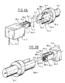
- FIGS. 2A and 2B describe the second embodiment of the device according to the invention.
- the side wall 20-2 of the second hollow part is split longitudinally into two identical parts, over a length of approximately 4 mm.
- the two edges of the slot thus formed form the two flats 202-2 and 203-2. These two flats are spaced 2.8 mm apart and the cylinder of revolution in which the external face 200-2 of the side wall is inscribed has a diameter of approximately 4 mm.
- the internal stud 22-2 is identical to that described in the previous embodiment.
- the side wall 10-2 of the first hollow part 1-2 comprises two side plates 102-2, 103-2, parallel to the flats 202-2 and 203-2, and spaced from each other by a distance about 2 mm.
- This side wall 10-2 also includes an upper plate 104-2 and a lower plate 105-2, the four plates of this side wall then forming a rectangular parallelepiped whose axis of symmetry is the interlocking axis 6-2 .
- Each side plate 102-2 and 103-2 has a rib extending transversely at its free end.
- the side wall 10-2 has four slots 13-2 formed over most of its length at the intersection of each of the four plates.
- the internal stud 12-2 is identical to the internal stud 12-1 in the first embodiment.
- the two upper and lower plates 104-2 and 105-2 are not really essential.
- the first hollow part only comprises the two side plates coming into contact with the two flats of the second hollow part.
- the nature of the dielectric as well as the geometric characteristics of the connection device are such that the electrical characteristics of the type of those mentioned above. front are substantially identical regardless of the position of the first hollow part relative to the second hollow part.
- the two parts can be coupled or uncoupled whatever their relative position.
- the device according to the invention also makes it possible, for example, to connect a two-wire shielded cable to a printed circuit board, that is to say a cable having an outer conductor surrounding two inner conductors.
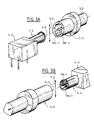
- a connection device is illustrated in FIGS. 3A and 3B.
- the side walls of the first and second hollow parts are identical to those described in the first embodiment.
- the second hollow part has inside its two identical internal studs 22a-3, 22b-3, parallel, cylindrical of revolution, and arranged symmetrically with respect to the interlocking axis 6-3.
- Each internal stud has a diameter of approximately 0.4 mm.
- the first hollow part 1-3 comprises two internal studs 12a-3,12b-3, identical, cylindrical, arranged symmetrically with respect to the interlocking axis and opposite the internal studs 22a-3 and 22b- 3.
- Each of these internal studs 12a-3 or 12b-3 has a structure similar to that described for the internal stud 12-1 of the first embodiment.
- Their outside diameter is however of the order of 0.8 mm.
- the two studs 22a-3 and 22b-3 fit into contact in the two studs 12a-3 and 12b-3, so as to ensure the electrical continuity of the two inner conductors of the shielded two-wire cable 3-3.
- the relative displacement can always be carried out along the axis of displacement 7-3.
- the number of internal studs inside the hollow parts is not limiting provided that their size is compatible with the geometric and electrical characteristics required for the connection device.
- the first hollow part has an additional side wall 10b-4 disposed substantially concentrically with the first side wall 10a-4 on the side of the external face of this latter wall, that is to say in the present case, surrounding it.
- the external diameter of the cylinder of revolution forming the external face of this additional wall 10b-4 is of the order of approximately 6.3 mm.
- the second hollow part also has a wall additional lateral 20b-4, disposed substantially concentrically with the lateral wall 20a-4, on the side of the external face of this latter wall, that is to say surrounding it.
- This additional side wall 20b-4 has on its internal face two additional flats 202b-4, 203b-4 respectively parallel to the two flats 202a-4 and 203a-4 of the side wall 20a-4.
- These two additional flats are spaced 6.3 mm apart and the cylinder of revolution forming the external face of the additional wall 20b-4 has a diameter of approximately 8.5 mm. .
- the dielectric separating the side wall 20a-4 from the side wall 20b-4 of the second hollow part is also air.
- the external face of the side wall 10b-4 of the first hollow part as well as the internal face of the side wall 20b-4 are shaped with a clearance jb-4 substantially parallel and at least equal to the clearance ja-4 separating the lateral wall 10a-4 of the side wall 20a-4.
- the external face of the side wall 10b-4 of the first hollow part also includes a connection zone not shown in FIG. 4 coming into contact on the two flats 202b-4 and 203b-4, which thus authorizes the relative displacement of the two hollow parts along an axis perpendicular to the interlocking axis.
- the invention is not limited to the embodiments below described above but embraces all variants, including the following: - It has been found to be particularly advantageous for the internal stud of the second hollow part to nest in the housing of the internal stud of the first hollow part; one could, however, have envisaged the reverse; - when the director of the cylinder in which the connection zone of the side wall of the first hollow part is inscribed is a polygon, the minimum condition required is that this polygon has two sides symmetrical with respect to the interlocking axis, these sides having to be substantially parallel to the two flats of the side wall of the second hollow part; - the dielectric used inside the connectors can be different from air as long as it allows to ensure the required electrical characteristics without preventing the relative displacement of the connectors; -
- the connection device according to the invention allows the relative movement of the two interlocked parts, in at least one direction perpendicular to the interlocking axis; - the specific application of the transport of microwave signals has been considered here.
- connection device could possibly be used for the connection of two conduits for transporting a fluid, which poses partly comparable problems. Adequate sealing means should then be provided. Those skilled in the art will also understand in this case that the complexity of the development of such a connection device is less than that encountered in particular in microwave, because the constraints of electrical characteristics which the connection device must satisfy then disappear.
Landscapes
- Coupling Device And Connection With Printed Circuit (AREA)
Applications Claiming Priority (2)
| Application Number | Priority Date | Filing Date | Title |
|---|---|---|---|
| FR8900055 | 1989-01-04 | ||
| FR8900055A FR2641419B1 (fr) | 1989-01-04 | 1989-01-04 | Dispositif de raccordement perfectionne, notamment pour signaux electromagnetiques hyperfrequences |
Publications (1)
| Publication Number | Publication Date |
|---|---|
| EP0378020A1 true EP0378020A1 (de) | 1990-07-18 |
Family
ID=9377471
Family Applications (1)
| Application Number | Title | Priority Date | Filing Date |
|---|---|---|---|
| EP89403517A Withdrawn EP0378020A1 (de) | 1989-01-04 | 1989-12-15 | Verbindungselement, insbesondere für hyperfrequente elektromagnetische Signale |
Country Status (3)
| Country | Link |
|---|---|
| US (1) | US5044989A (de) |
| EP (1) | EP0378020A1 (de) |
| FR (1) | FR2641419B1 (de) |
Cited By (1)
| Publication number | Priority date | Publication date | Assignee | Title |
|---|---|---|---|---|
| US5378958A (en) * | 1992-03-06 | 1995-01-03 | U.S. Philips Corporation | Capped electric lamp and connector for this lamp |
Families Citing this family (1)
| Publication number | Priority date | Publication date | Assignee | Title |
|---|---|---|---|---|
| US5440282A (en) * | 1994-03-03 | 1995-08-08 | Eagle Comtronics, Inc. | Filter structure with anti-rotation keying |
Citations (4)
| Publication number | Priority date | Publication date | Assignee | Title |
|---|---|---|---|---|
| FR1024147A (fr) * | 1949-09-01 | 1953-03-27 | Rollei Werke Franke Heidecke | Prise de courant notamment pour appareils photographiques |
| DE1959172U (de) * | 1966-12-10 | 1967-04-27 | Fuba Antennenwerke Hans Kolbe | Steckverbindung fuer koaxialkabel. |
| FR1534197A (fr) * | 1967-08-10 | 1968-07-26 | Amphenol Corp | Connecteur électrique |
| WO1983002690A1 (fr) * | 1982-01-28 | 1983-08-04 | Jean Bernard Roggeman | Connecteur electrique plat a trois broches |
Family Cites Families (2)
| Publication number | Priority date | Publication date | Assignee | Title |
|---|---|---|---|---|
| US2557130A (en) * | 1945-07-04 | 1951-06-19 | Mcgee Kenneth | Socket member for coaxial connectors |
| US3893743A (en) * | 1974-01-30 | 1975-07-08 | Perfection Enterprises Inc | Solid shell phonoconnectors |
-
1989
- 1989-01-04 FR FR8900055A patent/FR2641419B1/fr not_active Expired - Fee Related
- 1989-12-15 EP EP89403517A patent/EP0378020A1/de not_active Withdrawn
-
1990
- 1990-06-29 US US07/545,608 patent/US5044989A/en not_active Expired - Fee Related
Patent Citations (4)
| Publication number | Priority date | Publication date | Assignee | Title |
|---|---|---|---|---|
| FR1024147A (fr) * | 1949-09-01 | 1953-03-27 | Rollei Werke Franke Heidecke | Prise de courant notamment pour appareils photographiques |
| DE1959172U (de) * | 1966-12-10 | 1967-04-27 | Fuba Antennenwerke Hans Kolbe | Steckverbindung fuer koaxialkabel. |
| FR1534197A (fr) * | 1967-08-10 | 1968-07-26 | Amphenol Corp | Connecteur électrique |
| WO1983002690A1 (fr) * | 1982-01-28 | 1983-08-04 | Jean Bernard Roggeman | Connecteur electrique plat a trois broches |
Cited By (1)
| Publication number | Priority date | Publication date | Assignee | Title |
|---|---|---|---|---|
| US5378958A (en) * | 1992-03-06 | 1995-01-03 | U.S. Philips Corporation | Capped electric lamp and connector for this lamp |
Also Published As
| Publication number | Publication date |
|---|---|
| FR2641419B1 (fr) | 1991-03-29 |
| US5044989A (en) | 1991-09-03 |
| FR2641419A1 (fr) | 1990-07-06 |
Similar Documents
| Publication | Publication Date | Title |
|---|---|---|
| EP0064313B1 (de) | Mikrowellenstrahlerelement für Zirkularpolarisation und ebene Mikrowellenantenne mit einer Gruppe solcher Elemente | |
| FR2814598A1 (fr) | Connecteur muni de contacts montes dans un isolant adapte | |
| EP0613215B1 (de) | Koaxialer Winkelverbinder, bestimmt für Leiterplattenmontage | |
| FR2642232A1 (fr) | Interface de connexion ultra miniature pour haute frequence | |
| EP0305247B1 (de) | Verbindungsvorrichtung zweier koaxialer Mikrowellenstrukturen mit verschiedenen Durchmessern | |
| EP2572406B1 (de) | Antennenschnittstelle für einen funkempfänger | |
| FR2583227A1 (fr) | Unite de connexion universelle | |
| FR2778500A1 (fr) | Antenne a plaque | |
| EP0519812A1 (de) | Koaxialverbinder zum Verbinden eines Koaxialkabels mit einer elektronischen gedruckten Schaltung | |
| EP0708503B1 (de) | Elektrischer Verbinder mit mehreren Leitern ohne elektromagnetische Abschirmung zwischen den Leitern | |
| FR2606938A1 (fr) | Systeme de connecteurs electriques a haute densite | |
| EP0401121B1 (de) | Verbindungszusammenbau für gedruckte Schaltungskarten | |
| FR2693042A1 (fr) | Ensemble de connexion à fiche et embase et en particulier destiné à l'avionique. | |
| FR2643749A1 (fr) | Dispositif de couplage d'une ligne coaxiale a haute frequence | |
| EP1250731B1 (de) | Koaxial-steckverbinder und anordnung mit einem solchen verbinder | |
| EP3047535B1 (de) | Vorrichtung zur verbindung zwischen einer gedruckten übertragungsleitung und einem dielektrischen wellenleiter | |
| FR2641419A1 (fr) | Dispositif de raccordement perfectionne, notamment pour signaux electromagnetiques hyperfrequences | |
| EP1024546A1 (de) | Mikrowellenschaltkreismodul und Vorrichtung zum Verbinden mit einem weiteren Modul | |
| EP1152483A1 (de) | Zweiband-Mikrowellenstrahlelement | |
| FR2778752A1 (fr) | Connecteur optique | |
| EP0041877B1 (de) | Mikrowellen-Hohlleiterkoppler | |
| FR2585193A1 (fr) | Perfectionnements apportes a la construction d'une fiche pour cable coaxial d'antennes pour autoradios | |
| EP0693800A1 (de) | Hochfrequenzverbinder mit zusätzlicher Schaltfunktion | |
| WO2023214139A1 (fr) | Ensemble de connexion d'au moins une piste d'un circuit imprimé à un guide d'ondes en plastique | |
| EP3240119B1 (de) | Verbinder mit hebel und gedruckte schaltkreiskarte, die mit solchen verbindern ausgestattet ist |
Legal Events
| Date | Code | Title | Description |
|---|---|---|---|
| PUAI | Public reference made under article 153(3) epc to a published international application that has entered the european phase |
Free format text: ORIGINAL CODE: 0009012 |
|
| AK | Designated contracting states |
Kind code of ref document: A1 Designated state(s): CH DE GB IT LI |
|
| 17P | Request for examination filed |
Effective date: 19901004 |
|
| 17Q | First examination report despatched |
Effective date: 19930917 |
|
| STAA | Information on the status of an ep patent application or granted ep patent |
Free format text: STATUS: THE APPLICATION IS DEEMED TO BE WITHDRAWN |
|
| 18D | Application deemed to be withdrawn |
Effective date: 19940222 |