EP0378043A1 - Procédé et appareil pour charger un accumulateur - Google Patents
Procédé et appareil pour charger un accumulateur Download PDFInfo
- Publication number
- EP0378043A1 EP0378043A1 EP89810011A EP89810011A EP0378043A1 EP 0378043 A1 EP0378043 A1 EP 0378043A1 EP 89810011 A EP89810011 A EP 89810011A EP 89810011 A EP89810011 A EP 89810011A EP 0378043 A1 EP0378043 A1 EP 0378043A1
- Authority
- EP
- European Patent Office
- Prior art keywords
- accumulator
- voltage
- charging
- battery
- current
- Prior art date
- Legal status (The legal status is an assumption and is not a legal conclusion. Google has not performed a legal analysis and makes no representation as to the accuracy of the status listed.)
- Withdrawn
Links
Images
Classifications
-
- H—ELECTRICITY
- H02—GENERATION; CONVERSION OR DISTRIBUTION OF ELECTRIC POWER
- H02J—ELECTRIC POWER NETWORKS; CIRCUIT ARRANGEMENTS OR SYSTEMS FOR SUPPLYING OR DISTRIBUTING ELECTRIC POWER; SYSTEMS FOR STORING ELECTRIC ENERGY
- H02J7/00—Circuit arrangements for charging or discharging batteries or for supplying loads from batteries
- H02J7/90—Regulation of charging or discharging current or voltage
- H02J7/927—Regulation of charging or discharging current or voltage with introduction of pulses during the charging process
Definitions
- the present invention relates to a method for charging a rechargeable battery according to the preamble of claim 1.
- a method for charging a rechargeable battery is known from EP-A-0 198 990.
- the temperature of the rechargeable battery is detected as accurately as possible, and it is generates a reference voltage as a function of the measured temperature, and the charging of the rechargeable battery is ended when the reference voltage is no longer undershot during the pulsed discharge of the rechargeable battery.
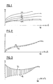
- the reason for this measure is that the accumulator voltage for a certain charge of the same strongly depends on the temperature. This dependency is shown in FIG. 1, which shows a family of charging curves for different temperatures.
- the voltage U of the battery for a certain state of charge depends strongly on the temperature
- rapid charging of the battery without the risk of overcharging or incomplete charging is only considered possible if the temperature of the battery, which rises during a fast charging process, is taken into account becomes.
- the temperature can only be taken into account if either a thermal sensor is built into the battery or if a suitable thermal sensor is brought into close enough contact with the battery to be charged.
- this poses certain problems particularly when it is necessary to charge batteries of various external shapes and sizes. It then becomes difficult to correctly attach both the connections for charging the accumulator and the thermal sensor for registering the temperature.
- the aim of the present invention is therefore to enable a battery to be charged correctly and quickly without taking the battery temperature into account.
- Each a solution is specified in the characterizing part of claims 1 and 6. It can be seen that the discharge voltage of the rechargeable battery during the pulsed discharge process has a value that increases continuously during the charging process until it is fully charged. When the full charge is exceeded, however, this voltage drops. This phenomenon is explained by the fact that after the accumulator has been charged, the energy supplied is converted fully into heat and the accumulator is rapidly heated, so that its voltage now drops as a result of the temperature dependence of the accumulator voltage illustrated in FIG. 1. If, according to the invention, the periodically recorded discharge voltage is compared with the discharge voltage determined in the previous measurement process, it can be determined when the difference between these voltages becomes negative, and at this moment the full charge is reached and the charging process is interrupted.
- the invention also relates to a charger, in particular for carrying out the method described above, according to claim 7. Accordingly, the device is preferably controlled by a processor, which results in very flexible control of the charging processes and a versatile setting and display option.
- the essential relationship between the voltage of an accumulator, in particular Ni-Cd or Ni-Fe accumulator, and its state of charge is shown above. It can be seen that the battery voltage is much higher for low temperatures than for high temperatures. However, the battery voltage rises steadily regardless of the temperature with increasing charge up to a maximum, above which it then drops relatively quickly.
- FIG. 2 shows a corresponding charging curve for a rechargeable battery, where U L indicates the respective charging voltage during the rapid charging process and U E the corresponding course of the discharging voltage, ie the voltage during the strong discharge of the rechargeable battery. It can be seen from FIG. 2 that with a good accumulator the difference between U L and U E is relatively small.
- FIG. 3 shows the corresponding curves for a strongly discharged accumulator without an initial capacity. Initially, ie with a low charge, the difference between the charging voltage U L and the discharging voltage U E is considerable, while with a full charge it is similar to that of a good one according to FIG Accumulator.
- the accumulator is charged intermittently, ie it is charged with a specific current of, for example, 0.1 to 2.5 A per Ah accumulator capacity for a specific duration of, for example, 20-70 seconds after this charging phase has elapsed, a short discharge phase is initiated during which the battery is discharged for about 10 to 2000 milliseconds with a current of 0.1 to 2.5 A per Ah of battery capacity.
- the short discharge phases are indicated in FIGS. 2 and 3 by vertical lines which at the same time illustrate the voltage difference between the charging voltage and the discharging voltage.
- the respective short discharge with a relatively high current not only has the advantage of avoiding the so-called memory effect, ie blockage of the fine openings of the sintered electrode and thus loss of capacity, but the discharge voltage is preferably used as a reference voltage, ie the periodic detection of reference values synchronized with the respective unloading process.
- a reference voltage ie the periodic detection of reference values synchronized with the respective unloading process.
- a rapid charge can be followed by a recharging with a lower current of, for example, 0.01 to 0.9 A per Ah battery capacity, either immediately or with a certain delay.
- This recharging takes place in the same rhythm, ie with charging periods of, for example, 20-70 seconds and discharging periods of 10 ms to 2 seconds. In this case, the battery cools down and a full charge corresponding to the cooled battery can be achieved.
- This recharging can also be terminated in the same sense as described above, ie if the charging voltage U L or preferably the discharging voltage U E of the accumulator no longer rises or falls, the recharging process is terminated.
- a current of 1/30 to 1/20 A per Ah battery capacity can then be supplied in order to maintain the battery charge (self-discharge).
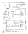
- FIG. 4 shows the essential circuit parts of the charging device according to the invention, various connections being omitted, in particular within the processor, for reasons of space and to maintain clarity.
- the rechargeable battery 1 is between Charging terminals 2 and 3 connected. A charging current is fed to it via an output amplifier 4.
- the power amplifier 4 is preceded by a preamplifier 5, which can be controlled via a switch 6.
- the accumulator voltage at terminal 2 is fed to an analog-digital converter 8 of processor 9 via a voltage divider 7.
- the accumulator 1 can be discharged via a power amplifier 10.
- the power amplifier 10 is controlled by a switch 11.
- the switches 6 and 11 are controlled by the processor 9.
- the circuit has two selector switches 12 and 13.
- Each of these switches can be used to switch one of several graduated resistors into the circuit of a current source 14 or 15.
- the voltage drop across the switched-on resistor is fed to an analog-digital converter 16 or 17, which converts the set voltage drop into digital information.
- This digital information is fed to a converter 18 or 19, which converts the applied voltage value into a control voltage.
- This control voltage which is in digital form, is optionally supplied via circuits 20 or 21 to a digital-to-analog converter 22, which optionally controls the amplifier 4 or 10 via one of the switches 6 or 11.
- the analog-digital converter 8 is optionally connected via a circuit 23 to two changeable memories 24 and 25, in which the digital output value of the analog-digital converter 8 can optionally be stored.
- the outputs of the memories 24 and 25 are connected to a comparison circuit 26 which determines the difference between the output values of the memories 24 and 25 and which generates an output signal when the difference between two successive stored values becomes negative.
- the battery 1 to be charged is inserted and connected to the connection terminals 2 and 3.
- the assigned setting is selected by means of the selector switch 12 in accordance with the number of cells or the total nominal voltage of the accumulator. In this way, a short circuit or interruption of an individual cell can be detected, for example.
- the capacity of the battery is adjusted accordingly, and the analog-to-digital converter 17 and the converter 19 thus control the amplifier 4, 5 with such an analog voltage that the battery is charged with the correct current and via the Analog-to-digital converter 16 and the converter 18, as well as the digital-to-analog converter 22 and the switch 11, an analog control voltage is fed to the amplifier 10, which controls this amplifier in such a way that in each case a discharge current is extracted from the accumulator, which is in a certain ratio to the accumulator capacity .
- the switches 6 and 11 are now controlled by the microprocessor 9 such that, according to the above, the accumulator is charged via the amplifier 4 for, for example, 70 seconds, after which it is discharged via the amplifier 10 for 10 ms to 2 seconds.
- the control takes place in such a way that, during this short discharge phase of 10 ms to 2 seconds, the discharge voltage at the accumulator is recorded via the digital-analog converter 8 and is alternately stored in one of the memories 24 and 25.
- the voltage values stored in this way increase continuously during the normal charging of the battery. If the accumulator is fully charged, however, these voltage values begin to drop, and as soon as a first drop is determined by the comparison circuit 26, the rapid charging process is switched off.
- a reload process can then be initiated be, during which is charged with a reduced current, while the full discharge current is withdrawn in pulses. This recharging begins with a certain delay, which is set by the processor in order to let the accumulator cool down. This process is interrupted after a certain time.
- the microprocessor can then control the supply of a trickle charge current to the accumulator for an indefinite period of time until it is removed from the device, with charging and discharging also being carried out cyclically.
- the device can furthermore have means for determining defective accumulators which, for example, have a cell closure.
- the total nominal voltage of the accumulator or the number of cells thereof is set by means of the selector switch 12. If the set nominal voltage of the accumulator is not reached even when the accumulator is fully charged, ie when the determined discharge voltages begin to decrease, this is a sign that the accumulator is defective. This fact can be indicated by means of a certain light display.
- a further comparison circuit 27 can be provided, which compares the digitized reference voltage with the digitized measured voltage U L or U E.
- there may be further light indicators which indicate certain operating states of the device, for example normal charging, recharging, supplying a trickle charge current or readiness of the charger, or already charged capacity in%.
- the analog values of the discharge voltage could be stored continuously and it could be determined when the stored value begins to decrease in order to switch off the charging process in each case.
- the amplifier 4 works in the case of a small battery voltage, relatively uneconomical, since a considerable voltage drop must be generated in the power transistor. It is therefore possible to provide a switchable voltage source for different charging voltages. It is also possible to control the amplifier 4 with pulses of relatively high frequency and variable width and to smooth the pulsating current. Although it is advantageous to record the accumulator voltage U E as the reference voltage during the discharge pulse, but as the curves in FIGS.
- these reference values could be entered and stored directly in digital form using buttons or corresponding selector switches.
- the processor permits displays of the state of charge of the accumulator, the discharge voltage U E detected in each case being compared with reference voltages present in memories.
- a partial aim of the invention is to charge the accumulator correctly and gently without detecting its temperature. If you do this on a quick charge is not instructed, it is possible to get by without detecting the battery voltage. This is possible if a charge current of at most IC 1/10, ie at most 1/10 A per 1 Ah capacity, is charged for an arbitrarily long period of time and a discharge current pulse is also periodically withdrawn. In this case, charging can preferably take about 20 seconds each and discharge during 50 ms.
- accumulators can remain connected as long as they want without being damaged. It was found that with this charging method, an accumulator still had a capacity of 90% after 2000 charging / discharging cycles, whereas a lifespan of 300 cycles is stated for known charging methods.
Landscapes
- Engineering & Computer Science (AREA)
- Power Engineering (AREA)
- Charge And Discharge Circuits For Batteries Or The Like (AREA)
Priority Applications (1)
| Application Number | Priority Date | Filing Date | Title |
|---|---|---|---|
| EP89810011A EP0378043A1 (fr) | 1989-01-09 | 1989-01-09 | Procédé et appareil pour charger un accumulateur |
Applications Claiming Priority (1)
| Application Number | Priority Date | Filing Date | Title |
|---|---|---|---|
| EP89810011A EP0378043A1 (fr) | 1989-01-09 | 1989-01-09 | Procédé et appareil pour charger un accumulateur |
Publications (1)
| Publication Number | Publication Date |
|---|---|
| EP0378043A1 true EP0378043A1 (fr) | 1990-07-18 |
Family
ID=8203125
Family Applications (1)
| Application Number | Title | Priority Date | Filing Date |
|---|---|---|---|
| EP89810011A Withdrawn EP0378043A1 (fr) | 1989-01-09 | 1989-01-09 | Procédé et appareil pour charger un accumulateur |
Country Status (1)
| Country | Link |
|---|---|
| EP (1) | EP0378043A1 (fr) |
Cited By (1)
| Publication number | Priority date | Publication date | Assignee | Title |
|---|---|---|---|---|
| EP0981194A3 (fr) * | 1998-07-31 | 2001-05-09 | Canon Kabushiki Kaisha | Procédé et dispositif pour le chargement d'une batterie secondaire |
Citations (6)
| Publication number | Priority date | Publication date | Assignee | Title |
|---|---|---|---|---|
| DE2940011A1 (de) * | 1979-10-03 | 1981-04-09 | Institut für Rundfunktechnik GmbH, 8000 München | Verfahren zum schnelladen eines akkumulators |
| DE2948251A1 (de) * | 1979-11-30 | 1981-06-04 | Neuhierl, Hermann, Dipl.-Chem. Dr., 8510 Fürth | Ladegeraet fuer nc-zellen |
| EP0034003A1 (fr) * | 1980-01-11 | 1981-08-19 | Rediffusion Radio Systems Limited | Chargeur de batterie |
| DE3040852A1 (de) * | 1980-10-30 | 1982-06-03 | Licentia Patent-Verwaltungs-Gmbh, 6000 Frankfurt | Ladeschaltung fuer batterien, insbesondere nicd-batterien |
| EP0147241A2 (fr) * | 1983-12-30 | 1985-07-03 | Alexander Manufacturing Company | Procédé et appareil pour charger une batterie Nickel-Cadmium |
| EP0181112A2 (fr) * | 1984-10-29 | 1986-05-14 | Christie Electric Corp. | Dispositif de commande pour un chargeur de batterie |
-
1989
- 1989-01-09 EP EP89810011A patent/EP0378043A1/fr not_active Withdrawn
Patent Citations (6)
| Publication number | Priority date | Publication date | Assignee | Title |
|---|---|---|---|---|
| DE2940011A1 (de) * | 1979-10-03 | 1981-04-09 | Institut für Rundfunktechnik GmbH, 8000 München | Verfahren zum schnelladen eines akkumulators |
| DE2948251A1 (de) * | 1979-11-30 | 1981-06-04 | Neuhierl, Hermann, Dipl.-Chem. Dr., 8510 Fürth | Ladegeraet fuer nc-zellen |
| EP0034003A1 (fr) * | 1980-01-11 | 1981-08-19 | Rediffusion Radio Systems Limited | Chargeur de batterie |
| DE3040852A1 (de) * | 1980-10-30 | 1982-06-03 | Licentia Patent-Verwaltungs-Gmbh, 6000 Frankfurt | Ladeschaltung fuer batterien, insbesondere nicd-batterien |
| EP0147241A2 (fr) * | 1983-12-30 | 1985-07-03 | Alexander Manufacturing Company | Procédé et appareil pour charger une batterie Nickel-Cadmium |
| EP0181112A2 (fr) * | 1984-10-29 | 1986-05-14 | Christie Electric Corp. | Dispositif de commande pour un chargeur de batterie |
Cited By (2)
| Publication number | Priority date | Publication date | Assignee | Title |
|---|---|---|---|---|
| EP0981194A3 (fr) * | 1998-07-31 | 2001-05-09 | Canon Kabushiki Kaisha | Procédé et dispositif pour le chargement d'une batterie secondaire |
| US6377030B1 (en) | 1998-07-31 | 2002-04-23 | Canon Kabushiki Kaisha | Method of charging secondary battery by varying current or voltage at an inflection point in a storage region before full charge and device therefor |
Similar Documents
| Publication | Publication Date | Title |
|---|---|---|
| DE69718453T2 (de) | Verfahren und vorrichtung zur batterieladung | |
| AT406719B (de) | Verfahren zum vorzugsweisen schnellen laden von batterien | |
| DE69233127T2 (de) | Verfahren zum Laden einer Wiederaufladbaren Batterie | |
| DE69409863T2 (de) | Batterieladegerät | |
| DE69321490T2 (de) | Wiederaufladbare Batterie und Batterieladesystem | |
| CA2128507C (fr) | Methode et appareil de chargement rapide de batterie | |
| DE69736730T2 (de) | Ladegerät | |
| DE69112243T2 (de) | Batterieladegerät. | |
| DE69011462T2 (de) | Anordnung zum Laden einer Batterie. | |
| EP0584362B1 (fr) | Procede de charge d'accumulateurs et appareil associe | |
| DE4200693C1 (fr) | ||
| DE69625714T2 (de) | Digital gesteuertes schaltnetzteil zum laden von wiederaufladbaren batterien | |
| DE112017005341T5 (de) | Verfahren zum schnellladen von lithium-ionen-akkumulatoren | |
| EP1391742B1 (fr) | Dispositif de surveillance et procédé de détermination de l'état de fonctionnement d'une batterie d'accumulateurs | |
| DE102011087496A1 (de) | Verfahren und Vorrichtung zum Laden von wiederaufladbaren Zellen | |
| DE69329479T2 (de) | Batterieladegerät | |
| DE19527787B4 (de) | Verfahren und Vorrichtung zum Laden einer Sekundärbatterie | |
| DE69419362T2 (de) | Batterieladegerät | |
| DE19520619A1 (de) | Batterieladegerät mit Überwachung der Batteriespannung und/oder der Temperatur in relevanten Abtastintervallen | |
| DE60205306T2 (de) | Verfahren und Vorrichtung zur Batterieladung | |
| DE3526045C2 (de) | Verfahren zum Laden von NC-Akkumulatoren und Ladegerät zur Durchführung des Verfahrens | |
| EP0114871B1 (fr) | Procede et dispositif pour le controle de la capacite a chaque fois chargee d'accumulateurs | |
| DE19853631C2 (de) | Batterieladegerät mit Fehlerdetektion | |
| JP3291405B2 (ja) | 電池の充電方法 | |
| EP0378043A1 (fr) | Procédé et appareil pour charger un accumulateur |
Legal Events
| Date | Code | Title | Description |
|---|---|---|---|
| PUAI | Public reference made under article 153(3) epc to a published international application that has entered the european phase |
Free format text: ORIGINAL CODE: 0009012 |
|
| AK | Designated contracting states |
Kind code of ref document: A1 Designated state(s): AT BE CH DE ES FR GB GR IT LI LU NL SE |
|
| RBV | Designated contracting states (corrected) |
Designated state(s): AT BE CH DE FR GB IT LI LU NL SE |
|
| STAA | Information on the status of an ep patent application or granted ep patent |
Free format text: STATUS: THE APPLICATION IS DEEMED TO BE WITHDRAWN |
|
| 18D | Application deemed to be withdrawn |
Effective date: 19910119 |