EP0378570B1 - A device for measuring the volume flow of a fan - Google Patents
A device for measuring the volume flow of a fan Download PDFInfo
- Publication number
- EP0378570B1 EP0378570B1 EP88908231A EP88908231A EP0378570B1 EP 0378570 B1 EP0378570 B1 EP 0378570B1 EP 88908231 A EP88908231 A EP 88908231A EP 88908231 A EP88908231 A EP 88908231A EP 0378570 B1 EP0378570 B1 EP 0378570B1
- Authority
- EP
- European Patent Office
- Prior art keywords
- measuring
- flow
- pressure
- measuring part
- fan
- Prior art date
- Legal status (The legal status is an assumption and is not a legal conclusion. Google has not performed a legal analysis and makes no representation as to the accuracy of the status listed.)
- Expired - Lifetime
Links
- 238000004378 air conditioning Methods 0.000 description 8
- 238000000034 method Methods 0.000 description 6
- 230000007123 defense Effects 0.000 description 2
- 238000005192 partition Methods 0.000 description 2
- 238000010276 construction Methods 0.000 description 1
- 230000000694 effects Effects 0.000 description 1
- 238000005259 measurement Methods 0.000 description 1
- 230000001105 regulatory effect Effects 0.000 description 1
Images
Classifications
-
- G—PHYSICS
- G01—MEASURING; TESTING
- G01F—MEASURING VOLUME, VOLUME FLOW, MASS FLOW OR LIQUID LEVEL; METERING BY VOLUME
- G01F1/00—Measuring the volume flow or mass flow of fluid or fluent solid material wherein the fluid passes through a meter in a continuous flow
- G01F1/05—Measuring the volume flow or mass flow of fluid or fluent solid material wherein the fluid passes through a meter in a continuous flow by using mechanical effects
- G01F1/34—Measuring the volume flow or mass flow of fluid or fluent solid material wherein the fluid passes through a meter in a continuous flow by using mechanical effects by measuring pressure or differential pressure
- G01F1/36—Measuring the volume flow or mass flow of fluid or fluent solid material wherein the fluid passes through a meter in a continuous flow by using mechanical effects by measuring pressure or differential pressure the pressure or differential pressure being created by the use of flow constriction
- G01F1/40—Details of construction of the flow constriction devices
- G01F1/46—Pitot tubes
-
- F—MECHANICAL ENGINEERING; LIGHTING; HEATING; WEAPONS; BLASTING
- F04—POSITIVE - DISPLACEMENT MACHINES FOR LIQUIDS; PUMPS FOR LIQUIDS OR ELASTIC FLUIDS
- F04D—NON-POSITIVE-DISPLACEMENT PUMPS
- F04D27/00—Control, e.g. regulation, of pumps, pumping installations or pumping systems specially adapted for elastic fluids
- F04D27/001—Testing thereof; Determination or simulation of flow characteristics; Stall or surge detection, e.g. condition monitoring
-
- F—MECHANICAL ENGINEERING; LIGHTING; HEATING; WEAPONS; BLASTING
- F24—HEATING; RANGES; VENTILATING
- F24F—AIR-CONDITIONING; AIR-HUMIDIFICATION; VENTILATION; USE OF AIR CURRENTS FOR SCREENING
- F24F11/00—Control or safety arrangements
- F24F11/70—Control systems characterised by their outputs; Constructional details thereof
- F24F11/72—Control systems characterised by their outputs; Constructional details thereof for controlling the supply of treated air, e.g. its pressure
-
- G—PHYSICS
- G01—MEASURING; TESTING
- G01F—MEASURING VOLUME, VOLUME FLOW, MASS FLOW OR LIQUID LEVEL; METERING BY VOLUME
- G01F1/00—Measuring the volume flow or mass flow of fluid or fluent solid material wherein the fluid passes through a meter in a continuous flow
- G01F1/05—Measuring the volume flow or mass flow of fluid or fluent solid material wherein the fluid passes through a meter in a continuous flow by using mechanical effects
- G01F1/34—Measuring the volume flow or mass flow of fluid or fluent solid material wherein the fluid passes through a meter in a continuous flow by using mechanical effects by measuring pressure or differential pressure
- G01F1/36—Measuring the volume flow or mass flow of fluid or fluent solid material wherein the fluid passes through a meter in a continuous flow by using mechanical effects by measuring pressure or differential pressure the pressure or differential pressure being created by the use of flow constriction
Definitions
- the invention relates to a measuring device for measuring the volume flow rate of a fan in an air-conditioning plant or in some other air-treatment system.
- the air volume flow rate in an air-conditioning plant is generally measured according to the multi-point methods presented in Directive 2:1984 issued by the Finnish National Board of Public Construction.
- the volume flow of air is obtained as the product of the mean air velocity and the cross-sectional area of the flow in the duct.
- the mean velocity of the air is determined by measuring the air velocity at mathematically predetermined points of the cross section of the duct and by calculating the mean of these velocities. Depending on the size of the duct, the measuring points number 5 - 24.
- Another method for measuring the air volume flow rate in an air-conditioning plant is to measure in a measuring device fixedly installed in the duct system the pressure difference proportional to the air volume flow rate.
- throttling means which may be, for example, a throttling flange, a nozzle, a venturi tube, a Dall tube or a segment flange, for producing the pressure difference.
- the method for determining the volume flow rate of a fan in an air-conditioning plant is based on the measuring of the total pressure and rotative velocity of the fan and the electric power taken by the fan motor.
- the volume flow of the fan is obtained with the aid of these from the characteristic curve charts prepared by the fan manufacturer.
- Another method for determining the volume flow rate of a fan is in use in the fans used in civil defense shelters in Finland.
- a by-pass via a rotameter is obtained by using airflow throttling means located in the pressure aperture of the fan.
- the rotameter is calibrated to indicate the air volume flow rate of the fan.
- the multi-point system for volume-flow rate determination is cumbersome. In practice it is also susceptible to errors, since complicated air-conditioning ducts seldom have a disturbance-free flow profile required by reliable measuring.
- the permanent pressure loss caused by measuring devices fixedly installed in a duct system is usually significant, and the lower limit of the measuring range is limited to correspond to relatively high volume flow rates.
- the method for determining the volume flow rate in a fan with the aid of a characteristic curve chart of the fan is very approximate.
- the throttling means used in fans in civil defense shelters causes a permanent pressure loss. Owing to its tendency to become soiled, a rotameter for its part is not suitable for use on a continual basis in conventional air-conditioning plants.
- Measuring devices for measuring the volume flow of a fan are also known from US-A-3 759 098 and US-A-3 751 982.
- the device according to the invention is characterized in what is disclosed in Claim 1.
- the total air volume flow rate in an air-conditioning plant can be obtained easily and reliably with one measurement and one measuring tool. It is a further advantage that the volume flow rate is obtained as a continuous value, in which case, for example, disturbances are visible immediately and the control of the plant is effective, since the feedback time constant is low.
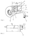
- Figure 1 depicts a measuring device according to the invention, installed in a fan.
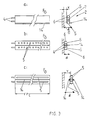
- Figure 2 depicts one embodiment of the measuring part of the measuring device according to the invention.
- Figure 3 depicts other embodiments of the measuring part of the measuring device according to the invention.
- the measuring device comprises the housing 1 of the device and a measuring part 2.
- the housing of the measuring device 1 is connected to the pressure aperture of the fan 3 in such a way that the inner surface 8 of the housing on the same side as the measuring part forms a continuation of the extended cut-off 9 of the fan in the flow direction F.
- the pressure difference measured in the measuring part 2, which is located immediately adjacent to the inner surface 8 of the housing 1, or close to the inner surface 8, and transversely to the flow F and which extends over its length c substantially across the whole housing from its one side 11 to its other side 11, is proportional to the volume flow of the fan.
- the length c of the measuring part 2, transverse to the housing is perpendicular to the flow direction F.
- the housing 1 of the device is a tubular sleeve which has the size and shape of the pressure aperture of the fan and does not throttle the flow.
- the measuring part 2 can be located even further away from the inner surface 8 on the same side as the extended cut-off in the cross section of the housing 1.
- Figure 1 also depicts the flow field in the pressure aperture of the fan and in its vicinity, when the flow is strongly throttled by non-depicted means, for example by using control dampers, in some other part of the pipe system.
- the measuring part remains in an even pressure field in spite of the turbulence caused by the throttling. If the throttling is less vigorous, the flow field is more even uniform, i.e. less turbulent.
- the length of the housing 1 of the measuring device in the direction of the flow must be such that the distance E of the measuring part from the trailing edge 12 of the housing is at minimum 0.3 x b, to avoid the turbulence, etc., caused by the trailing edge or other similar discontinuity point, and to maintain reliability.
- Figure 2 depicts the measuring part 2 of the measuring device.
- the pressure caused by the gas flow F is transmitted via the pressure-measuring apertures 5 and chambers 6 to the pressure-measuring tubes 4 and further to the differential pressure gauge 13.
- a partition 7 separates the pressure-measuring chambers 6 from one another.
- the differential pressure gauge 13 may be structurally of any known suitable type.
- the measuring part of the type depicted in Figure 2 is suitable for use in such a way that the straight or somewhat curved surface between the pressure-measuring apertures 5 is either pressed tightly against the inner surface 8 of the housing or is at a small distance x from the inner surface 8 of the housing.
- Figures 3a and 3b depict certain other embodiments of the measuring part 2 of the measuring device; these embodiments are suitable for being positioned either tightly against the inner surface 8 or at a small distance x from the inner surface 8.
- Figure 3c further depicts one embodiment of the measuring part 2 which is suitable for being located at a small distance y from the surface 8. All these embodiments have pressure-measuring apertures 5 and chambers 6, pressure-measuring tubes 4 and partitions 7.
- each of the measuring parts in Figure 3 has an external protrusion 14 to increase the pressure difference.
- the protrusion 14, as well as the entire measuring part 2 is dimensionally as small as possible compared with the cross sectional dimension b of the housing 1 and at the same time of the pressure aperture of the fan, in order to avoid a throttling effect in the flow.
- the measuring part 2 of the measuring device can, depending on its design, be installed inside the housing 1 also so as to turn about its longitudinal axis, and especially so if the measuring part 2 is designed to be of a blade structure type in order to produce a pressure difference.
Landscapes
- Engineering & Computer Science (AREA)
- Fluid Mechanics (AREA)
- General Physics & Mathematics (AREA)
- Mechanical Engineering (AREA)
- General Engineering & Computer Science (AREA)
- Physics & Mathematics (AREA)
- Chemical & Material Sciences (AREA)
- Combustion & Propulsion (AREA)
- Measuring Volume Flow (AREA)
- Measuring Fluid Pressure (AREA)
- Control Of Positive-Displacement Air Blowers (AREA)
- External Artificial Organs (AREA)
- Ventilation (AREA)
- Organic Low-Molecular-Weight Compounds And Preparation Thereof (AREA)
- Other Investigation Or Analysis Of Materials By Electrical Means (AREA)
- Preparation Of Compounds By Using Micro-Organisms (AREA)
- Structures Of Non-Positive Displacement Pumps (AREA)
Applications Claiming Priority (3)
| Application Number | Priority Date | Filing Date | Title |
|---|---|---|---|
| FI874009A FI81447C (fi) | 1987-09-15 | 1987-09-15 | Anordning foer uppmaetning av volymstroem i blaester. |
| FI874009 | 1987-09-15 | ||
| PCT/FI1988/000149 WO1989002581A1 (en) | 1987-09-15 | 1988-09-14 | A device for measuring the volume flow of a fan |
Publications (2)
| Publication Number | Publication Date |
|---|---|
| EP0378570A1 EP0378570A1 (en) | 1990-07-25 |
| EP0378570B1 true EP0378570B1 (en) | 1996-05-22 |
Family
ID=8525063
Family Applications (1)
| Application Number | Title | Priority Date | Filing Date |
|---|---|---|---|
| EP88908231A Expired - Lifetime EP0378570B1 (en) | 1987-09-15 | 1988-09-14 | A device for measuring the volume flow of a fan |
Country Status (7)
| Country | Link |
|---|---|
| EP (1) | EP0378570B1 (da) |
| AT (1) | ATE138472T1 (da) |
| CA (1) | CA1332294C (da) |
| DE (1) | DE3855311T2 (da) |
| DK (1) | DK172363B1 (da) |
| FI (1) | FI81447C (da) |
| WO (1) | WO1989002581A1 (da) |
Cited By (2)
| Publication number | Priority date | Publication date | Assignee | Title |
|---|---|---|---|---|
| FR2785675A1 (fr) | 1998-11-09 | 2000-05-12 | Gauting Gmbh Apparatebau | Soufflante comprenant un dispositif pour la determination du debit massique ou volumique du fluide vehicule |
| WO2025003574A1 (en) * | 2023-06-28 | 2025-01-02 | Finnfort Safety Oy | A ventilation apparatus |
Families Citing this family (9)
| Publication number | Priority date | Publication date | Assignee | Title |
|---|---|---|---|---|
| DE8911433U1 (de) * | 1989-09-26 | 1989-11-23 | Gebhardt Ventilatoren GmbH & Co, 7112 Waldenburg | Vorrichtung zur Bestimmung des Volumenstroms eines Radialventilators |
| SE500539C2 (sv) * | 1991-06-12 | 1994-07-11 | Flaekt Ab | Sätt och anordning för bestämning av genomströmningsflödet i en ventilationsanläggning med en frisugande fläkt |
| DE19924400C1 (de) * | 1999-05-27 | 2001-01-25 | Securiton Ag | Brandmelder und Verfahren zur Branddetektion |
| ITMI20022365A1 (it) * | 2002-11-07 | 2004-05-08 | Riello Spa | Caldaia |
| DE10305049B4 (de) | 2003-02-07 | 2018-08-02 | Trützschler GmbH & Co Kommanditgesellschaft | Vorrichtung zum pneumatischen Speisen mindestens einer Spinnereivorbereitungsmaschine, z.B. Karde, Reiniger |
| DE10359726A1 (de) * | 2003-12-19 | 2005-07-14 | Ksb Aktiengesellschaft | Mengenmessung |
| US9528865B2 (en) | 2012-11-02 | 2016-12-27 | Johnson Controls Technology Company | Methods and systems for determining flow direction using a bidirectional pressure sensor |
| DE102016118369A1 (de) * | 2016-09-28 | 2018-03-29 | Ebm-Papst Mulfingen Gmbh & Co. Kg | Ansaugdüse und Ausblaseinheit eines Ventilators |
| CN106931599A (zh) * | 2017-03-17 | 2017-07-07 | 中国船舶重工集团公司第七〇四研究所 | 船用变风量末端风量测量装置及标定方法 |
Family Cites Families (9)
| Publication number | Priority date | Publication date | Assignee | Title |
|---|---|---|---|---|
| US1508017A (en) * | 1922-12-11 | 1924-09-09 | Frederick W Greve | Pitometer |
| US3701280A (en) * | 1970-03-18 | 1972-10-31 | Daniel Ind Inc | Method and apparatus for determining the supercompressibility factor of natural gas |
| US3751982A (en) * | 1971-05-03 | 1973-08-14 | R Lambert | Fluid flow meter head and system using same |
| US3733900A (en) * | 1971-11-22 | 1973-05-22 | Air Monitor Corp | Fan capacity measuring station |
| US3759098A (en) * | 1972-01-27 | 1973-09-18 | Aeronca Inc | Apparatus for determining fluid flow in a conduit |
| GB2043917B (en) * | 1979-01-25 | 1983-02-23 | Fincoil Teollisuus Oy | Apparatus for determining the differential pressure and rate in a conduit |
| US4559835A (en) * | 1983-08-11 | 1985-12-24 | Air Monitor Corporation | Flow measuring traverse probe |
| DE3343284C2 (de) * | 1983-11-30 | 1985-11-28 | Thomas Dipl.-Ing. 7500 Karlsruhe Carolus | Strömungsarbeitsmaschine |
| CA1246356A (en) * | 1986-05-26 | 1988-12-13 | Ernest Hajto | Fluid flow sensor having multiplying effect |
-
1987
- 1987-09-15 FI FI874009A patent/FI81447C/fi not_active IP Right Cessation
-
1988
- 1988-09-07 CA CA000576644A patent/CA1332294C/en not_active Expired - Fee Related
- 1988-09-14 EP EP88908231A patent/EP0378570B1/en not_active Expired - Lifetime
- 1988-09-14 AT AT88908231T patent/ATE138472T1/de not_active IP Right Cessation
- 1988-09-14 WO PCT/FI1988/000149 patent/WO1989002581A1/en not_active Ceased
- 1988-09-14 DE DE3855311T patent/DE3855311T2/de not_active Expired - Fee Related
-
1990
- 1990-03-15 DK DK067690A patent/DK172363B1/da not_active IP Right Cessation
Cited By (3)
| Publication number | Priority date | Publication date | Assignee | Title |
|---|---|---|---|---|
| FR2785675A1 (fr) | 1998-11-09 | 2000-05-12 | Gauting Gmbh Apparatebau | Soufflante comprenant un dispositif pour la determination du debit massique ou volumique du fluide vehicule |
| DE19851523C1 (de) * | 1998-11-09 | 2000-05-18 | Gauting Gmbh Apparatebau | Gebläse |
| WO2025003574A1 (en) * | 2023-06-28 | 2025-01-02 | Finnfort Safety Oy | A ventilation apparatus |
Also Published As
| Publication number | Publication date |
|---|---|
| DE3855311T2 (de) | 1996-12-19 |
| DK67690D0 (da) | 1990-03-15 |
| CA1332294C (en) | 1994-10-11 |
| ATE138472T1 (de) | 1996-06-15 |
| DE3855311D1 (de) | 1996-06-27 |
| FI81447B (fi) | 1990-06-29 |
| DK172363B1 (da) | 1998-04-14 |
| FI874009L (fi) | 1989-03-16 |
| FI81447C (fi) | 1990-10-10 |
| FI874009A0 (fi) | 1987-09-15 |
| DK67690A (da) | 1990-03-15 |
| WO1989002581A1 (en) | 1989-03-23 |
| EP0378570A1 (en) | 1990-07-25 |
Similar Documents
| Publication | Publication Date | Title |
|---|---|---|
| US4343194A (en) | Flow sensing apparatus | |
| EP0378570B1 (en) | A device for measuring the volume flow of a fan | |
| US4638672A (en) | Fluid flowmeter | |
| US5146941A (en) | High turndown mass flow control system for regulating gas flow to a variable pressure system | |
| US5295397A (en) | Slotted orifice flowmeter | |
| US5461932A (en) | Slotted orifice flowmeter | |
| US6487918B1 (en) | Airflow sensor for averaging total pressure | |
| US5406839A (en) | Incidence probe with multiple pressure inlets | |
| US3981193A (en) | Fluid pressure sensing apparatus | |
| US4372170A (en) | Flow measuring apparatus | |
| US4520844A (en) | Regulator valve for stabilizing volume flow, especially in ventilation systems | |
| US5379792A (en) | Damper with blade for sensing pressure differential | |
| JP3657354B2 (ja) | 動圧測定装置 | |
| US6149515A (en) | Combination moisture elimination louver and air flow sensor and method | |
| GB2246436A (en) | Fluid flowmeter | |
| US7228750B2 (en) | Apparatus and method for measuring fluid flow | |
| US4630484A (en) | Mass flowmeter | |
| US6923715B2 (en) | Device for regulating the air volume flow for a vent in a laboratory | |
| JP3607041B2 (ja) | 流量制御弁装置 | |
| WO1989003977A1 (en) | Method and arrangement for measuring gas flow parameters | |
| GB1574702A (en) | Fluid flow measuring assembly | |
| EP0205204B1 (en) | Apparatus for measuring a gas mass flowing per unit of time through a pipe | |
| NO169408B (no) | Maaleanordning for maaling av trykkdifferans og derved volumstroemmen i en vifte | |
| US4550616A (en) | Pneumatic flow station | |
| US4197740A (en) | Fluid flow measuring apparatus |
Legal Events
| Date | Code | Title | Description |
|---|---|---|---|
| PUAI | Public reference made under article 153(3) epc to a published international application that has entered the european phase |
Free format text: ORIGINAL CODE: 0009012 |
|
| 17P | Request for examination filed |
Effective date: 19900307 |
|
| AK | Designated contracting states |
Kind code of ref document: A1 Designated state(s): AT BE CH DE FR GB IT LI LU NL SE |
|
| 17Q | First examination report despatched |
Effective date: 19911219 |
|
| GRAH | Despatch of communication of intention to grant a patent |
Free format text: ORIGINAL CODE: EPIDOS IGRA |
|
| GRAA | (expected) grant |
Free format text: ORIGINAL CODE: 0009210 |
|
| AK | Designated contracting states |
Kind code of ref document: B1 Designated state(s): AT BE CH DE FR GB IT LI LU NL SE |
|
| REF | Corresponds to: |
Ref document number: 138472 Country of ref document: AT Date of ref document: 19960615 Kind code of ref document: T |
|
| REF | Corresponds to: |
Ref document number: 3855311 Country of ref document: DE Date of ref document: 19960627 |
|
| ET | Fr: translation filed | ||
| ITF | It: translation for a ep patent filed | ||
| PLBE | No opposition filed within time limit |
Free format text: ORIGINAL CODE: 0009261 |
|
| STAA | Information on the status of an ep patent application or granted ep patent |
Free format text: STATUS: NO OPPOSITION FILED WITHIN TIME LIMIT |
|
| 26N | No opposition filed | ||
| PGFP | Annual fee paid to national office [announced via postgrant information from national office to epo] |
Ref country code: NL Payment date: 19990930 Year of fee payment: 12 Ref country code: FR Payment date: 19990930 Year of fee payment: 12 |
|
| PGFP | Annual fee paid to national office [announced via postgrant information from national office to epo] |
Ref country code: GB Payment date: 19991001 Year of fee payment: 12 |
|
| PGFP | Annual fee paid to national office [announced via postgrant information from national office to epo] |
Ref country code: AT Payment date: 19991014 Year of fee payment: 12 |
|
| PGFP | Annual fee paid to national office [announced via postgrant information from national office to epo] |
Ref country code: CH Payment date: 19991018 Year of fee payment: 12 |
|
| PGFP | Annual fee paid to national office [announced via postgrant information from national office to epo] |
Ref country code: BE Payment date: 19991117 Year of fee payment: 12 |
|
| PGFP | Annual fee paid to national office [announced via postgrant information from national office to epo] |
Ref country code: LU Payment date: 20000110 Year of fee payment: 12 |
|
| PG25 | Lapsed in a contracting state [announced via postgrant information from national office to epo] |
Ref country code: LU Free format text: LAPSE BECAUSE OF NON-PAYMENT OF DUE FEES Effective date: 20000914 Ref country code: GB Free format text: LAPSE BECAUSE OF NON-PAYMENT OF DUE FEES Effective date: 20000914 Ref country code: AT Free format text: LAPSE BECAUSE OF NON-PAYMENT OF DUE FEES Effective date: 20000914 |
|
| PG25 | Lapsed in a contracting state [announced via postgrant information from national office to epo] |
Ref country code: LI Free format text: LAPSE BECAUSE OF NON-PAYMENT OF DUE FEES Effective date: 20000930 Ref country code: CH Free format text: LAPSE BECAUSE OF NON-PAYMENT OF DUE FEES Effective date: 20000930 Ref country code: BE Free format text: LAPSE BECAUSE OF NON-PAYMENT OF DUE FEES Effective date: 20000930 |
|
| PGFP | Annual fee paid to national office [announced via postgrant information from national office to epo] |
Ref country code: DE Payment date: 20010329 Year of fee payment: 13 |
|
| PGFP | Annual fee paid to national office [announced via postgrant information from national office to epo] |
Ref country code: SE Payment date: 20010330 Year of fee payment: 13 |
|
| BERE | Be: lapsed |
Owner name: ILMATERA OY Effective date: 20000930 |
|
| PG25 | Lapsed in a contracting state [announced via postgrant information from national office to epo] |
Ref country code: NL Free format text: LAPSE BECAUSE OF NON-PAYMENT OF DUE FEES Effective date: 20010401 |
|
| GBPC | Gb: european patent ceased through non-payment of renewal fee |
Effective date: 20000914 |
|
| REG | Reference to a national code |
Ref country code: CH Ref legal event code: PL |
|
| PG25 | Lapsed in a contracting state [announced via postgrant information from national office to epo] |
Ref country code: FR Free format text: LAPSE BECAUSE OF NON-PAYMENT OF DUE FEES Effective date: 20010531 |
|
| NLV4 | Nl: lapsed or anulled due to non-payment of the annual fee |
Effective date: 20010401 |
|
| REG | Reference to a national code |
Ref country code: FR Ref legal event code: ST |
|
| PG25 | Lapsed in a contracting state [announced via postgrant information from national office to epo] |
Ref country code: SE Free format text: LAPSE BECAUSE OF NON-PAYMENT OF DUE FEES Effective date: 20010915 |
|
| PG25 | Lapsed in a contracting state [announced via postgrant information from national office to epo] |
Ref country code: DE Free format text: LAPSE BECAUSE OF NON-PAYMENT OF DUE FEES Effective date: 20020501 |
|
| EUG | Se: european patent has lapsed |
Ref document number: 88908231.9 |
|
| PG25 | Lapsed in a contracting state [announced via postgrant information from national office to epo] |
Ref country code: IT Free format text: LAPSE BECAUSE OF NON-PAYMENT OF DUE FEES Effective date: 20050914 |