EP0378976B1 - Automatische Sicherheitsvorrichtung für Feuerwaffen - Google Patents
Automatische Sicherheitsvorrichtung für Feuerwaffen Download PDFInfo
- Publication number
- EP0378976B1 EP0378976B1 EP89830560A EP89830560A EP0378976B1 EP 0378976 B1 EP0378976 B1 EP 0378976B1 EP 89830560 A EP89830560 A EP 89830560A EP 89830560 A EP89830560 A EP 89830560A EP 0378976 B1 EP0378976 B1 EP 0378976B1
- Authority
- EP
- European Patent Office
- Prior art keywords
- lever
- bolt
- slider
- support
- toothing
- Prior art date
- Legal status (The legal status is an assumption and is not a legal conclusion. Google has not performed a legal analysis and makes no representation as to the accuracy of the status listed.)
- Expired - Lifetime
Links
- 230000033001 locomotion Effects 0.000 claims description 5
- 230000000284 resting effect Effects 0.000 claims description 5
- 238000006073 displacement reaction Methods 0.000 description 3
- 230000007935 neutral effect Effects 0.000 description 3
- 230000003213 activating effect Effects 0.000 description 1
- 230000000903 blocking effect Effects 0.000 description 1
- 230000003993 interaction Effects 0.000 description 1
- 230000035939 shock Effects 0.000 description 1
- 230000003068 static effect Effects 0.000 description 1
Images


Classifications
-
- F—MECHANICAL ENGINEERING; LIGHTING; HEATING; WEAPONS; BLASTING
- F41—WEAPONS
- F41A—FUNCTIONAL FEATURES OR DETAILS COMMON TO BOTH SMALLARMS AND ORDNANCE, e.g. CANNONS; MOUNTINGS FOR SMALLARMS OR ORDNANCE
- F41A3/00—Breech mechanisms, e.g. locks
- F41A3/64—Mounting of breech-blocks; Accessories for breech-blocks or breech-block mountings
- F41A3/72—Operating handles or levers; Mounting thereof in breech-blocks or bolts
-
- F—MECHANICAL ENGINEERING; LIGHTING; HEATING; WEAPONS; BLASTING
- F41—WEAPONS
- F41A—FUNCTIONAL FEATURES OR DETAILS COMMON TO BOTH SMALLARMS AND ORDNANCE, e.g. CANNONS; MOUNTINGS FOR SMALLARMS OR ORDNANCE
- F41A17/00—Safety arrangements, e.g. safeties
- F41A17/42—Safeties for locking the breech-block or bolt in a safety position
Definitions
- the present invention generally concerns those fire arms which are operated starting from their open-bolt position, and in particular an automatic safety device for said fire arms and especially designed for automatic guns.
- Fire arms which are operated starting from their open-bolt position have to be first manually cocked by taking back the bolt till it is engaged by the tripping mechanism of the arm.
- This operation may however cause an accidental and therefore dangerous shot.
- a faulty or incomplete manual move of the bolt or its release during its cocking or a shock taking the ammunition into the barrel causing an uncontrolled shot cannot be excluded.
- the purpose of the present invention is instead to prevent such an eventuality and thus its possible consequences.
- an automatic safety device for the above mentioned type of fire arms which is able to immediately stop the bolt in whichever position in case of a faulty or incomplete operation or in case it moves back by accident, in order to prevent said bolt from advancing before it is safely engaged in the tripping mechanism of the arm; thus "obliging" the operator, while he is cocking the arm, to take the boltlock on the tripping mechanism.
- an automatic safety device for fire arms according to the characterizing part of claim 1.
- the device is therefore performinng the following functions owing to its special design.
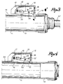
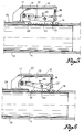
- Said drawing shows a breech 10 with barrel 10' of a fire arm, e.g. an automatic gun, and with a bolt 11 which is manually displaceable, by means of a slider 12, from a front and closed position resting against the barrel to a rear and open position defined by a tripping mechanism the moment in which the arm is to be used.
- a fire arm e.g. an automatic gun
- Said slider 12 is assembled to the breech 11 through a support 13 which is fixed to the breech and can thus be displaced together with it.
- Slider 12 is assembled and guided on support 13 and sliding in the direction in which the bolt is displaceable.
- Support 13 is inserted into a longitudinal slot 14 cut into the breech 10 to allow the opening and closing displacements of the bolt 11.
- At least at one end of said slot 14 the breech 10 is fitted with a sequence of teeth 15 sloping transversally to the sense of displacement of bolt 11.
- a slot 16 which is parallel to the axis of bolt 11 is provided to receive a pin 17 traversing the support 13 and thus the slider 12. Slot 16 and pin 17 cooperate in delimiting the sliding motions of slider 12 on support 13 and taking back said support with the bolt when the latter has to be manually taken into its open position. In the illustrated embodiment said rearward displacement of support 13 with bolt 11 is actually obtained by placing the front end 12' of the slider against the head of support 13.
- a spring 18 is normally keeping the slider 12 displaced to the front end of support 13, while the pin 17 is pushed against the front end of slot 16.
- a rocking catch lever 19 is pivoted on a pin 20, said pin crossing the direction in which bolt 11 is displaced.
- Said lever 19 is also subject to a spring 23 to normally keep its tooth 21 displaced towards the toothing 15 and its end 22 towards pin 17 or to engage it on said pin.
- the position of the components of said device is:
- the first stage of manual cocking comprises a pressure exercised in the direction of arrow F on slider 12 to slightly displace it (by 10 mm approx.) on its support 13 and thus in respect to bolt 11, support and bolt not moving during this first stage.
- the arm is thus in a static condition of partial opening of its bolt and at any rate in a safe position, while the trigger is fully indepennt from any motion of the bolt.
- the safety device is inactivated only with the bolt engaged in the tripping mechanism.
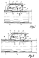
- a release plate 24 is fitted on the breech 11 after the rear end of toothing 15, said plate 24 interacting with the locking lever 19 so as to lift and displace it into its neutral position as soon as the bolt has reached its correct cocked position.
- the interaction of the release plate 24 with the rocking lever 19 is shown in Fig. 9 of the drawing where it can be seen how, on one hand, the catch tooth 21 of lever 19 is displaced by plate 14 - arrow H - above toothing 15 and, on the other hand, tail 22 of said lever is situated below pin 17 of slider 12.
- the arm is ready for shooting both single shots and automatically, while the safety device stays totally inert but always ready to exert its function as soon as the bolt of the arm has to be cocked again.
Landscapes
- Engineering & Computer Science (AREA)
- General Engineering & Computer Science (AREA)
- Portable Nailing Machines And Staplers (AREA)
- Vending Machines For Individual Products (AREA)
- Fire-Extinguishing By Fire Departments, And Fire-Extinguishing Equipment And Control Thereof (AREA)
- Jib Cranes (AREA)
- Centrifugal Separators (AREA)
- Toys (AREA)
Claims (5)
- Selbsttätige Sicherungsvorrichtung für Feuerwaffen, wie Maschinenpistolen, die mit ihrem Verschluß in der Offenstellung ausgehend und mit selbsttätiger Schußfolge oder mit Einzelfeuer funktionieren und deren Verschluß (11) von Hand ausgehend von einer vorgeschobenen Schließstellung mit Hilfe eines Schiebers (12) in einem Bodenstück (10) gegen den Gewehrlauf bis zu einer hinteren, durch eine Auslöseeinrichtung bestimmten Offenstellung verschiebbar ist, wobei das Bodenstück (10) mit einem Längsschlitz (14) versehen ist, an dessen mindestens einer Seite eine Verzahnung (15) vorgesehen ist, die aus einer Reihe von Zähnen besteht, die quer zur Richtung der Verschiebung des Verschlusses ausgerichtet sind, dadurch gekennzeichnet, daß an dem Verschluß (11) ein Träger (13) befestigt ist, der sich in den oben genannten Längsschlitz (14) hinein erstreckt, daß der Schieber (12) mit der Halterung verbunden ist und zwischen einer vorgeschobenen Stellung, in der er außer Eingriff mit dem Träger (13) steht, und einer rückwärtigen Stellung, in der er axial mit der Halterung eingreift, verschiebbar ist, um den Verschluß (11) in Richtung auf seine rückwärtige Offenstellung zu verschieben, daß auf diesem Träger (13) ein schwenkbarer Abstellhebel (19) angebracht ist, dessen eines Ende mit einem Sperrzahn (21) versehen ist, der mit der Verzahnung (15) zusammenwirkt, während sein entgegengesetztes Ende (22) mit einem auf dem Träger (13) befestigten und mit dem Schieber (12) verschiebbaren Stift (17) zusammenwirkt, und daß der Stift (17) des Schiebers (12) und der Abstellhebel (19) zusammenwirken, um dem Sperrzahn (21) des Abstellhebels (19) zu ermöglichen, mit der Verzahnung (15) einzugreifen, um das Vorlaufen des Verschlusses (11) bei Fehlbedienung bzw. beim Loslassen während seiner Verschiebung gegen die rückwärtige Offenstellung zu verhindern und um den Abstellhebel (19) während der Funktion der Waffe bei automatischem Schießen oder bei Einzelfeuer in einer unwirksamen Stellung zu halten, wobei dieser Abstellhebel unwirksam ist, wenn sich der Verschluß in seiner rückwärtigen Stellung auf der Auslöseeinrichtung befindet und sein Sperrzahn (21) mit der Verzahnung (15) nicht zusammenwirkt.
- Vorrichtung nach Anspruch 1, dadurch gekennzeichnet, daß ein Teil (12') des Schiebers (12) mit dem Träger (13) in Berührung kommt, wenn der Schieber (12) sich in seiner rückwärtigen Stellung befindet, um den Verschluß (11) in Richtung auf seine Offenstellung zu verschieben, und daß eine Rückholfeder (18) zwischen dem Schieber (12) und dem Träger (13) angeordnet ist, um den Schieber (12) in seiner vorgeschobenen Stellung zu halten und zurückzubringen, in der die Rückholfeder mit dem Träger (13) nicht mehr eingreift.
- Vorrichtung nach den Ansprüchen 1 und 2, dadurch gekennzeichnet, daß der Abstellhebel (19) von einer Feder (23) beansprucht wird, die bestrebt ist, den Sperrzahn (21) des Abstellhebels (19) in Richtung auf die Verzahnung (15) und das Ende (22) des Abstellhebels (19) in Zusammenwirkung mit dem auf dem Abstellhebel befindlichen Stift (17) zu halten und zu verschieben.
- Vorrichtung nach Anspruch 3, dadurch gekennzeichnet, daß das Ende (22) des Abstellhebels (19) und der Stift (17) auf der selben Höhe und in Abstand zueinander liegen, wenn der Schieber in seine rückwärtige Stellung auf dem Träger und der Verschluß in Richtung auf seine Offenstellung verschoben ist, und daß das Ende (22) des Abstellhebels (19) und der Stift (17) auf der selben Höhe liegen und miteinander in Berührung stehen, wenn der Schieber (12) sich in seiner vorgeschobenen Stellung befindet und der Sperrzahn (21) des Abstellhebels (19) mit der Verzahnung (15) zusammenwirkt, wobei hingegen das Ende (22) des Abstellhebels (19) sich unterhalb des Stiftes (17) abstützt, wenn der Schieber (12) sich in seiner vorgeschobenen Stellung befindet und der Abstellhebel unwirksam ist, so daß der Sperrzahn (21) entfernt von der Verzahnung (15) auf dem Bodenstück (10) gehalten wird.
- Vorrichtung nach Anspruch 1, dadurch gekennzeichnet, daß an dem Bodenstück (10) ein Plättchen (24) befestigt ist, das mit dem schwenkbaren Abstellhebel (19) zusammenwirkt, um ihn durch Entfernen seines Sperrzahnes (21) von der Verzahnung (15) unwirksam zu machen, wenn der Verschluß sich in seiner rückwärtigen Stellung auf der Auslöseeinrichtung befindet.
Priority Applications (1)
| Application Number | Priority Date | Filing Date | Title |
|---|---|---|---|
| AT89830560T ATE94275T1 (de) | 1989-01-11 | 1989-12-21 | Automatische sicherheitsvorrichtung fuer feuerwaffen. |
Applications Claiming Priority (2)
| Application Number | Priority Date | Filing Date | Title |
|---|---|---|---|
| IT8905101A IT1233383B (it) | 1989-01-11 | 1989-01-11 | Dispositivo di sicurezza automatico per armi da fuoco. |
| IT510189 | 1989-01-11 |
Publications (2)
| Publication Number | Publication Date |
|---|---|
| EP0378976A1 EP0378976A1 (de) | 1990-07-25 |
| EP0378976B1 true EP0378976B1 (de) | 1993-09-08 |
Family
ID=11117512
Family Applications (1)
| Application Number | Title | Priority Date | Filing Date |
|---|---|---|---|
| EP89830560A Expired - Lifetime EP0378976B1 (de) | 1989-01-11 | 1989-12-21 | Automatische Sicherheitsvorrichtung für Feuerwaffen |
Country Status (8)
| Country | Link |
|---|---|
| US (1) | US4977814A (de) |
| EP (1) | EP0378976B1 (de) |
| AT (1) | ATE94275T1 (de) |
| BR (1) | BR9000090A (de) |
| CA (1) | CA2007043C (de) |
| DE (1) | DE68909032T2 (de) |
| ES (1) | ES2044220T3 (de) |
| IT (1) | IT1233383B (de) |
Families Citing this family (6)
| Publication number | Priority date | Publication date | Assignee | Title |
|---|---|---|---|---|
| CA2151401C (en) * | 1993-10-08 | 1999-08-17 | Berthold Weichert | Self-loading grenade launcher |
| US5691497A (en) * | 1993-10-08 | 1997-11-25 | Heckler & Koch | Self-loading grenade launcher |
| DE10122345C1 (de) * | 2001-05-09 | 2002-10-31 | Heckler & Koch Gmbh | Maschinengewehr mit Spannschieber |
| US10012458B2 (en) | 2016-05-12 | 2018-07-03 | Smith & Wesson Corp. | Bolt for firearm |
| DE102018005354B3 (de) * | 2018-07-05 | 2019-12-19 | Heckler & Koch Gmbh | Verschlussfangvorrichtung mit Sperrvorrichtung einer Selbstladefeuerwaffe sowie damit ausgestaltetes Waffengriffstück und Waffengehäuse |
| EP4379306A1 (de) * | 2022-11-29 | 2024-06-05 | FN Herstal S.A. | Gesicherter ladehebel |
Family Cites Families (8)
| Publication number | Priority date | Publication date | Assignee | Title |
|---|---|---|---|---|
| BE502477A (de) * | 1950-04-15 | |||
| NL253134A (de) * | 1960-02-08 | |||
| FR1447906A (fr) * | 1961-05-19 | 1966-08-05 | Carl Walther O H G | Arme mécanique ou automatique munie d'un dispositif de sûreté |
| US3352206A (en) * | 1966-05-10 | 1967-11-14 | Iii Walter S Draper | Gun charger device |
| BE795653A (fr) * | 1973-02-19 | 1973-06-18 | Szultos Jozsef | Mitraillette perfectionnee |
| FR2231937B1 (de) * | 1973-06-01 | 1976-06-11 | Tellie Paul | |
| US4261247A (en) * | 1979-05-30 | 1981-04-14 | The United States Of America As Represented By The Secretary Of The Army | Double action charging mechanism |
| AT388239B (de) * | 1985-06-19 | 1989-05-26 | Steyr Daimler Puch Ag | Spannschieber fuer automatische handfeuerwaffen |
-
1989
- 1989-01-11 IT IT8905101A patent/IT1233383B/it active
- 1989-12-21 AT AT89830560T patent/ATE94275T1/de not_active IP Right Cessation
- 1989-12-21 DE DE89830560T patent/DE68909032T2/de not_active Expired - Fee Related
- 1989-12-21 ES ES89830560T patent/ES2044220T3/es not_active Expired - Lifetime
- 1989-12-21 EP EP89830560A patent/EP0378976B1/de not_active Expired - Lifetime
-
1990
- 1990-01-03 CA CA002007043A patent/CA2007043C/en not_active Expired - Fee Related
- 1990-01-10 US US07/462,812 patent/US4977814A/en not_active Expired - Fee Related
- 1990-01-10 BR BR909000090A patent/BR9000090A/pt not_active IP Right Cessation
Also Published As
| Publication number | Publication date |
|---|---|
| DE68909032D1 (de) | 1993-10-14 |
| CA2007043A1 (en) | 1990-07-11 |
| US4977814A (en) | 1990-12-18 |
| EP0378976A1 (de) | 1990-07-25 |
| ATE94275T1 (de) | 1993-09-15 |
| ES2044220T3 (es) | 1994-01-01 |
| BR9000090A (pt) | 1990-10-16 |
| DE68909032T2 (de) | 1994-01-20 |
| IT1233383B (it) | 1992-03-27 |
| IT8905101A0 (it) | 1989-01-11 |
| CA2007043C (en) | 2000-12-05 |
Similar Documents
| Publication | Publication Date | Title |
|---|---|---|
| US3745881A (en) | Combination slide latch and takedown mechanism for automatic pistol | |
| US4031648A (en) | Magazine safety and ejector | |
| US4291481A (en) | Firearm magazine safety mechanism | |
| US5448939A (en) | Firearm with multiple sears | |
| FR2680234A1 (fr) | Dispositif de commande multifonction d'arme a feu. | |
| GB1439309A (en) | Semi-automatic firearm | |
| US6519887B1 (en) | Magazine safety | |
| US3996685A (en) | Shell cut-off latch | |
| EP0013583B1 (de) | Pistole | |
| US4977814A (en) | Automatic safety device for fire arms | |
| US4090316A (en) | Firing pin safety device for hand firearms | |
| GB1560848A (en) | Self-loading pistol | |
| US5649383A (en) | Barrel retaining device for firearms | |
| US4016669A (en) | Firearm having trigger blocking mechanism | |
| US20250003709A1 (en) | Self-loading pistol with a pre-cocked firing pin with an assembly for safe disassembling | |
| EP0114826B1 (de) | Automatische handfeuerwaffe | |
| US4026056A (en) | Trigger release mechanism | |
| EP1106955B1 (de) | Feuerwaffe mit Inertialschlagbolzen | |
| US2203378A (en) | Firearm | |
| EP0356884A1 (de) | Schlagbolzenverriegelung an einer Feuerwaffe | |
| US2529359A (en) | Safety device for automatic pistols | |
| US1410248A (en) | Firing mechanism for firearms | |
| US4730538A (en) | Safety device for automatic firearms | |
| GB963120A (en) | Improvements in breech mechanisms for automatic firearms having a recoiling barrel | |
| EP0165053B1 (de) | Abdichtung in einer Feuerwaffe |
Legal Events
| Date | Code | Title | Description |
|---|---|---|---|
| PUAI | Public reference made under article 153(3) epc to a published international application that has entered the european phase |
Free format text: ORIGINAL CODE: 0009012 |
|
| AK | Designated contracting states |
Kind code of ref document: A1 Designated state(s): AT BE CH DE ES FR GB GR IT LI LU NL SE |
|
| 17P | Request for examination filed |
Effective date: 19901213 |
|
| 17Q | First examination report despatched |
Effective date: 19920316 |
|
| GRAA | (expected) grant |
Free format text: ORIGINAL CODE: 0009210 |
|
| ITF | It: translation for a ep patent filed | ||
| AK | Designated contracting states |
Kind code of ref document: B1 Designated state(s): AT BE CH DE ES FR GB GR IT LI LU NL SE |
|
| REF | Corresponds to: |
Ref document number: 94275 Country of ref document: AT Date of ref document: 19930915 Kind code of ref document: T |
|
| REF | Corresponds to: |
Ref document number: 68909032 Country of ref document: DE Date of ref document: 19931014 |
|
| ET | Fr: translation filed | ||
| EPTA | Lu: last paid annual fee | ||
| REG | Reference to a national code |
Ref country code: GR Ref legal event code: FG4A Free format text: 3009471 |
|
| REG | Reference to a national code |
Ref country code: ES Ref legal event code: FG2A Ref document number: 2044220 Country of ref document: ES Kind code of ref document: T3 |
|
| PLBE | No opposition filed within time limit |
Free format text: ORIGINAL CODE: 0009261 |
|
| STAA | Information on the status of an ep patent application or granted ep patent |
Free format text: STATUS: NO OPPOSITION FILED WITHIN TIME LIMIT |
|
| 26N | No opposition filed | ||
| EAL | Se: european patent in force in sweden |
Ref document number: 89830560.2 |
|
| PGFP | Annual fee paid to national office [announced via postgrant information from national office to epo] |
Ref country code: NL Payment date: 19971231 Year of fee payment: 9 |
|
| PGFP | Annual fee paid to national office [announced via postgrant information from national office to epo] |
Ref country code: LU Payment date: 19980115 Year of fee payment: 9 |
|
| PG25 | Lapsed in a contracting state [announced via postgrant information from national office to epo] |
Ref country code: LU Free format text: LAPSE BECAUSE OF NON-PAYMENT OF DUE FEES Effective date: 19981221 |
|
| PG25 | Lapsed in a contracting state [announced via postgrant information from national office to epo] |
Ref country code: NL Free format text: LAPSE BECAUSE OF NON-PAYMENT OF DUE FEES Effective date: 19990701 |
|
| NLV4 | Nl: lapsed or anulled due to non-payment of the annual fee |
Effective date: 19990701 |
|
| PGFP | Annual fee paid to national office [announced via postgrant information from national office to epo] |
Ref country code: GB Payment date: 20001027 Year of fee payment: 12 |
|
| PGFP | Annual fee paid to national office [announced via postgrant information from national office to epo] |
Ref country code: DE Payment date: 20001102 Year of fee payment: 12 |
|
| PGFP | Annual fee paid to national office [announced via postgrant information from national office to epo] |
Ref country code: BE Payment date: 20001117 Year of fee payment: 12 |
|
| PGFP | Annual fee paid to national office [announced via postgrant information from national office to epo] |
Ref country code: ES Payment date: 20001128 Year of fee payment: 12 |
|
| PGFP | Annual fee paid to national office [announced via postgrant information from national office to epo] |
Ref country code: FR Payment date: 20001130 Year of fee payment: 12 |
|
| PGFP | Annual fee paid to national office [announced via postgrant information from national office to epo] |
Ref country code: SE Payment date: 20001218 Year of fee payment: 12 |
|
| PGFP | Annual fee paid to national office [announced via postgrant information from national office to epo] |
Ref country code: AT Payment date: 20001229 Year of fee payment: 12 |
|
| PGFP | Annual fee paid to national office [announced via postgrant information from national office to epo] |
Ref country code: GR Payment date: 20010102 Year of fee payment: 12 |
|
| PGFP | Annual fee paid to national office [announced via postgrant information from national office to epo] |
Ref country code: CH Payment date: 20010308 Year of fee payment: 12 |
|
| PG25 | Lapsed in a contracting state [announced via postgrant information from national office to epo] |
Ref country code: GB Free format text: LAPSE BECAUSE OF NON-PAYMENT OF DUE FEES Effective date: 20011221 Ref country code: AT Free format text: LAPSE BECAUSE OF NON-PAYMENT OF DUE FEES Effective date: 20011221 |
|
| PG25 | Lapsed in a contracting state [announced via postgrant information from national office to epo] |
Ref country code: SE Free format text: LAPSE BECAUSE OF NON-PAYMENT OF DUE FEES Effective date: 20011222 |
|
| PG25 | Lapsed in a contracting state [announced via postgrant information from national office to epo] |
Ref country code: LI Free format text: LAPSE BECAUSE OF NON-PAYMENT OF DUE FEES Effective date: 20011231 Ref country code: GR Free format text: LAPSE BECAUSE OF NON-PAYMENT OF DUE FEES Effective date: 20011231 Ref country code: CH Free format text: LAPSE BECAUSE OF NON-PAYMENT OF DUE FEES Effective date: 20011231 Ref country code: BE Free format text: LAPSE BECAUSE OF NON-PAYMENT OF DUE FEES Effective date: 20011231 |
|
| REG | Reference to a national code |
Ref country code: GB Ref legal event code: IF02 |
|
| BERE | Be: lapsed |
Owner name: FABBRICA D'ARMI P. BERETTA S.P.A. Effective date: 20011231 |
|
| PG25 | Lapsed in a contracting state [announced via postgrant information from national office to epo] |
Ref country code: DE Free format text: LAPSE BECAUSE OF NON-PAYMENT OF DUE FEES Effective date: 20020702 |
|
| EUG | Se: european patent has lapsed |
Ref document number: 89830560.2 |
|
| GBPC | Gb: european patent ceased through non-payment of renewal fee |
Effective date: 20011221 |
|
| REG | Reference to a national code |
Ref country code: CH Ref legal event code: PL |
|
| PG25 | Lapsed in a contracting state [announced via postgrant information from national office to epo] |
Ref country code: FR Free format text: LAPSE BECAUSE OF NON-PAYMENT OF DUE FEES Effective date: 20020830 |
|
| REG | Reference to a national code |
Ref country code: FR Ref legal event code: ST |
|
| PG25 | Lapsed in a contracting state [announced via postgrant information from national office to epo] |
Ref country code: ES Free format text: LAPSE BECAUSE OF NON-PAYMENT OF DUE FEES Effective date: 20021222 |
|
| REG | Reference to a national code |
Ref country code: ES Ref legal event code: FD2A Effective date: 20030113 |
|
| PG25 | Lapsed in a contracting state [announced via postgrant information from national office to epo] |
Ref country code: IT Free format text: LAPSE BECAUSE OF NON-PAYMENT OF DUE FEES;WARNING: LAPSES OF ITALIAN PATENTS WITH EFFECTIVE DATE BEFORE 2007 MAY HAVE OCCURRED AT ANY TIME BEFORE 2007. THE CORRECT EFFECTIVE DATE MAY BE DIFFERENT FROM THE ONE RECORDED. Effective date: 20051221 |