EP0379073A2 - Vorrichtung zum Schützen und Verarbeiten von Banknoten und Wertgegenstände - Google Patents
Vorrichtung zum Schützen und Verarbeiten von Banknoten und Wertgegenstände Download PDFInfo
- Publication number
- EP0379073A2 EP0379073A2 EP90100572A EP90100572A EP0379073A2 EP 0379073 A2 EP0379073 A2 EP 0379073A2 EP 90100572 A EP90100572 A EP 90100572A EP 90100572 A EP90100572 A EP 90100572A EP 0379073 A2 EP0379073 A2 EP 0379073A2
- Authority
- EP
- European Patent Office
- Prior art keywords
- housing
- safety
- compartments
- mobile element
- valuables
- Prior art date
- Legal status (The legal status is an assumption and is not a legal conclusion. Google has not performed a legal analysis and makes no representation as to the accuracy of the status listed.)
- Granted
Links
Images



Classifications
-
- E—FIXED CONSTRUCTIONS
- E05—LOCKS; KEYS; WINDOW OR DOOR FITTINGS; SAFES
- E05G—SAFES OR STRONG-ROOMS FOR VALUABLES; BANK PROTECTION DEVICES; SAFETY TRANSACTION PARTITIONS
- E05G5/00—Bank protection devices
- E05G5/006—Cashier's counters or receptables for holding valuables readily accessible for handling, with safeguard mechanisms for the valuables in case of hold-up
-
- G—PHYSICS
- G07—CHECKING-DEVICES
- G07D—HANDLING OF COINS OR VALUABLE PAPERS, e.g. TESTING, SORTING BY DENOMINATIONS, COUNTING, DISPENSING, CHANGING OR DEPOSITING
- G07D11/00—Devices accepting coins; Devices accepting, dispensing, sorting or counting valuable papers
- G07D11/10—Mechanical details
- G07D11/14—Inlet or outlet ports
-
- G—PHYSICS
- G07—CHECKING-DEVICES
- G07D—HANDLING OF COINS OR VALUABLE PAPERS, e.g. TESTING, SORTING BY DENOMINATIONS, COUNTING, DISPENSING, CHANGING OR DEPOSITING
- G07D11/00—Devices accepting coins; Devices accepting, dispensing, sorting or counting valuable papers
- G07D11/20—Controlling or monitoring the operation of devices; Data handling
-
- G—PHYSICS
- G07—CHECKING-DEVICES
- G07D—HANDLING OF COINS OR VALUABLE PAPERS, e.g. TESTING, SORTING BY DENOMINATIONS, COUNTING, DISPENSING, CHANGING OR DEPOSITING
- G07D11/00—Devices accepting coins; Devices accepting, dispensing, sorting or counting valuable papers
- G07D11/20—Controlling or monitoring the operation of devices; Data handling
- G07D11/22—Means for sensing or detection
-
- G—PHYSICS
- G07—CHECKING-DEVICES
- G07G—REGISTERING THE RECEIPT OF CASH, VALUABLES, OR TOKENS
- G07G1/00—Cash registers
- G07G1/0018—Constructional details, e.g. of drawer, printing means, input means
- G07G1/0027—Details of drawer or money-box
-
- E—FIXED CONSTRUCTIONS
- E05—LOCKS; KEYS; WINDOW OR DOOR FITTINGS; SAFES
- E05G—SAFES OR STRONG-ROOMS FOR VALUABLES; BANK PROTECTION DEVICES; SAFETY TRANSACTION PARTITIONS
- E05G1/00—Safes or strong-rooms for valuables
- E05G1/06—Safes or strong-rooms for valuables having provision for multiple compartments
-
- E—FIXED CONSTRUCTIONS
- E05—LOCKS; KEYS; WINDOW OR DOOR FITTINGS; SAFES
- E05G—SAFES OR STRONG-ROOMS FOR VALUABLES; BANK PROTECTION DEVICES; SAFETY TRANSACTION PARTITIONS
- E05G1/00—Safes or strong-rooms for valuables
- E05G1/06—Safes or strong-rooms for valuables having provision for multiple compartments
- E05G1/08—Safes or strong-rooms for valuables having provision for multiple compartments secured individually
Definitions
- the present invention has the scope of supplying a device and a process for protecting and handling bank notes and valuables.
- a device used for protecting and handling bank notes and valuables including a housing and a protection casing forming the external walls of said housing, characterized in that it includes: at least a mobile element supported by said housing and having an extension direction and a plurality of safety compartments suitable for holding bank notes and valuables at least some of which are consecutive with one another along said extension direction, a sliding direction of said mobile element with respect to said protection housing, parallel to said extension direction and crossing at least an access position of said safety compartments from the outside of said protection housing, locking means for said mobile element internal to said protection housing and establishing a plurality of stop positions for said mobile element along said sliding direction, and a control device driving said locking means of said mobile element in a manner suitable for locating at choice said safety compartments in said access position.
- the process includes the location of said bank notes and valuables in a plurality of safety compartments, and allows the gradual access to the contents of said safety compartments according to prefixed timer-controlled sequences.
- the device according to the invention is generally indicated with the reference number 1 .
- This device includes a housing 2 , whose external walls are established by an armor-plating or protection housing 2a .
- the housing 2 supports mobile elements 3 that can be extracted along sliding directions parallel to the extension directions of the same mobile elements 3.
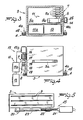
- the figures show the mobile elements 3 formed by drawers extractable from the protection housing 2a sliding along guide elements 4 .
- the Figures 1-4 show the guide elements 4 that are made-up of rollers 4a and rails 4b
- the Figure 8 shows the linear guides 4c .
- the rails 4b and the linear guides 4c establish the sliding direction of the drawers or mobile elements 3, perpendicular to a face of the housing 2 and parallel to the main extension direction of drawers 3.
- Each drawer 3 is divided in safety compartments 5 consecutive with one another and parallel to the sliding direction.
- the division is established by safety bulkheads 6 developping transversally to said sliding direction.
- the illustrated safety compartments 5 are sized in the measure of bank notes to be put thereinto, alternatively in horizontal or vertical directions, so that they can hold measured quantities thereof.
- the safety bulkheads 6 can be whether fixed or mobile, when this last solution does not damage the fastening of said bulkheads and prevents the movements thereof when the bulkheads are inserted, even only partially, into the protection housing 2a.
- position sensors 7 suitable for surveying the position of each drawer 3 with respect to the protection housing 2a.
- lock members 8 suitable for locking the drawers 3 in a plurality of positions with respect to the protection housing 2a, these positions of safety compartments 5 being protection or access positions of the said compartments from the outside of the protection housing 2a.
- Said protruding positions correspond to the gradual output of the safety compartments 5 from the housing 2a.
- the position sensors 7 form a part of a control device 11 that is suitable for actuating the lock members 8 and including further quantity sensing members 12 suitable for surveying the presence of bank notes or valuables in the safety compartments 5. Numerous advantageous technical solutions are possible in relation to the quantity sensors 12.
- the quantity sensors 12 shown in the Figures 1 and 2 include, in each safety compartment 5, an emitter and a receiver 12a , exchanging e.g. infrared signals or ultra-audible vibrations modulated according to a previously programmed code, located in opposed zones of each compartment 5, so that the content of each compartment inteferes with the same signals.
- the quantity sensors 12, shown in Figures 5, 6, 8 are external to the mobile elements or drawers 3 and located near the opposite sides of each drawer 3.
- each drawer 3 there are two or three couples of emitters and receivers 12a spaced with one another and engaged in a position protected in the inside of the housing 2a. They survey the content of safety compartments 5, to which they are external, by means of slots 9 machined in the sides of drawers 3.
- the Figures 6 and 8 show also that emitters and receivers 12a are positioned fixed near the front wall of the housing 2 and therefore they survey the presence of bank notes or valuables in safety compartments 5 during the extraction of the drawers 5 from the housing 2a.
- these couples of emitters and receivers 12a are located in a manner suitable for controlling zones of different heights in safety compartments 5 for emitting not only the signals referring to completely full compartments or completely empty compartments, but also signals indicating the filling level.
- the safety bulkheads 6 are made-up of wedge-shaped blocks flanked in alternated positions and spaced with one another for forming compartments sloping with respect to said sliding direction, so that even one single bank note, located sloping and laid in vertical or horizontal directions onto an edge thereof, can interfere with emitters and receivers 12a.
- said block-shaped safety bulkheads show grooves 6a located at the height of slots 9 and sized for establishing on the whole ports or operations having a direction mainly perpendicular to the sides or location edges of drawers 3, for making easier the surveys of emitters and receivers 12a, being these elements also aligned perpendicularly to the sides of drawers 3.
- quantity sensors 12 made up of a photovoltaic cell 12b , located onto the bottom of each safety compartment 5.
- the photovoltaic cell 12b can be dimmed by the content of compartment and on the contrary it can be activated by the ambient light, when the compartment is completely empty.
- quantity sensors 12 made up of wellknown load cells, suitable for surveying the load variations that occur internally to the whole drawer 3, or internally to each compartment 5, located between the bottom of the drawer 3 and a tray element establishing the common basis of one or more safety compartments 5.
- the control device 11 includes the position detectors 7 and the quantity sensors 12 are joined to logic circuits 11a , in which the informations transmitted by same position detectors 7 and by quantity sensors 12 are processed in function of the control of locking means 8.
- the logic circuits 11a include timing elements or circuits suitable for adjusting the lock means 8 according to prefixed time sequences, so that the gradual extraction of the safety compartments 5 is synchronized with the foreseen necessities of money drawing.
- the control device 11 is also interlocked with alarm and/or protection means, e.g. of acoustic type and external signaling members 10 for alerting the charged personnel.
- alarm and/or protection means e.g. of acoustic type and external signaling members 10 for alerting the charged personnel.
- Figures 2 and 3 show a fulfilment form of the device 1, in which the control device 11, the lock means 8 and also the electric feeding unit 13 are located in the inside of each drawer 3, occupying the sole last closed compartment 5a , as shown in Figure 2.
- this fulfilment form includes the control device 11 showing the position detectors 7, made up of proximity switches or sensors 7a , sensible to stops placed externally to the drawers 3, while the lock means 8 are made-up by an electrically driven piston 8a .
- This piston 8a shows a rod 8b that is engaged in proper holes 14a of a bar or pipe 14 , fixed and internal to the protection housing 2a.
- the Figure 4 shows a fulfilment form of the device 1, in which the control device 11, the lock means 8 and the electric feeding unit 13 are located at the outside of the drawers 3.
- the drive members 15 can move the mobile elements or drawers 3 in two opposed directions, for extracting automatically new safety compartments 5, when the housing 2 is in emptying phase, or for closing the just filled safety compartments 5, when the housing 2 is in even partial filling phase.
- the drive members 15 include, for each drawer 3, a reversible electric motor 15a that drives a gear 16 engaged with a rack 17 joined to the lateral side of the drawer 3.
- the control device 11, shown in Figure 4 includes position detectors 7 made-up by a position sensor 7b that measures the rotation of the gear 16.
- the various members of Figure 3 can be also installed externally to the drawer 3, while the members of Figure 4 can be internal to the drawer 3.
- the piston 8a ( Figure 3) can operate at the outside of the drawer 3, while the gear 16 ( Figure 4), located in the inside together with the electric motor 15a, can mesh with an external and fixed rack 17, through a slot made in the drawer 3.
- the lock means 8 of Figure 4 are formed by a stop element 18 that acts through tooths onto the position sensor 7b, joined to the gear 16. For controlling the axial movement of the stop element 18, there is an electromagnet 19 .
- the drive members 15 are made-up of linear actuators 20 parallel to the drawers 3 and driven by motor units 21 .
- the motor units 21 are preferably electrically driven geared motors and the linear actuators 20 are preferably telescopic rods: a first telescopic rod 22 in screw form, turned directly by a geared motor 21, and a second telescopic rod 23 is made in a bush or nut screw form, winding the first telescopic rod 22a and fixed externally to a mobile element or drawer 3.
- the telescopic rods 22a , 22b are extended between the front and bottom walls of the protection housing 2a, and the geared motors 21 are near to the bottom wall.
- the linear actuators 20 can be also of oleo-dynamic type and include oleo-dynamic pistons joined, by pipes, to an electrically driven pump.
- the drive members 15 shown in Figure 5 and 8 are suitable for moving the drawers 3 and for forming the locking means 8, as they can establish the fixed locking of drawers 3 by the simple stop of geared motors 21 that make progress the same drawers 3 in two directions.
- the mobile elements 3 can be moved manually in two directions, if and until the lock members 8 allow this movement.
- some handles 3a are in drawers 3, shown in Figures 1, 2, 4.
- the housing 2 is preferably mounted on wheels or rollers 24 , as shown in Figures 1, 7 and 8, for being moved easily, and it is supplied with location means 25 , partially positioned on ceiling ( Figure 7) or on pavement ( Figures 8-11).
- the Figure 7 shows a first location element 26a associated with the housing 2 and the second fixed location elements 26b , located on ceiling along paths foreseen according to prefixed positions and handlings of the housing 2.
- the location elements 26a and 26b include some transmission and receiving devices 27 , suitable for emitting and/or receiving infrared rays or radio waves or ultra-audible vibrations, that cause position signals.
- the Figure 7 shows that the second location elements 26a are spaced with one another and therefore the sole element 26b overlapping the housing 2 surveys the presence of the same housing 2 and communicates with the same housing by means of the devices 27.
- the receiving and transmitting devices 27 are preferably suitable for communicating also the signals indicating the condition of drawers 3 to a control device 28 .
- the control device 28 that in the illustrated symbolic execution is separated from the housing 2 and located on ceiling, includes both the clock and calendar circuits 29 suitable for sending time signals, and logic circuits 30 , suitable for processing and controlling the position signals and the state signals corresponding to closing and opening positions of drawers 3. Further there are alarm elements, including an acoustic buzzer 31 , interlocked to the control device 28.
- the Figure 8 shows that the housing 2 can be positioned in the stations 32 placed on pavement.
- the stations 32 are located in the terminal zones where it is required the positioning of housing 2 or in the start zone thereof or also along the paths followed by the housing 2 during its movements.
- the housing 2 of Figure 8 shows location means 25 activated towards the stations 32 and including, under a bottom face, a first sensing device 33 , having some electric contact terminals, suitable for causing position signals when it is put in contact with a corresponding second sensing device 34 machined in the stations 32.
- the fulfilment form shown in Figures 9, 10, and 11 includes the electric contacts of the first sensing device that are shaped in circumference arc and the second sensing device 34 that is defined by contact elements suitable for assuring an elastic contact in vertical direction.
- the stations 32 there are some conductive balls 34a inserted in bushes 32a made of insulating material.
- Each conductive ball 34a is spring-loaded by a spring 34b introduced into the bush 32a and electrically conductive and further electrically joined with a cable 34c .
- the control device 28 is joined with the cables 34c and the first sensing device 33 can emit also recognizing signals that locate the housing 2 present in each one of the stations 32.
- locking means fixing the housing 2 to the ground, including a coupler device 35 ( Figure 11) located in conjuction with the bottom of the housing 2 and suitable for being engaged with a projection 36 fixed and protruding from the station 32.
- the coupler device 35 includes a seat 37 gradually narrowing until a reduced bottom 37a and a closing member 38 supplied with a stem 38a mobile and electrically or hydraulically driven, suitable for insulating the reduced bottom 37a.
- the expansion 36 showing a stem 39 dimensioned according to the reduced bottom 37a and ending with an expanded bulb 40 preventing the lifting of the housing 2, can be inserted into the seat 37.
- the closing member 38 of the coupler device 35 is driven directly by the control device 11 or by the control device 28.
- the running of the device occurs as follows. During the initial introduction phase of valuables or generical bank notes, the mobile elements are closed gradually, compartment by compartment, when each compartment is filled.
- the closing can be made directly by an operator, that, after having filled a safety compartment 5, inserts the same compartment into the more near introduction and protection position in the inside of the protection housing 2a, signaling, e.g. by the signaling members 10, that the just inserted safety compartment 5 is filled. This signal causes the operation of locking means 8.
- the device 1 is supplied with quantity sensors 12 and the signal of filled compartment is sent automatically by the quantity sensors 12.
- the device 1 is supplied with drive members 15 and position detectors 7 and therefore all movements of drawers can be controlled automatically.
- control device 11 When the control device 11 is supplied with quantity sensors 12, it is possible to foresee that the filled or not empty safety compartment 5 can be freely accessible and that eventually only a second more internal consecutive compartment can be also extracted freely from the protection housing 2a in a manner suitable for guaranteeing a certain availability of bank notes or valuables.
- the other more internal compartments shall become gradually accessible only when the quantity sensing members 12 of accessible external compartments shall have supplied suitable indications to the control device 11, e.g. showing the empty compartment and above all when a minimum prefixed time interval from the opening of more external compartments shall be over.
- the loading and closing operations and the opening and drawing operations can be alternated with one another, as it is always possible to charge one or more safety compartments 5 and getting, automatically or manually, the immediate insertion of compartments as soon as they are loaded into the protection housing 2a. As soon as these compartments are inserted into the protection housing 2a, they are treated as all other compartments and therefore they are accessible only when the adjacent compartments are empty and it was elapsed the minimum time foreseen for the emptying of the same compartments.
- the control device 28 receives the position signals of housing 2. These signals are compared with data related to positions prefixed versus time. If disagreements between the position signals and said data are surveyed, then alarm means, e.g. the acoustic buzzer 31, are activated.
- the housing 2 can be joined fixedly to one station 32 by locking means 35, 36, using the closing member 38.
- the possibility of movement of the device 1 and the presence of location means 25 make possible in particular the loading of various drawers 3 in protected positions of a bank and a transport in safety conditions, e.g. towards the various bank counters.
- the invention fulfils also a new process that allows the insertion of bank notes and valuables in a plurality of singularly protected safety compartments 5, and making gradually accessible the same safety compartments according to prefixed timer-controlled sequences.
- the opening and drawing phases are made in all said safety compartments that were submitted to the filling and closing phases, indipendently from the execution times of the filling and closing phases.
- the just closed and protected safety compartments 5 are similar with other just filled compartments. Therefore they can be opened again only respecting the foreseen time sequences.
- the invention fulfils important advantages.
- the device fulfils on one side an efficient protection against the abusive removals of valuables hold therein, limiting greatly the losses and on the other side it is simple and functional and suitable for many situations.
- time intervals necessary for making gradually accessible new filled safety compartments can be programmed according to specifical experimented or foreseable work necessities.
- housing 2 can be used both as fixed installation and as means for transporting valuables.
Landscapes
- Physics & Mathematics (AREA)
- General Physics & Mathematics (AREA)
- Business, Economics & Management (AREA)
- Accounting & Taxation (AREA)
- Finance (AREA)
- Purses, Travelling Bags, Baskets, Or Suitcases (AREA)
- Lock And Its Accessories (AREA)
- Drawers Of Furniture (AREA)
- Burglar Alarm Systems (AREA)
- Respiratory Apparatuses And Protective Means (AREA)
Applications Claiming Priority (8)
| Application Number | Priority Date | Filing Date | Title |
|---|---|---|---|
| IT1912289 | 1989-01-19 | ||
| IT8919122A IT1228483B (it) | 1989-01-19 | 1989-01-19 | Impianto di sicurezza per la detenzione e la movimentazione di valori e documenti. |
| IT8919324A IT1228294B (it) | 1989-02-06 | 1989-02-06 | Dispositivo di sicurezza a cassetti per il contenimento di banconote e valori in genere. |
| IT1932489 | 1989-02-06 | ||
| IT8919744A IT1228364B (it) | 1989-03-13 | 1989-03-13 | Impianto per il controllo della posizione di contenitori di sicurezza. |
| IT1974489 | 1989-03-13 | ||
| IT2056289 | 1989-05-19 | ||
| IT8920562A IT1230839B (it) | 1989-05-19 | 1989-05-19 | Dispositivo di sicurezza perfezionato per il contenimento di banconote e valori. |
Publications (3)
| Publication Number | Publication Date |
|---|---|
| EP0379073A2 true EP0379073A2 (de) | 1990-07-25 |
| EP0379073A3 EP0379073A3 (de) | 1991-07-03 |
| EP0379073B1 EP0379073B1 (de) | 1994-11-30 |
Family
ID=27452758
Family Applications (1)
| Application Number | Title | Priority Date | Filing Date |
|---|---|---|---|
| EP90100572A Expired - Lifetime EP0379073B1 (de) | 1989-01-19 | 1990-01-12 | Vorrichtung zum Schützen und Verarbeiten von Banknoten und Wertgegenstände |
Country Status (11)
| Country | Link |
|---|---|
| US (1) | US5087107A (de) |
| EP (1) | EP0379073B1 (de) |
| JP (1) | JPH02261184A (de) |
| AR (1) | AR244843A1 (de) |
| AT (1) | ATE114846T1 (de) |
| AU (1) | AU629894B2 (de) |
| BR (1) | BR9000190A (de) |
| CA (1) | CA2007989A1 (de) |
| DE (1) | DE69014319T2 (de) |
| ES (1) | ES2066885T3 (de) |
| PT (1) | PT92911A (de) |
Cited By (7)
| Publication number | Priority date | Publication date | Assignee | Title |
|---|---|---|---|---|
| FR2669310A1 (fr) * | 1990-11-16 | 1992-05-22 | Elce | Dispositif pour stocker des objets. |
| ES2052432A2 (es) * | 1992-02-07 | 1994-07-01 | Estivill Emilio Pascual | Dispositivo anti-atraco. |
| EP0950990A3 (de) * | 1998-04-13 | 2001-06-20 | Fujitsu Limited | Bankautomat |
| AU776998B2 (en) * | 1999-04-19 | 2004-09-30 | Australian Postal Corporation | Money dispenser, method of dispensing money and method of controlling an amount of money available for dispensing |
| GB2406092A (en) * | 2003-09-17 | 2005-03-23 | Coplan Ltd | An inventory control system for monitoring, by means of sensors, the removal and replacement of tools |
| GB2431963A (en) * | 2005-11-07 | 2007-05-09 | Contacta Ltd | A secure storage unit for bank notes |
| WO2022126206A1 (en) * | 2020-12-18 | 2022-06-23 | Jason Augustin Korda | Retractable housing assembly |
Families Citing this family (49)
| Publication number | Priority date | Publication date | Assignee | Title |
|---|---|---|---|---|
| US5440999A (en) * | 1992-06-03 | 1995-08-15 | Dallman Industrial Corporation | Modular transport system for an automatic teller machine |
| US6130621A (en) * | 1992-07-09 | 2000-10-10 | Rsa Security Inc. | Method and apparatus for inhibiting unauthorized access to or utilization of a protected device |
| US5392951A (en) * | 1993-05-20 | 1995-02-28 | Lionville Systems, Inc. | Drawer operating system |
| USD423181S (en) * | 1998-11-25 | 2000-04-18 | Dallman Industrial Corporation | Automatic teller machine (ATM) surround |
| US6000806A (en) * | 1994-05-10 | 1999-12-14 | Dallman Industrial Corporation | Lighting apparatus for an ATM kiosk |
| AU3638495A (en) * | 1994-09-28 | 1996-04-19 | Kvm Technologies, Inc. | Secure medication storage and retrieval system |
| US5971593A (en) | 1994-12-16 | 1999-10-26 | Diebold, Incorporated | Dispensing system for medical items |
| US5820234A (en) * | 1995-02-07 | 1998-10-13 | Hurd Corporation | Programmable electronic desk lock |
| US5716114A (en) * | 1996-06-07 | 1998-02-10 | Pyxis Corporation | Jerk-resistant drawer operating system |
| US5787819A (en) * | 1996-07-30 | 1998-08-04 | M.I.B. Elettronica S.R.L. | Anti-effraction device, in particular for automatic dispensers of banknotes and valuables |
| US5813736A (en) * | 1996-09-12 | 1998-09-29 | Ballew; Ann | Cabinet storage device |
| NO970853L (no) * | 1997-02-26 | 1998-08-27 | Jan Henrik Ulvik | Anordning ved kassa-apparat |
| USD421826S (en) * | 1998-11-25 | 2000-03-21 | Dallman Industrial Corporation | Light fixture for an ATM kiosk or surround |
| ATE262816T1 (de) * | 2000-02-14 | 2004-04-15 | Fulterer Gmbh | Möbel mit einer motorbetriebenen ausziehvorrichtung |
| GB0009484D0 (en) * | 2000-04-17 | 2000-06-07 | Secure Options Ltd | A security system |
| GB0108608D0 (en) * | 2001-04-05 | 2001-05-23 | Alpa Ind Ltd | Security storage device |
| US6785589B2 (en) | 2001-11-30 | 2004-08-31 | Mckesson Automation, Inc. | Dispensing cabinet with unit dose dispensing drawer |
| DE20204164U1 (de) * | 2002-03-14 | 2002-06-13 | Deutsche Post AG, 53175 Bonn | Regalsystem |
| US20030222548A1 (en) * | 2002-05-31 | 2003-12-04 | Richardson William R. | Storage device for health care facility |
| US20030201697A1 (en) * | 2002-04-30 | 2003-10-30 | Richardson William R. | Storage device for health care facility |
| AT500362B1 (de) * | 2002-06-27 | 2007-01-15 | Blum Gmbh Julius | Anordnung mit einem bewegbaren möbelteil und mit einer antriebseinheit |
| EP1538951B1 (de) * | 2002-08-07 | 2018-11-28 | SupplyPro, Inc. | Gerät zur sicherung von schubladeninhalten |
| US7142944B2 (en) * | 2002-08-07 | 2006-11-28 | Supplypro, Inc. | Apparatus for securing drawer contents |
| CA2404764A1 (en) * | 2002-09-24 | 2004-03-24 | Better Electrical Products (Hk) Company Limited | A casing for an electric appliance and an electric appliance with such a casing |
| AT502574B1 (de) * | 2003-05-19 | 2007-08-15 | Blum Gmbh Julius | Möbel mit einem bewegbaren möbelteil |
| WO2005073492A1 (ja) * | 2004-01-30 | 2005-08-11 | Thk Co., Ltd | 移動体駆動装置及び自動引出し装置 |
| US7293673B2 (en) * | 2004-09-08 | 2007-11-13 | Supplypro, Inc. | Drawer item dispenser |
| KR100700776B1 (ko) * | 2005-03-02 | 2007-03-27 | 엘지전자 주식회사 | 냉장고, 냉장고의 도어제어장치 및 도어제어방법 |
| AT502097B1 (de) * | 2005-07-12 | 2010-01-15 | Blum Gmbh Julius | Möbel mit ausstossvorrichtung für schubladen |
| AT503248B1 (de) * | 2006-03-03 | 2011-07-15 | Blum Gmbh Julius | Anordnung mit elektrischen antriebseinheiten für schubladen |
| AT503880A1 (de) * | 2006-06-22 | 2008-01-15 | Blum Gmbh Julius | Einzugsvorrichtung für eine schublade |
| US7693603B2 (en) * | 2007-01-22 | 2010-04-06 | John David Higham | Pharmaceutical dispensing system with coordinate guidance |
| US7823993B2 (en) * | 2007-04-03 | 2010-11-02 | Carefusion 303, Inc. | Piezo actuated slide latching mechanism |
| US7901017B1 (en) * | 2007-07-02 | 2011-03-08 | Corry Contract, Inc. | Security file cabinet with self-closing, self-locking drawers |
| US8061790B2 (en) * | 2007-12-20 | 2011-11-22 | General Electric Company | Powered drawer for an appliance |
| US8067915B2 (en) | 2008-12-31 | 2011-11-29 | General Electric Company | Electronic control circuit for a powered appliance drawer |
| US8744621B2 (en) | 2009-01-09 | 2014-06-03 | Automed Technologies, Inc. | Medical cabinet access belt optimization system |
| US8103379B2 (en) | 2009-01-09 | 2012-01-24 | Automed Technologies, Inc. | Medication cabinetry |
| US9121197B2 (en) * | 2009-01-09 | 2015-09-01 | Automed Technologies, Inc. | Cabinet system with improved drawer security |
| US8588966B2 (en) | 2009-01-09 | 2013-11-19 | Automed Technologies, Inc. | Cabinet system |
| US8262174B2 (en) * | 2009-06-05 | 2012-09-11 | Carefusion 303, Inc. | Multi-latch release mechanism |
| US8746908B2 (en) | 2010-01-27 | 2014-06-10 | Automed Technologies, Inc. | Medical supply cabinet with lighting features |
| US8662606B2 (en) * | 2011-03-17 | 2014-03-04 | Mckesson Automation Inc. | Drawer assembly and associated method for controllably limiting the slideable extension of a drawer |
| AU2012347950B2 (en) * | 2011-12-05 | 2016-02-11 | United States Postal Service | A system and method of control of electronic parcel lockers |
| DE112013004696A5 (de) * | 2012-09-25 | 2015-07-02 | Ecos Systems Gmbh | Schranksystem |
| CN104003048B (zh) * | 2014-05-20 | 2016-08-24 | 无锡瑞巴斯医疗器械有限公司 | 一种移动药箱 |
| CN112401523A (zh) * | 2021-01-18 | 2021-02-26 | 济源职业技术学院 | 一种经济管理用文件存放装置 |
| US11781757B2 (en) * | 2021-05-05 | 2023-10-10 | Whirlpool Corporation | Automatic rack system for a cooking appliance |
| CN115288563B (zh) * | 2022-07-12 | 2024-04-12 | 江西金虎保险设备集团有限公司 | 一种便于运输的银行业务库 |
Family Cites Families (12)
| Publication number | Priority date | Publication date | Assignee | Title |
|---|---|---|---|---|
| US1742542A (en) * | 1929-04-16 | 1930-01-07 | Edward N Howell | Key-filing device |
| US2707666A (en) * | 1950-10-24 | 1955-05-03 | Becker Otto Alfred | Device for conveying or transferring classified objects, in particular files, index cards or the like |
| IT555072A (de) * | 1956-03-16 | 1900-01-01 | ||
| US2964370A (en) * | 1956-09-17 | 1960-12-13 | Edward J Butler | Automatic reminder |
| NL135620C (de) * | 1963-12-02 | |||
| US3378321A (en) * | 1966-03-31 | 1968-04-16 | Supreme Steel Equipment Corp | Filing cabinets |
| DE8217330U1 (de) * | 1982-06-16 | 1982-12-16 | Karl, Kurt, 6073 Egelsbach | Hartgeld und valutatresor fuer automatische kassenanlagen |
| ES2012357B3 (es) * | 1985-12-05 | 1990-03-16 | Vidmar Ag | Instalacion de seguridad para deposito de valores. |
| DE3546341A1 (de) * | 1985-12-30 | 1987-07-02 | Werner Stadler | Tresor |
| US4934767A (en) * | 1986-05-16 | 1990-06-19 | Thermco Systems, Inc. | Semiconductor wafer carrier input/output drawer |
| FR2605040A1 (fr) * | 1986-10-14 | 1988-04-15 | Gen Equipement Internal Sa | Dispositif de securite antivol. |
| EP0310557A1 (de) * | 1987-09-29 | 1989-04-05 | Vidmar AG | Sicherheitsanlage zur Aufbewahrung von Wertsachen |
-
1990
- 1990-01-12 AT AT90100572T patent/ATE114846T1/de not_active IP Right Cessation
- 1990-01-12 EP EP90100572A patent/EP0379073B1/de not_active Expired - Lifetime
- 1990-01-12 DE DE69014319T patent/DE69014319T2/de not_active Expired - Fee Related
- 1990-01-12 ES ES90100572T patent/ES2066885T3/es not_active Expired - Lifetime
- 1990-01-17 CA CA002007989A patent/CA2007989A1/en not_active Abandoned
- 1990-01-17 AU AU48528/90A patent/AU629894B2/en not_active Ceased
- 1990-01-17 US US07/466,524 patent/US5087107A/en not_active Expired - Lifetime
- 1990-01-18 AR AR90315974A patent/AR244843A1/es active
- 1990-01-18 BR BR909000190A patent/BR9000190A/pt unknown
- 1990-01-19 PT PT92911A patent/PT92911A/pt not_active Application Discontinuation
- 1990-01-19 JP JP2008531A patent/JPH02261184A/ja active Pending
Cited By (8)
| Publication number | Priority date | Publication date | Assignee | Title |
|---|---|---|---|---|
| FR2669310A1 (fr) * | 1990-11-16 | 1992-05-22 | Elce | Dispositif pour stocker des objets. |
| ES2052432A2 (es) * | 1992-02-07 | 1994-07-01 | Estivill Emilio Pascual | Dispositivo anti-atraco. |
| EP0950990A3 (de) * | 1998-04-13 | 2001-06-20 | Fujitsu Limited | Bankautomat |
| AU776998B2 (en) * | 1999-04-19 | 2004-09-30 | Australian Postal Corporation | Money dispenser, method of dispensing money and method of controlling an amount of money available for dispensing |
| GB2406092A (en) * | 2003-09-17 | 2005-03-23 | Coplan Ltd | An inventory control system for monitoring, by means of sensors, the removal and replacement of tools |
| GB2406092B (en) * | 2003-09-17 | 2005-10-19 | Coplan Ltd | Inventory control system |
| GB2431963A (en) * | 2005-11-07 | 2007-05-09 | Contacta Ltd | A secure storage unit for bank notes |
| WO2022126206A1 (en) * | 2020-12-18 | 2022-06-23 | Jason Augustin Korda | Retractable housing assembly |
Also Published As
| Publication number | Publication date |
|---|---|
| ATE114846T1 (de) | 1994-12-15 |
| PT92911A (pt) | 1991-09-30 |
| BR9000190A (pt) | 1990-11-06 |
| EP0379073A3 (de) | 1991-07-03 |
| EP0379073B1 (de) | 1994-11-30 |
| AU629894B2 (en) | 1992-10-15 |
| CA2007989A1 (en) | 1990-07-19 |
| US5087107A (en) | 1992-02-11 |
| ES2066885T3 (es) | 1995-03-16 |
| AR244843A1 (es) | 1993-11-30 |
| DE69014319T2 (de) | 1995-05-18 |
| JPH02261184A (ja) | 1990-10-23 |
| AU4852890A (en) | 1990-07-26 |
| DE69014319D1 (de) | 1995-01-12 |
Similar Documents
| Publication | Publication Date | Title |
|---|---|---|
| EP0379073B1 (de) | Vorrichtung zum Schützen und Verarbeiten von Banknoten und Wertgegenstände | |
| US3964577A (en) | Automated handling system for bank deposit boxes | |
| US9260245B2 (en) | System and method for automatic storage and withdrawal of products with security restrictions | |
| US4363279A (en) | Method of positively controlling, storing and transporting banknotes, and a safety cassette and banknote-infeed unit for carrying out the method | |
| US4183708A (en) | High security systems for protecting valuable or dangerous consignments from theft | |
| BRPI0904631A2 (pt) | instalação de paletização combinada com acesso protegido | |
| US20020140223A1 (en) | High-security terminal for pneumatic-tube conveyor | |
| EP3661861B1 (de) | Selektive zugangsvorrichtung für eine aufnahme-/ablagestation in einem lager und mit einer solchen selektiven zugangsvorrichtung versehene aufnahme-/ablagestation | |
| CA1298520C (en) | Safe-deposit installation | |
| US4429639A (en) | Money-dispensing device from a safe's space | |
| EP0047659A2 (de) | Sicherheitsdurchgabevorrichtungen | |
| EP1961903A2 (de) | Gestell für den Transport von Wertgegenständen | |
| JP7140708B2 (ja) | 宅配ボックス | |
| CA1118643A (en) | Armor plated safe | |
| EP0269731B1 (de) | Geldlager-struktur | |
| JPS6030831B2 (ja) | 書籍等の格納庫 | |
| EP0265996A1 (de) | Sicherheitstresor | |
| CZ282047B6 (cs) | Časově blokovaná schránka pro zajištění zásob bankovek | |
| EP0092563A1 (de) | Sicherheitsanordnungen für einen behälter für wertpapiere insbesondere geld | |
| WO1988004086A1 (en) | An article cassette for a vending machine | |
| GB2249544A (en) | Warehouse storage control system | |
| JP2612052B2 (ja) | 自動販売機の商品搬出装置 | |
| ES2143942A1 (es) | Dispensador de cartuchos de monedas y similares. | |
| JPS6476185A (en) | Coin storage feeder | |
| JPH0813915A (ja) | 保管庫収納装置 |
Legal Events
| Date | Code | Title | Description |
|---|---|---|---|
| PUAI | Public reference made under article 153(3) epc to a published international application that has entered the european phase |
Free format text: ORIGINAL CODE: 0009012 |
|
| AK | Designated contracting states |
Kind code of ref document: A2 Designated state(s): AT BE CH DE DK ES FR GB GR LI LU NL SE |
|
| PUAL | Search report despatched |
Free format text: ORIGINAL CODE: 0009013 |
|
| AK | Designated contracting states |
Kind code of ref document: A3 Designated state(s): AT BE CH DE DK ES FR GB GR LI LU NL SE |
|
| 17P | Request for examination filed |
Effective date: 19911204 |
|
| 17Q | First examination report despatched |
Effective date: 19930720 |
|
| GRAA | (expected) grant |
Free format text: ORIGINAL CODE: 0009210 |
|
| AK | Designated contracting states |
Kind code of ref document: B1 Designated state(s): AT BE CH DE DK ES FR GB GR LI LU NL SE |
|
| PG25 | Lapsed in a contracting state [announced via postgrant information from national office to epo] |
Ref country code: NL Effective date: 19941130 Ref country code: GR Free format text: LAPSE BECAUSE OF FAILURE TO SUBMIT A TRANSLATION OF THE DESCRIPTION OR TO PAY THE FEE WITHIN THE PRESCRIBED TIME-LIMIT Effective date: 19941130 Ref country code: DK Effective date: 19941130 Ref country code: BE Effective date: 19941130 Ref country code: AT Effective date: 19941130 |
|
| REF | Corresponds to: |
Ref document number: 114846 Country of ref document: AT Date of ref document: 19941215 Kind code of ref document: T |
|
| REF | Corresponds to: |
Ref document number: 69014319 Country of ref document: DE Date of ref document: 19950112 |
|
| PGFP | Annual fee paid to national office [announced via postgrant information from national office to epo] |
Ref country code: SE Payment date: 19950130 Year of fee payment: 6 |
|
| PG25 | Lapsed in a contracting state [announced via postgrant information from national office to epo] |
Ref country code: LU Free format text: LAPSE BECAUSE OF NON-PAYMENT OF DUE FEES Effective date: 19950131 |
|
| ET | Fr: translation filed | ||
| PGFP | Annual fee paid to national office [announced via postgrant information from national office to epo] |
Ref country code: CH Payment date: 19950307 Year of fee payment: 6 |
|
| REG | Reference to a national code |
Ref country code: ES Ref legal event code: FG2A Ref document number: 2066885 Country of ref document: ES Kind code of ref document: T3 |
|
| NLV1 | Nl: lapsed or annulled due to failure to fulfill the requirements of art. 29p and 29m of the patents act | ||
| PLBE | No opposition filed within time limit |
Free format text: ORIGINAL CODE: 0009261 |
|
| STAA | Information on the status of an ep patent application or granted ep patent |
Free format text: STATUS: NO OPPOSITION FILED WITHIN TIME LIMIT |
|
| 26N | No opposition filed | ||
| PG25 | Lapsed in a contracting state [announced via postgrant information from national office to epo] |
Ref country code: SE Effective date: 19960113 |
|
| PG25 | Lapsed in a contracting state [announced via postgrant information from national office to epo] |
Ref country code: LI Effective date: 19960131 Ref country code: CH Effective date: 19960131 |
|
| PGFP | Annual fee paid to national office [announced via postgrant information from national office to epo] |
Ref country code: ES Payment date: 19960611 Year of fee payment: 7 |
|
| REG | Reference to a national code |
Ref country code: CH Ref legal event code: PL |
|
| EUG | Se: european patent has lapsed |
Ref document number: 90100572.8 |
|
| PG25 | Lapsed in a contracting state [announced via postgrant information from national office to epo] |
Ref country code: ES Free format text: LAPSE BECAUSE OF EXPIRATION OF PROTECTION Effective date: 19970113 |
|
| REG | Reference to a national code |
Ref country code: ES Ref legal event code: FD2A Effective date: 20000601 |
|
| REG | Reference to a national code |
Ref country code: GB Ref legal event code: IF02 |
|
| PGFP | Annual fee paid to national office [announced via postgrant information from national office to epo] |
Ref country code: FR Payment date: 20031230 Year of fee payment: 15 |
|
| PGFP | Annual fee paid to national office [announced via postgrant information from national office to epo] |
Ref country code: GB Payment date: 20040107 Year of fee payment: 15 |
|
| PGFP | Annual fee paid to national office [announced via postgrant information from national office to epo] |
Ref country code: DE Payment date: 20040127 Year of fee payment: 15 |
|
| PG25 | Lapsed in a contracting state [announced via postgrant information from national office to epo] |
Ref country code: GB Free format text: LAPSE BECAUSE OF NON-PAYMENT OF DUE FEES Effective date: 20050112 |
|
| PG25 | Lapsed in a contracting state [announced via postgrant information from national office to epo] |
Ref country code: DE Free format text: LAPSE BECAUSE OF NON-PAYMENT OF DUE FEES Effective date: 20050802 |
|
| GBPC | Gb: european patent ceased through non-payment of renewal fee |
Effective date: 20050112 |
|
| PG25 | Lapsed in a contracting state [announced via postgrant information from national office to epo] |
Ref country code: FR Free format text: LAPSE BECAUSE OF NON-PAYMENT OF DUE FEES Effective date: 20050930 |
|
| REG | Reference to a national code |
Ref country code: FR Ref legal event code: ST |