EP0379079A1 - - Appareil pour l'arpentage de la surface d'un objet par projection des dessins à bandes - Google Patents
- Appareil pour l'arpentage de la surface d'un objet par projection des dessins à bandes Download PDFInfo
- Publication number
- EP0379079A1 EP0379079A1 EP90100588A EP90100588A EP0379079A1 EP 0379079 A1 EP0379079 A1 EP 0379079A1 EP 90100588 A EP90100588 A EP 90100588A EP 90100588 A EP90100588 A EP 90100588A EP 0379079 A1 EP0379079 A1 EP 0379079A1
- Authority
- EP
- European Patent Office
- Prior art keywords
- phi
- values
- brightness
- points
- lambda
- Prior art date
- Legal status (The legal status is an assumption and is not a legal conclusion. Google has not performed a legal analysis and makes no representation as to the accuracy of the status listed.)
- Granted
Links
- 238000000034 method Methods 0.000 claims abstract description 16
- 238000009826 distribution Methods 0.000 claims description 33
- 230000015654 memory Effects 0.000 claims description 12
- 238000005286 illumination Methods 0.000 claims description 10
- 238000005259 measurement Methods 0.000 claims description 6
- 230000000737 periodic effect Effects 0.000 claims description 5
- 238000006073 displacement reaction Methods 0.000 claims description 4
- 230000006870 function Effects 0.000 claims description 4
- 230000015572 biosynthetic process Effects 0.000 claims 1
- 230000005622 photoelectricity Effects 0.000 claims 1
- 238000011156 evaluation Methods 0.000 description 6
- 230000003287 optical effect Effects 0.000 description 5
- 238000010586 diagram Methods 0.000 description 2
- 238000006243 chemical reaction Methods 0.000 description 1
- 230000001419 dependent effect Effects 0.000 description 1
- 238000011161 development Methods 0.000 description 1
- 230000018109 developmental process Effects 0.000 description 1
- 230000000694 effects Effects 0.000 description 1
- 238000000691 measurement method Methods 0.000 description 1
- 230000010363 phase shift Effects 0.000 description 1
- 239000011295 pitch Substances 0.000 description 1
- 238000010008 shearing Methods 0.000 description 1
- 238000004441 surface measurement Methods 0.000 description 1
Images

Classifications
-
- G—PHYSICS
- G01—MEASURING; TESTING
- G01B—MEASURING LENGTH, THICKNESS OR SIMILAR LINEAR DIMENSIONS; MEASURING ANGLES; MEASURING AREAS; MEASURING IRREGULARITIES OF SURFACES OR CONTOURS
- G01B11/00—Measuring arrangements characterised by the use of optical techniques
- G01B11/24—Measuring arrangements characterised by the use of optical techniques for measuring contours or curvatures
- G01B11/25—Measuring arrangements characterised by the use of optical techniques for measuring contours or curvatures by projecting a pattern, e.g. one or more lines, moiré fringes on the object
- G01B11/2536—Measuring arrangements characterised by the use of optical techniques for measuring contours or curvatures by projecting a pattern, e.g. one or more lines, moiré fringes on the object using several gratings with variable grating pitch, projected on the object with the same angle of incidence
Definitions
- the invention relates to a method for measuring the surface of an object, wherein - the object is illuminated with a light beam with a brightness distribution that varies periodically over its cross section, - the phases of the brightness distribution of the light beam are illuminated for illumination at the object points to be measured, - the brightness values of the Illuminated object points for a number of different modulation phases and period lengths of the light bundle for illumination are recorded and stored by means of a photoelectric detector arrangement, and - the detected brightness values for determining the residual phase values of the illuminated object points within the periods of the brightness distribution for defined phase positions of the distributions with respect to a reference plane and for determining the height of the points of the object surface with respect to the reference plane.
- the invention also relates to a device for measuring the surface of an object with - means for illuminating the object with a light beam with a brightness distribution that varies periodically over its cross section, - means for modulating the phases of the brightness distribution of the light beam for lighting at the object points to be measured, - one Photoelectric detector arrangement for recording and storing the brightness values of the illuminated object points for a number of different modulation phases and period lengths of the light bundle for illumination and with - means for linking the detected brightness values to determine the remaining phase values of the illuminated object points within the periods of the brightness distribution for defined phase positions of the distributions compared to Means for lighting, and for determining the heights of the points of the object surface with respect to a reference plane.
- a periodic stripe pattern is projected onto the surface to be measured, and a stripe image deformed by the shape of the surface is evaluated in order to calculate the heights of the individual points of the object surface with respect to a reference plane.
- Various methods are known for generating the stripe pattern. According to C.L. Koliopoulos: "Interferometric Optical Phase Measurement Techniques" (dissertation, Univ. Of Arizona, 1981) the stripe patterns are generated with a Mirau interferometer or with a Twyman-Green interferometer.
- the stripe width or the period length of the stripe pattern is essentially determined by the wavelength of the light used for illumination and the position of the reference mirror.
- the stripe patterns are generated with a shearing interferometer or by projecting a sinus grating.
- the period length can be determined by setting the shear angle or by choosing an appropriate sine grid.
- the period length of the stripe pattern essentially determines the depth resolution of the surface measurement.
- the object of the invention is to find a method for measuring the surface of an object and a device for carrying it out, which allow a simplified determination of the absolute height of object points with respect to a reference plane.
- This task is performed in a process of the type mentioned at the beginning solved in that - from the residual phase values for several period lengths and defined phase positions of the brightness distributions of the illuminating light bundle relative to the object surface, the absolute heights of the object points to be measured are determined with respect to the reference plane.
- a device of the type mentioned above for carrying out this method is characterized in that - the means for lighting and for modulation comprise several linear grids with different period lengths, which are arranged in the light beam on a common carrier, that - at least one on the common carrier further division is arranged, which includes reference marks and with respect to which the linear grids have defined phase positions and that - means are provided for the defined displacement of the common support and for scanning the further division, which allow the linear grids to be shifted in the light beam in such a way that the corresponding brightness distributions with respect to the object surface have the required defined phase positions.
- the surface 1 of an object is illuminated by the light of a projector 2 with the optical axis 3 and recorded by a photoelectric detector arrangement camera 4 with the optical axis 5.
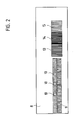
- the light beam of a light-emitting diode 20 in the projector 2 is first directed in parallel by means of a collecting optics. This light beam then illuminates a plurality of linear optical grids, which are located on a transparent graduation carrier 8. As Fig.2 shows, these grids are all oriented parallel to each other.
- a long grating 9 with zero marks 10 arranged next to it has a relatively short period length and is used in a manner known per se to measure the position of the graduation carrier 8 which is displaceable in a guide fastened to the projector 2.
- the grating 9 is assigned a photoelectric scanning system 11, the output signals of which are fed via a line 12 to an evaluation device.
- the line 12 also serves to supply power to the scanning system 11.
- the grating 9 In addition to the grating 9, three further grids 13, 14, 15 are arranged, which are projected onto the surface 1 of the object to be measured.
- the pitches of these three Ronchi gratings 13, 14, 15 consist of equally wide straight lines and gaps, the period length of the grating 13 being 1.26 mm, that of the grating 14 being 1.12 mm and that of the grating 15 being 0.28 mm.
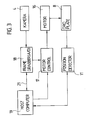
- the division carrier 8 is displaceable in a parallel guide by means of a fastening angle. The displacement takes place via a stepper motor 16, which is driven by a cable from a control stage Motor Control 17, as shown in FIG. 3. It is measured with the scanning system 11 and the grating divisions 9, 10. After passing through one of the gratings 13, 14 or 15, the light bundle of the diode 20 has a brightness distribution which varies periodically over its cross section. This light beam is widened by two optics to a cross section corresponding to object 1.
- the object surface 1 is thus illuminated with a periodic stripe pattern which can be shifted to the right or left by shifting the division carrier 8 to the side.
- the lighting phase changes periodically for all object points; phase modulation is present.
- reference signals can be generated if certain Object points go through certain lighting phases.
- This evaluation takes place according to a predetermined time sequence, which is given by the recording standard of the detector arrangement camera 4.
- the stepping motor 16 is controlled by the time sequence given by the recording standard of the camera 4 such that the strip image on the object 1 is shifted by 1/1 period length during the recording of the images.
- the detector arrangement camera 4 comprises a CCD sensor with more than 262 144 individual sensors. These individual sensors integrate the individual pixel illuminations for 20 ms each during the image shift, and then read out an overall image in each case into a memory of the frame grabber 18 evaluation electronics (see FIG. 3).
- the images output by the camera 4 are converted pixel by pixel into a digital signal format by an analog-digital converter (ADC) located in the frame grabber 18.
- ADC analog-digital converter
- the resulting 8-bit image pixel values are transferred to an add / subtract stage.
- the add / subtract stage adopts the values stored in the memories of the frame grabber 18 and returns the new values to the memories after the arithmetic operation.
- image sums (B-D) stored in one memory by image sums (A-C) stored in the other memory is carried out on the frame grabber 18 with the aid of "look-up tables" (LUT). Both image sums are first logarithmized using the LUT, and the logarithms are then subtracted from one another. By means of a further LUT, the antilogarithm and the function (arc tan) are then formed from the resulting difference.
- 262 144 values are obtained for the 262 144 pixels, from which the object point heights are calculated. Specifically, for all values from M1 log (M1) is formed, these are saved again in M1, for all values from M2 log (M2) are saved, these are saved again in M2, the difference between the stored values M1-M2 is formed and saved again in M1.
- the required residual phase values phi within the projected grating strips can in the case of a rectangular brightness distribution of the strips with an error of about 1 percent by forming the function arctan ⁇ log (-1) M1 ⁇ , otherwise be calculated using a corresponding stored value table (LUT).
- the residual phase values phi thus determined determine the heights of the individual object points within a strip of the projected pattern with respect to the lower edge of this strip.
- the absolute heights of the object points to be measured with respect to a reference plane are now determined according to the invention from the residual phase values for several period lengths of the brightness distributions on the object surface.
- the period lengths lambda effective for the height measurement are compared to the Period length lambda (0) of the projected stripe pattern increased by the factor (1 / cos (alpha)). It is now assumed that two stripe patterns with the effective period lengths lambda (1) and lambda (2) are projected so that they are in phase for a reference height of the object, that lambda (1)> lambda (2), e.g.
- n (1) p * M (2) + m (r) be calculated. This takes place in a host computer 19 (FIG. 3) which is connected to the frame grabber 18 via a line 21.
- the one described here has the following advantages:
- the determination of the absolute height of each point on the surface of the object 1 takes place without knowledge of the heights of neighboring points, the surface can therefore be discontinuous due to height jumps, and it can also consist of individual non-contiguous ones Parts exist.
- the exemplary embodiment described allows numerous variants and forms of use.
- the accuracy of the determined absolute heights z can be improved by using a brightness distribution with a period length that is significantly smaller than the period lengths of the brightness distributions from which the absolute heights z have already been determined, in order to determine the residual phase values.
- the invention can be used wherever an object surface is measured by illumination with periodic patterns, such as in interferometers, interference microscopes and in systems with pattern projection for determining technical surfaces.
Landscapes
- Engineering & Computer Science (AREA)
- Computer Vision & Pattern Recognition (AREA)
- Physics & Mathematics (AREA)
- General Physics & Mathematics (AREA)
- Length Measuring Devices By Optical Means (AREA)
Applications Claiming Priority (2)
| Application Number | Priority Date | Filing Date | Title |
|---|---|---|---|
| CH140/89A CH677972A5 (fr) | 1989-01-17 | 1989-01-17 | |
| CH140/89 | 1989-01-17 |
Publications (3)
| Publication Number | Publication Date |
|---|---|
| EP0379079A1 true EP0379079A1 (fr) | 1990-07-25 |
| EP0379079B1 EP0379079B1 (fr) | 1992-03-11 |
| EP0379079B2 EP0379079B2 (fr) | 1995-11-22 |
Family
ID=4180162
Family Applications (1)
| Application Number | Title | Priority Date | Filing Date |
|---|---|---|---|
| EP90100588A Expired - Lifetime EP0379079B2 (fr) | 1989-01-17 | 1990-01-12 | - Appareil pour l'arpentage de la surface d'un objet par projection des dessins à bandes |
Country Status (6)
| Country | Link |
|---|---|
| US (1) | US5003187A (fr) |
| EP (1) | EP0379079B2 (fr) |
| JP (1) | JPH02228511A (fr) |
| CA (1) | CA2007044A1 (fr) |
| CH (1) | CH677972A5 (fr) |
| DE (1) | DE59000059D1 (fr) |
Cited By (11)
| Publication number | Priority date | Publication date | Assignee | Title |
|---|---|---|---|---|
| WO1992001206A1 (fr) * | 1990-07-03 | 1992-01-23 | Bertin & Cie | Appareil pour la determination de la forme tridimensionnelle d'un objet par voie optique sans contact |
| DE4027328A1 (de) * | 1990-08-29 | 1992-03-05 | Siemens Ag | 3d-kamera zur erfassung von oberflaechenstrukturen, insbesondere fuer zahnmedizinische zwecke |
| FR2677753A1 (fr) * | 1991-06-15 | 1992-12-18 | Zeiss Carl Fa | Procede pour evaluer des modeles periodiques de luminosite, calculateur pour evaluer la position de phase de tels modeles et dispositif associe pour la mesure de surfaces d'objets. |
| FR2682473A1 (fr) * | 1991-10-15 | 1993-04-16 | Kaltenbach & Voigt | Procede et dispositif de relevement optique de la topographie d'objets. |
| DE4207630A1 (de) * | 1992-03-11 | 1993-09-23 | Kappa Messtechnik Gmbh | Verwendung eines stereomikroskops |
| EP0567980A1 (fr) * | 1992-04-28 | 1993-11-03 | Mtu Motoren- Und Turbinen-Union MàNchen Gmbh | Procédé pour la détermination des profils courbés d'arêtes |
| US5343294A (en) * | 1990-03-09 | 1994-08-30 | Carl-Zeiss-Stiftung | Method for analyzing periodic brightness patterns |
| DE4415834A1 (de) * | 1994-05-05 | 1995-11-09 | Breuckmann Gmbh | Vorrichtung zur optischen Vermessung von Entfernungen und räumlichen Koordinaten |
| EP0567981B1 (fr) * | 1992-04-28 | 1997-07-09 | Mtu Motoren- Und Turbinen-Union MàNchen Gmbh | Procédé pour la mensuration des profils courbés d'arêtes |
| AT404638B (de) * | 1993-01-28 | 1999-01-25 | Oesterr Forsch Seibersdorf | Verfahren und vorrichtung zur dreidimensionalen vermessung der oberfläche von gegenständen |
| US8319977B2 (en) | 2005-12-14 | 2012-11-27 | Koh Young Technology Inc. | 3D image measuring apparatus and method thereof |
Families Citing this family (22)
| Publication number | Priority date | Publication date | Assignee | Title |
|---|---|---|---|---|
| US5293687A (en) * | 1991-05-10 | 1994-03-15 | Aluminum Company Of America | Wheel manufacturing method |
| US5619587A (en) * | 1991-05-10 | 1997-04-08 | Aluminum Company Of America | System and method for contactlessly gauging the thickness of a contoured object, such as a vehicle wheel |
| US5444536A (en) * | 1992-04-28 | 1995-08-22 | Mtu Motoren- Und Turbinen-Union Muenchen Gmbh | Apparatus for measuring the curvature of a profile, such as an edge of a turbine blade |
| US5570186A (en) * | 1992-04-28 | 1996-10-29 | Mtu Motoren- Und Turbinen-Union Munich Gmbh | Method for inspecting the curvature of a profile, such an edge of a turbine blade |
| GB9216743D0 (en) * | 1992-08-07 | 1992-09-23 | Epstein Ruth | A device to calibrate adsolute size in endoscopy |
| US5430537A (en) * | 1993-09-03 | 1995-07-04 | Dynamics Research Corporation | Light beam distance encoder |
| US6690474B1 (en) * | 1996-02-12 | 2004-02-10 | Massachusetts Institute Of Technology | Apparatus and methods for surface contour measurement |
| DE19703741C2 (de) * | 1997-02-02 | 2002-02-28 | Henning Wolf | Optisches Meßverfahren zur absoluten dreidimensionalen Messung der Form von Objekten |
| US6208412B1 (en) | 1999-06-14 | 2001-03-27 | Visteon Global Technologies, Inc. | Method and apparatus for determining optical quality |
| US6100990A (en) * | 1999-06-14 | 2000-08-08 | Ford Motor Company | Method and apparatus for determining reflective optical quality using gray-scale patterns |
| DE50214827D1 (de) * | 2001-04-07 | 2011-02-10 | Zeiss Carl Microimaging Gmbh | Verfahren und Anordnung zur tiefenaufgelösten optischen Erfassung einer Probe |
| US7274446B2 (en) * | 2001-04-07 | 2007-09-25 | Carl Zeiss Jena Gmbh | Method and arrangement for the deep resolved optical recording of a sample |
| DE10118463A1 (de) * | 2001-04-07 | 2002-10-10 | Zeiss Carl Jena Gmbh | Verfahren und Anordnung zur tiefenaufgelösten optischen Erfassung einer Probe |
| US6937350B2 (en) * | 2001-06-29 | 2005-08-30 | Massachusetts Institute Of Technology | Apparatus and methods for optically monitoring thickness |
| JP4730836B2 (ja) * | 2005-09-15 | 2011-07-20 | Jfeスチール株式会社 | 面歪の測定装置及び方法 |
| US8430752B2 (en) * | 2007-06-20 | 2013-04-30 | The Nielsen Company (Us), Llc | Methods and apparatus to meter video game play |
| US8059280B2 (en) * | 2008-01-31 | 2011-11-15 | Cyberoptics Corporation | Method for three-dimensional imaging using multi-phase structured light |
| FR2936605B1 (fr) | 2008-10-01 | 2014-10-31 | Saint Gobain | Dispositif d'analyse de la surface d'un substrat |
| CA2753146A1 (fr) * | 2009-02-20 | 2010-08-26 | 3G Software & Measurement Gmbh | Systeme de projection mobile pour mise a l'echelle et orientation de surfaces controlees par un systeme de mesure optique |
| CA2771727C (fr) | 2009-11-04 | 2013-01-08 | Technologies Numetrix Inc. | Dispositif et procede d'obtention de donnees de surface d'objet tridimensionnelles |
| US20150138342A1 (en) * | 2013-11-19 | 2015-05-21 | United Technologies Corporation | System and method to determine visible damage |
| CN106123806A (zh) * | 2016-06-20 | 2016-11-16 | 四川川大智胜软件股份有限公司 | 一种基于微机电的结构光投影方案 |
Citations (4)
| Publication number | Priority date | Publication date | Assignee | Title |
|---|---|---|---|---|
| US4687325A (en) * | 1985-03-28 | 1987-08-18 | General Electric Company | Three-dimensional range camera |
| EP0262089A2 (fr) * | 1986-09-23 | 1988-03-30 | KERN & CO. AG Werke für Präzisionsmechanik Optik und Elektronik | Dispositif pour mesurer la surface d'un objet |
| EP0288983A2 (fr) * | 1987-04-29 | 1988-11-02 | Lbp Partnership | Dispositif de projection des dessins de lumière |
| GB2204397A (en) * | 1987-04-30 | 1988-11-09 | Eastman Kodak Co | Digital moire profilometry |
Family Cites Families (2)
| Publication number | Priority date | Publication date | Assignee | Title |
|---|---|---|---|---|
| US4657394A (en) * | 1984-09-14 | 1987-04-14 | New York Institute Of Technology | Apparatus and method for obtaining three dimensional surface contours |
| US4895448A (en) * | 1988-01-13 | 1990-01-23 | Laird Richard P | Method and apparatus for determining the surface quality of an object |
-
1989
- 1989-01-17 CH CH140/89A patent/CH677972A5/de not_active IP Right Cessation
-
1990
- 1990-01-03 CA CA002007044A patent/CA2007044A1/fr not_active Abandoned
- 1990-01-12 DE DE9090100588T patent/DE59000059D1/de not_active Expired - Lifetime
- 1990-01-12 EP EP90100588A patent/EP0379079B2/fr not_active Expired - Lifetime
- 1990-01-17 JP JP2006508A patent/JPH02228511A/ja active Pending
- 1990-01-17 US US07/465,788 patent/US5003187A/en not_active Expired - Fee Related
Patent Citations (4)
| Publication number | Priority date | Publication date | Assignee | Title |
|---|---|---|---|---|
| US4687325A (en) * | 1985-03-28 | 1987-08-18 | General Electric Company | Three-dimensional range camera |
| EP0262089A2 (fr) * | 1986-09-23 | 1988-03-30 | KERN & CO. AG Werke für Präzisionsmechanik Optik und Elektronik | Dispositif pour mesurer la surface d'un objet |
| EP0288983A2 (fr) * | 1987-04-29 | 1988-11-02 | Lbp Partnership | Dispositif de projection des dessins de lumière |
| GB2204397A (en) * | 1987-04-30 | 1988-11-09 | Eastman Kodak Co | Digital moire profilometry |
Cited By (15)
| Publication number | Priority date | Publication date | Assignee | Title |
|---|---|---|---|---|
| US5343294A (en) * | 1990-03-09 | 1994-08-30 | Carl-Zeiss-Stiftung | Method for analyzing periodic brightness patterns |
| US5262844A (en) * | 1990-07-03 | 1993-11-16 | Bertin & Cie | Apparatus for determining the three-dimensional shape of an object optically without contact |
| WO1992001206A1 (fr) * | 1990-07-03 | 1992-01-23 | Bertin & Cie | Appareil pour la determination de la forme tridimensionnelle d'un objet par voie optique sans contact |
| DE4027328A1 (de) * | 1990-08-29 | 1992-03-05 | Siemens Ag | 3d-kamera zur erfassung von oberflaechenstrukturen, insbesondere fuer zahnmedizinische zwecke |
| DE4027328B4 (de) * | 1990-08-29 | 2004-07-22 | Sirona Dental Systems Gmbh | 3D-Kamera zur Erfassung von Oberflächenstrukturen, insbesondere für zahnmedizinische Zwecke |
| FR2677753A1 (fr) * | 1991-06-15 | 1992-12-18 | Zeiss Carl Fa | Procede pour evaluer des modeles periodiques de luminosite, calculateur pour evaluer la position de phase de tels modeles et dispositif associe pour la mesure de surfaces d'objets. |
| FR2682473A1 (fr) * | 1991-10-15 | 1993-04-16 | Kaltenbach & Voigt | Procede et dispositif de relevement optique de la topographie d'objets. |
| DE4207630A1 (de) * | 1992-03-11 | 1993-09-23 | Kappa Messtechnik Gmbh | Verwendung eines stereomikroskops |
| EP0567980A1 (fr) * | 1992-04-28 | 1993-11-03 | Mtu Motoren- Und Turbinen-Union MàNchen Gmbh | Procédé pour la détermination des profils courbés d'arêtes |
| EP0567981B1 (fr) * | 1992-04-28 | 1997-07-09 | Mtu Motoren- Und Turbinen-Union MàNchen Gmbh | Procédé pour la mensuration des profils courbés d'arêtes |
| AT404638B (de) * | 1993-01-28 | 1999-01-25 | Oesterr Forsch Seibersdorf | Verfahren und vorrichtung zur dreidimensionalen vermessung der oberfläche von gegenständen |
| DE4415834A1 (de) * | 1994-05-05 | 1995-11-09 | Breuckmann Gmbh | Vorrichtung zur optischen Vermessung von Entfernungen und räumlichen Koordinaten |
| DE4415834C2 (de) * | 1994-05-05 | 2000-12-21 | Breuckmann Gmbh | Vorrichtung zur Vermessung von Entfernungen und räumlichen Koordinaten |
| US8319977B2 (en) | 2005-12-14 | 2012-11-27 | Koh Young Technology Inc. | 3D image measuring apparatus and method thereof |
| DE102006059132B4 (de) * | 2005-12-14 | 2012-12-06 | Koh Young Technology Inc. | Dreidimensionales Bildmessverfahren |
Also Published As
| Publication number | Publication date |
|---|---|
| US5003187A (en) | 1991-03-26 |
| EP0379079B1 (fr) | 1992-03-11 |
| CH677972A5 (fr) | 1991-07-15 |
| CA2007044A1 (fr) | 1990-07-17 |
| DE59000059D1 (de) | 1992-04-16 |
| EP0379079B2 (fr) | 1995-11-22 |
| JPH02228511A (ja) | 1990-09-11 |
Similar Documents
| Publication | Publication Date | Title |
|---|---|---|
| EP0379079B1 (fr) | - Appareil pour l'arpentage de la surface d'un objet par projection des dessins à bandes | |
| EP0451474B1 (fr) | Procédé et dispositif pour mesurer sans contact le contour superficiel d'un objet | |
| DE3122712A1 (de) | "verfahren und vorrichtung zum beruehrungslosen messen von oberflaechenprofilen" | |
| DE69705037T2 (de) | Verfahren und vorrichtung zum messen der form eines objekts | |
| AT395914B (de) | Photoelektrische positionsmesseinrichtung | |
| DE102008040949B4 (de) | Optisches Projektionsgitter, Messkamera mit optischem Projektionsgitter und Verfahren zur Erzeugung eines optischen Projektionsgitters | |
| EP0291729B1 (fr) | Procédé et dispositif pour mesurer la position des fils de trame ou des rangées de mailles dans les bandes textiles | |
| DE3306709C2 (fr) | ||
| DE4226683B4 (de) | Optischer Bewegungsaufnehmer | |
| DE102013013791B4 (de) | Verfahren und Vorrichtung zum berührungslosen Vermessen von Oberflächenkonturen | |
| DE3907430C1 (fr) | ||
| DE4007500A1 (de) | Verfahren und vorrichtung zur beruehrungslosen vermessung von objektoberflaechen | |
| EP0085951B1 (fr) | Procédé et dispositif pour établissement des grandeurs à mesurer | |
| EP0076866A1 (fr) | Procédé interpolant de la coupe optique | |
| DE112011103006T5 (de) | Verfahren und Vorrichtung zum Messen der Form eines Objekts | |
| DE3813692A1 (de) | Verfahren und vorrichtung zur digitalen moireprofilometrie, geeicht fuer die genaue umwandlung von phaseninformation in abstandsmessungen in einer vielzahl von richtungen | |
| DE19623172C1 (de) | Verfahren zur dreidimensionalen optischen Vermessung von Objektoberflächen | |
| DE2637361A1 (de) | Vorrichtung zum messen der bewegung eines ersten teiles relativ zu einem zweiten teil | |
| WO2010094658A1 (fr) | Contrôle de miroirs pivotants | |
| EP0262089A2 (fr) | Dispositif pour mesurer la surface d'un objet | |
| DE2511350C2 (fr) | ||
| EP2799810A1 (fr) | Dispositif et procédé de mesure tridimensionnelle simultanée de surfaces avec plusieurs longueurs d'onde | |
| DE2636211B1 (de) | Interferometrisches verfahren zur abstands- oder ebenheitsmessung | |
| AT404638B (de) | Verfahren und vorrichtung zur dreidimensionalen vermessung der oberfläche von gegenständen | |
| DE4009737C2 (fr) |
Legal Events
| Date | Code | Title | Description |
|---|---|---|---|
| PUAI | Public reference made under article 153(3) epc to a published international application that has entered the european phase |
Free format text: ORIGINAL CODE: 0009012 |
|
| AK | Designated contracting states |
Kind code of ref document: A1 Designated state(s): DE FR GB IT SE |
|
| 17P | Request for examination filed |
Effective date: 19900907 |
|
| RAP1 | Party data changed (applicant data changed or rights of an application transferred) |
Owner name: LEICA AARAU AG |
|
| 17Q | First examination report despatched |
Effective date: 19910723 |
|
| GRAA | (expected) grant |
Free format text: ORIGINAL CODE: 0009210 |
|
| AK | Designated contracting states |
Kind code of ref document: B1 Designated state(s): DE FR GB IT SE |
|
| PG25 | Lapsed in a contracting state [announced via postgrant information from national office to epo] |
Ref country code: GB Effective date: 19920311 Ref country code: FR Effective date: 19920311 |
|
| ITF | It: translation for a ep patent filed | ||
| GBT | Gb: translation of ep patent filed (gb section 77(6)(a)/1977) | ||
| REF | Corresponds to: |
Ref document number: 59000059 Country of ref document: DE Date of ref document: 19920416 |
|
| ET | Fr: translation filed | ||
| PLBI | Opposition filed |
Free format text: ORIGINAL CODE: 0009260 |
|
| 26 | Opposition filed |
Opponent name: FIRMA CARL ZEISS Effective date: 19921210 |
|
| RAP2 | Party data changed (patent owner data changed or rights of a patent transferred) |
Owner name: LEICA AG |
|
| PGFP | Annual fee paid to national office [announced via postgrant information from national office to epo] |
Ref country code: GB Payment date: 19941215 Year of fee payment: 6 |
|
| PGFP | Annual fee paid to national office [announced via postgrant information from national office to epo] |
Ref country code: SE Payment date: 19941219 Year of fee payment: 6 |
|
| PGFP | Annual fee paid to national office [announced via postgrant information from national office to epo] |
Ref country code: FR Payment date: 19941220 Year of fee payment: 6 |
|
| PG25 | Lapsed in a contracting state [announced via postgrant information from national office to epo] |
Ref country code: SE Free format text: LAPSE BECAUSE OF NON-PAYMENT OF DUE FEES Effective date: 19950113 |
|
| EAL | Se: european patent in force in sweden |
Ref document number: 90100588.4 |
|
| RTI2 | Title (correction) |
Free format text: - APPARATUS FOR SURVEYING THE SURFACE OF AN OBJECT BY PROJECTION OF FRINGE PATTERNS. |
|
| PUAH | Patent maintained in amended form |
Free format text: ORIGINAL CODE: 0009272 |
|
| STAA | Information on the status of an ep patent application or granted ep patent |
Free format text: STATUS: PATENT MAINTAINED AS AMENDED |
|
| 27A | Patent maintained in amended form |
Effective date: 19951122 |
|
| AK | Designated contracting states |
Kind code of ref document: B2 Designated state(s): DE FR GB IT SE |
|
| EN | Fr: translation not filed | ||
| GBV | Gb: ep patent (uk) treated as always having been void in accordance with gb section 77(7)/1977 [no translation filed] |
Effective date: 19920311 |
|
| PG25 | Lapsed in a contracting state [announced via postgrant information from national office to epo] |
Ref country code: IT Free format text: LAPSE BECAUSE OF NON-PAYMENT OF DUE FEES;WARNING: LAPSES OF ITALIAN PATENTS WITH EFFECTIVE DATE BEFORE 2007 MAY HAVE OCCURRED AT ANY TIME BEFORE 2007. THE CORRECT EFFECTIVE DATE MAY BE DIFFERENT FROM THE ONE RECORDED. Effective date: 20050112 |
|
| PGFP | Annual fee paid to national office [announced via postgrant information from national office to epo] |
Ref country code: DE Payment date: 20070110 Year of fee payment: 18 |
|
| PG25 | Lapsed in a contracting state [announced via postgrant information from national office to epo] |
Ref country code: DE Free format text: LAPSE BECAUSE OF NON-PAYMENT OF DUE FEES Effective date: 20080801 |